AER MM 200 User manual

1
MM 200
user manual
Monte Montgomery Signature Amp
Register your
MM 200:
www.aer-amps.com
> product registration

2
MM 200
user manual
Contents Page
1. Introduction 2
1.1 Monte’s needs 3
2. Important safety instructions 4
3. Controls and connections 5
3.1 Front side 5
3.2 Rear side 6
4. Starting up 7
4.1 Cabling and switching-on 7
4.2 Level adjustment 7
5. Functional Characteristics 8
5.1 Equalization 8
5.2 Eects 8
5.3 Footswitch 8
5.4 Mute 8
5.5 Phantom power 9
5.5.1 9V-Phantom power 9
5.5.2 48V-Phantom power 9
6. Technical Specications 10
7. Circuit Diagram 11
1. Introduction
Welcome to B!
Thank you for choosing the MM 200, the AER Monte Montgomery Signature amp.
A pleasure and a challange to team up with Monte and meet his requirements for power
and dynamics - he just needs it all: percussivness, edge, speed, bite but at the same
time a tone full, distinct and clear - this hard-core troubadour with his wild-mild, melodic
power-rock needs seriuos gear ... serious!
All AER-systems are subtly dynamically controlled, which ensures absolute reliability in full
load operation despite strikingly small sizes and little weight.
Read on carefully and have fun using your MM 200!

3
• Needs:
• Monte‘s playing is more than powerful, loud and dyna-
mic he is making use of a lot of eect pedals - a rather
electric/acoustic than acoustic/electric sound – Monte’s
sound!
• The volume, as such, the percussiveness and the
almost physical attack of the instrument within his style
needs a relaxed amp, with lot’s of headroom, eective
but “understated”dynamic control and a sound repro-
duction that that blends the directness and attack with a
mild and melodic character.
• A live amp, made for the stage (sic!) that works for Mon-
te as a Soloist, as well as with the Band, that supports him
with punch and intelligibility.
• Easy to operate, with the sound right there - without
tweaking and bending – and all the time. Ruggedness
and reliability match perfectly to Monte’s needs.
• Besides that a valuable additional source for recording
especially due to superb preamps and audio-circuits
along the signal pass. Line and DI-out deliver the sound
at full.
• Last, but not least, the Mute-Switch, the“Monte Mute”,
a feature indispensable for Monte’s needs. Push a button
and the amp is completely quiet!
• Thus:
• First, the speaker: we decided for enough and appropri-
ate speakers with equivalent sensitivity and fast respose.
The AER dual-cone 8”, (200mm) is perfect for that! Two
of them, diagonal, upright on the baffle board bundle
the power. They oer a power handling of 200 Watts at
93dB @1W/1m each and qualify by a strong dened
mid-range and a tight low end well capable of live sound
pressure levels.
• Second, the engine: driven by AER’s UNIV-250 Class A/B
Power amp-module used in 2 x 100 W mode to drive
each speaker separately. Specially designed to handle
high impulses the amp handles multiples of his stated
power over the rst decisive milliseconds to allow the
signal, the impulse, to pass without distortion.
• Third, features: the classic AER „singer-song-writer“ -
setup with two separate channels (instrument and voice),
separate gains and very musical eq’s, 4 eects, eect pan,
aux in, eects loop, line and DI …
• Fourth, a power package, still pretty small and
handy in classic AER look.
MM200
Monte Montgomery
Signature Amp
www.aer-amps.com | www.montemontgomery.net

4
2. Important Safety Instructions
The following guidelines shall help minimize the risk of injury through re or electric shock.
1. Carefully read these safety notes before you use
the device!
2. Keep these safety notes in a safe place.
3. Pay attention to all warnings, instructions and ad-
ditional texts on the unit.
4. This device was only designed for operation under
normal climatic conditions (temperate climate).
5. Do not install or use your amp in close proximity
to water or if you are wet yourself.
6. Do not subject your device to sudden and severe
temperature changes. This could cause moisture
condensation inside the unit, which could damage
it. In the event of moisture condensation allow the
device to dry out completely before use.
7. Use your amp in a safe place where nobody can
step on cables or trip over and damage them.
8. Pay attention to an unhindered air circulation
around the amp, never obstruct the air vents or grilles.
9. Always pull the mains plug before cleaning your
amp or when left unused for a long period of time.
Use only a dry cloth for cleaning. Avoid the use of de-
tergents and do not let any liquids seep into the unit.
10. Use only the right fuses with the same current
rating and trigger characteristic as replacements.
Never mend fuses! Pull the mains plug before repla-
cing a fuse. Should a fuse blow again after a short
while, the device needs to be checked.
11. Never install your amp close to devices with
strong electromagnetic elds such as large mains
transformers, revolving machines, neon illumination
etc. Do not lay signal cables parallel to power current
cables.
12. There are no user-serviceable components in-
side the unit. To avoid the risk of an electric shock,
the unit must not be opened. All maintenance, ad-
justment and repair works should be carried out by
qualied sta only. Any unauthorized tampering will
void the 2-year warranty.
13. In keeping with the EMV regulations screened
cables with correctly tted connectors must be used
for all signal connections.
14. Always use an earthed power supply with the
correct mains voltage. If you are in doubt about the
power outlet ground, have it checked by a qualied
technician.
15. Cable up your amp only when it is powered o.
16. This device should be installed near the socket
outlet and disconnection of the device should
be easily accessible. The mains plug of the power
supply shall remain readily operable. Protect the po-
wer cord from being walked on or pinched particu-
larly at plugs, convenience receptacles and the point
where they exit from the apparatus.
17. This product may cause permanent hearing loss.
Do not operate for long periods of time at a high
volume level or at any level that is uncomfortable.
If you experience any hearing loss or ringing in the
ears, you should consult an audiologist.
18. The product should be located away from heat
sources such as radiators, heat registers or other pro-
ducts that produce heat.
19. Do not place any open sources of re, like can-
dles, on the device.
20. Care should be taken so that objects do not fall
onto the device and liquids are not spilled into the
enclosure through openings. Ensure that no objects
lled with liquids, such as vases, are placed on the
device.
21. Do not place this device on an unstable
cart, stand, tripod, bracket or table. The de-
vice may fall, causing serious injury to you
and serious damage to the device itself.
CAUTION
RISK OF ELECTRIC SHOCK
DO NOT OPEN
ATTENTION
RISQUE DE CHOC ELECTRIQUE
NE PAS OUVRIR
The lightning ash with
the arrow head symbol
within an equilateral
triangle is intended to alert the
user to the presence of unisolated
´dangerous voltage´ within this
product´s enclosure that may
be of sucient magnitude to
constitute a risk of electric shock
to persons.
The exclamation point
within an equilateral
triangle is intended to
alert the user to the presence
of important operating and
maintenance (servicing)
instructions in the literature
accompanying this product.
5
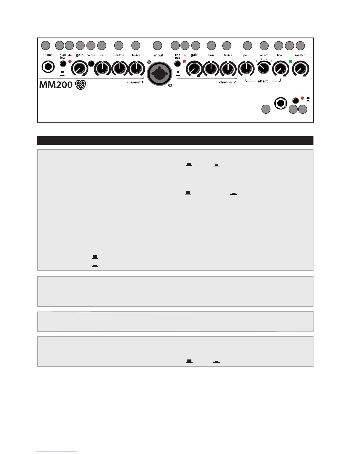
channels 1 + 2
efx
mains & master
3.1 Front side
1) input (ch. 1) signal input, socket for 6,3 mm mono jackplug
2) high/low input sensitivity switch, attenuator = o = on
3) clip overload indicator
4) gain input level control
5) colour tone colour lter activation switch = not active = active
6) bass bass frequency level control
7) middle middle frequency level control
8) treble treble frequency level control
9) input (ch. 2) signal input, combo-socket for 6,3 mm mono jackplug and
XLR-male-connectors
10) line/mic signal source selector switch (combo-socket):
line (only via jackplug) for instruments (pickup) and other line level sources
mic (only via XLR-connector) for microphones
11) pan eect signal distribution control
12) select eect select switch
13) level level control internal eect
14) power-led on/o status indicator
15) master master level control
3. Controls and Connections
Monte-Mute
Foot-Switch
31 4 46 67 8 8
9
25 10 3 11 12 13 14 15
16 1817
16) footswitch mute footswitch input socket 6,3mm, mono, on-o
17) mute on-o switch
18) mute on-o indicator = o = on mute
6
footswitchgnd
lift
9 V
tip = int. e.
ring = ext. e.
phantom
power
level aux in
L
R
tuner line out
The Acoustic People
level DI-out send return headphones
L
R
13
3.2 Rear side
1) gnd lift: Signal ground/protective ground dis-
connecting switch to prevent hum caused by
ground-loops: o = not pressed.
2) 9 V phantom power: On/o-switch for 9 Volt
phantom power (channel 1, o = not pressed, see
para. 5.4.1 on page 9).
3) level: Aux signal level control
4) aux in L/R: Stereo input for additional signal
sources, e.g. CD-player, Cinch/RCA-sockets (white =
left channel, red = right channel).
5) footswitch: Stereo connection socket for a doub-
le-footswitch (on-/o-switch, tip = internal eect/
ring = external eect on/o).
6) tuner: The tuner output supplies a pre-master sig-
nal (mono jack socket, -10 dbV) to connect an external
tuner to the MM 200.
7) line out: The line out supplies a pre-amp signal
taken after tone-control, eects and master for for-
warding to other appliances.
8) level: DI-signal level control
9) DI-out: Preamp-output (XLR male socket) with
symmetrical signal, after tone-control, pre master,
without eects.
10) send: Send is an output (mono jack socket) to
connect the MM 200 to an external eect device
and in conjunction with return (input) forms a loop
here designed as external eect loop. The eect can
be switched on or o via footswitch.
11) return: Return (mono jack socket) as part of the
eect loop operates as signal input from an external
eect device (from output of the eect device). The
eect can be switched on or o via footswitch. Re-
turn on its own can also be used as quasi auxiliary
signal input (-10 dbV).
12) headphones: This output enables you to con-
nect stereo headphones and mutes the loudspea-
ker. !!!
Warning: Only use
headphones with stereo
jackplugs in this output so-
cket!!
13) power on: Combined mains switch with mains
socket and fuse holder to switch the MM 200 on or
o.
footswitchgnd
lift
9 V
tip = int. e.
ring = ext. e.
phantom
power
level aux in
L
R
tuner line out
The Acoustic People
level DI-out send return headphones
L
R
1
3 85 6 7 9
10 11 12
2 4

7
4. Starting up
4.1 Cabling and switching on
Before connecting to mains, please ensure that your
local mains voltage is suitable for the voltage of the
device (e.g. 120V in
the USA, 230V in Euro-
pe). The relevant specs
and safety symbols are
printed on the rear side
of the unit.
4.2 Level adjustment
First ensure, that the master level control is zeroed
(over to far left), so that when you are setting the
sound level, the signal passes through the elect-
ronics only and does not reach the loudspeaker.
By pressing the high-/low- (attn.) resp. line-/mic-
switches you can adapt the amplier to your signal
sources (guitar pickups, microphone etc).
Turn the gain control clockwise until the red clip
indicator ashes momentarily when playing with a
strong attack. Thus you make sure that your signal
source (e.g. instrument) provides the input-stage of
the amplier with the necessary input.
The clip-LED indicates an overload. A short icker
is of no danger to AER devices. During operation a
short icker can be accepted, to be on the safe side
you should reduce the gain slightly to achieve an
optimal and distortion-free performance.
Finally set the desired overall volume level with the
master level control.
Note: Level adjustment
By setting the level correctly we mean the signal le-
vel in one or several devices in a signal chain is nei-
ther too high nor too low. This applies equally to all
circuits in a complete circuit design (EQs, preamps
etc.)
Consequently, care must be taken that no part of the
circuit is overloaded or that distortion is unintentio-
nally added to the signal.
We have carefully designed the circuit to achieve this
objective whilst also providing controls for„manual“
intervention.
Master-, gain- and level-control should be zero-
ed (over to far left), all other control should be in
center position, the switches should be o = not
pressed.
Connect all cables according to your application
and switch the amplier on. The green power con-
trol LED indicates operational readiness.
channel 1 channel 2
8
5. Functional Characteristics
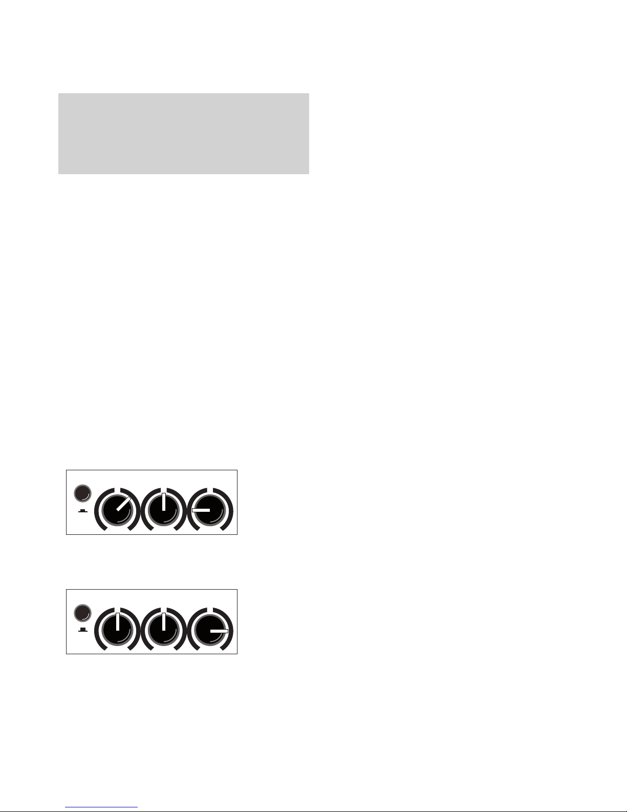
5.1 Equalization
The triple-/dual-band equalizer of your MM 200
provides you with an active and high quality sound
interaction tool that supports the natural tone of in-
struments and voice whilst simultaneously oering
you the possibility of a controlled accentuation.
With all controls in mid position the lters are set
to produce a very pleasing and natural sound im-
pression that you can „colour up“ by using the co-
lour lter with the eect of lowering the mids and
lifting the trebles. The tone becomes more open
and light and is especially suited for ngerpicking
techniques.
The equalization can support or soften the eect of
the colour lter and allows a dierentiated mids-
accentuation (see g. below).
5.3 Footswitch
A standard double-footswitch (on-/o-switch)
can be plugged into the footswitch-socket on the
rear side of the amplier via stereo cable. By this
footswitch the internal and external eects can be
switched on and o.
5.2 Eects
The MM 200 has a built-in (internal) digital eect
processor, with the select-switch you can choose
between 4 dierent eects:
1 = reverb 1 (short)
2 = reverb 2 (long)
3 = delay (320 ms)
4 = chorus
The efx-level-control determines the intensity of
the internal eects (left stop = no eect).
Furthermore an additional eects unit (external
eect) may be connected to the MM 200. For this
purpose use the send and return sockets on the
rear side of the amplier (send goes to input, re-
turn to the output of the external eects device).
The intensity of the eect is adjusted at the external
eects unit.
With the efx-pan control the dierent eects are
blended with the original signal. The efx-pan works
as follows:
left stop: internal eff ect on channel 1
external eect on channel 2
mid position: internal eff ects on channels 1 + 2
external eff ects on channels 1 + 2
right stop: internal eff ects on channel 2
external eects on channel 1
colour bass middle treble
A: with colour- lter (switch pressed)
reduce treble to soften possible sharpness
colour bass middle treble
B: without colour- lter (switch not pressed)
boost treble to brighten the sound
Note: The active equalization of the MM 200 eects
the signal adjustment. If you spot an intensied i-
ckering of the clip indicator, level the signal level
with the gain control (see para. 4.2 Level adjust-
ment).
5.4 Mute Function
A standard mono-footswitch (on-/o-switch) can be
connected to the mute foot-switch-socket on the
top side of the amplier. By this footswitch the amp
can be muted (headphones, tuner and eect send
are not eected). The footswitch sets the mute
push button out of function.

9
5.5 Phantom power
5.5.1 9V Phantom power
Channel 1 of the MM 200 is equipped with 9V
phantom power as current supply for external de-
vices, e.g. active guitar electronics. A stereo-jack-
cable is required for this purpose, phantom power
is switched on by the 9V-switch on the rear side of
the MM 200 and is connected to the ring-contact
of the jack plug. Signal sources which don’t requi-
re phantom power may as usual be connected via
mono jack cable, please ensure that phantom pow-
er is switched o in that case.
Note: Wrong use of phantom power may damage
your pickup or additional equipment. To avoid harm,
please regard the following hints:
eOnly units which are explicitly designed for this
operation purpose should be provided with 9V
phantom power. In all other cases (as well if you are
in doubt) keep the switch o = not pressed.
eTo be on the safe side always use mono jack cable,
when no phantom power is needed.
eMake sure that cables are plugged-in completely,
avoid leaving the plug halfway pulled out.
5.5.2 48V Phantom power
The XLR-socket of channel 2 is equipped with 48V-
phantom power for microphones that require this
(e.g. condenser microphones).
General Note: Use of 48V or 24V phantom power
(Phantom power = remote supply, here: powering
an audio device via the connected audio line)
Turn on the phantom power only if the unit connec-
ted to an XLR socket is designed to handle it!
In general, suitable units are e.g. condenser micro-
phones, active DI-boxes and other special audio
devices, whose power supply is drawn from the
phantom power. Such devices are also labelled ac-
cordingly; please heed the permissible power con-
sumption (max.10mA).
High-quality dynamic microphones with a balanced
signal need no phantom power, but can handle it
anyway.
Other devices, which have not been designed expli-
citly for phantom power operation, can suer from
considerable malfunctions and damage may result
as well.
Examples of devices that may be damaged by in-
correct application of phantom power include:
Low-cost dynamic microphones with a mono jack-
plug (unbalanced signal) that were tted afterwards
with an XLR connector.
Audio devices with a balanced XLR output (e.g. DI-
boxes, eects devices, instrument preamps with
a DI output etc.) which are not protected against
phantom power applied to their XLR output. (The
DI connectors on AER products are protected
against applied phantom power.)
Other audio devices (such as preamps, eects pe-
dals etc.) whose unbalanced line output was repla-
ced by an XLR socket.
If in doubt please consult the manufacturer of the
device you are using.
P.S. For further questions or suggestions contact us:
10
Inputs (note 1)
Channel 1 Jack 1⁄4” (6.35 mm), unbalanced input
Sensitivity: 38 mV (-28 dBV)
Impedance: 2.2 Megohm
Noise (note 3): 1.8 µV (-115 dBV),
A-weighted
Phantom power:
9 V at‘ring’ terminal (max. 100 mA).
Switchable.
High/low switch: 10 dB attenuator
Channel 2 Jack 1⁄4” (6.35 mm) + XLR combo socket
Line mode:
Unbalanced mono jack input only
Sensitivity: 64 mV (-24 dBV)
Impedance: 1 Megohm
Noise (note 3): 2.8 µV (-111 dBV),
A-weighted
Mic mode:
XLR (balanced), stereo jack (balanced), or
mono jack (unbalanced) input
Sensitivity: 5.4 mV (-45 dBV)
Impedance: 1.2 k (balanced use),
or 4.2 k (unbalanced use)
Noise (note 3): 2.2 µV (-113 dBV),
A-weighted
Phantom power: 48 V (XLR only)
Voice lter: -10 dB at 270 Hz (referred to 10 kHz)
Clip indic. Threshold: 8 dB below actual clipping
(Ch. 1 and 2)
Aux in Stereo cinch (RCA), L + R mixed and added
pre-master.Sensitivity: 2 x 44 mV (-27 dBV),
adjustable Impedance: 22 k
Return Eect return for parallel eect loop. Eect
signal is added pre-master.
Mono jack, unbalanced
Relative gain of send-return loop: +2 dB
Sensitivity (note 1): 760 mV
Impedance: 20 k
Outputs (note 2)
Tuner Mono jack, unbalanced, 310 mV (-10 dBV),
post equalizer, pre eects, pre master
Line out Mono jack, unbalanced, 1.5 V (+3 dBV),
post master
DI out XLR, balanced, adjustable 0–130 mV (-18 dBV),
post equalizer, pre eects, pre master
Send Mono jack, unbalanced, 1.25 V (+2 dBV)
if “pan” control is set fully clockwise, post
eqalizer, pre eects, pre master
Headphones Stereo jack
Output power: max. 100 mW / 32 ohms
Input sensitivity: 30 mV at channel 1 input for
2 x 50 mW / 32 ohms
Internal speaker is muted while headphones
are connected.
For stereo headphones only. You should not
connect anything with a mono jack plug!
Footswitch Stereo jack,
tip = internal eect on/o,
ring = external eect on/o,
sleeve = ground.
Mute
Footswitch Mono jack, on/o,
Switch on/o, no function if Mono jack is connected
Equalizer
Channel 1 Colour: -3 dB at 700 Hz,
and +10 dB at 8 kHz
Bass: ±8 dB at 100 Hz (shelf type)
Middle: ±6 dB at 800 Hz
Treble: ±8 dB at 10 kHz (shelf type)
Channel 2 Bass: ±8 dB at 100 Hz (shelf type)
Treble: ±11 dB at 10 kHz (shelf type)
Eects
Built-in eects 1 reverb 1 (short)
2 reverb 2 (long)
3 delay (320 ms)
4 chorus
Power
Power amp 2 x 100 Watt / 4 ohms, (THD < 1%),
discrete bipolar transistor design. Dynamic
range: 100 dB (A-weighted, see note 3
Limiter threshold RMS limiter 85 W
Analog signal Subsonic lter, low distortion RMS limiter
processing
Speaker 2-way system, 8” (200 mm) full-range,
extended mode
Mains power AC 100, 120, 230, or 240 V models,
50–60 Hz, max. 450 W
Mains fuse 5 x 20 mm
slow 3.15 A for 230 and 240 V models
slow 6.3 A for 100 and 120 V models
General
Cabinet 15 mm (0.6”) birch plywood
Finish waterbased acrylic, black spatter nish
Dimensions Height: 420 mm (16.5”)
Width: 360 mm (14.2”)
Depth: 300 mm (11.8”)
Weight 15kg (33.1 lbs)
Notes:
1. Input sensitivities refer to 2 x 85 watts into 4 ohms at full gain and
volume settings, neutral tone control settings and 1 kHz sine-wave
test signal.
2. Output levels refer to 50 mV / 1 kHz input at channel one, unless
stated otherwise.
3. Equivalent input noise voltage obtained by measuring noise
voltage at the speaker and dividing by the eective voltage gain of
the amplier for the respective input. Full gain and volume settings,
neutral tone control settings, input shorted, frequency range
20 Hz – 20 kHz. Dynamic range: Range between output signal at
limiter-threshold and A-weighted output noise with master volume
in zero position.
4. Options: Gain of channel 2 in mic mode can be decresed by 4.6
dB by internal jumper. 48V phantom power can be deactivated by
internal jumper.
0 dBV = 1 V
Specications and appearance subject to change
without notice.
TD140701
6. Technical Data MM 200

11
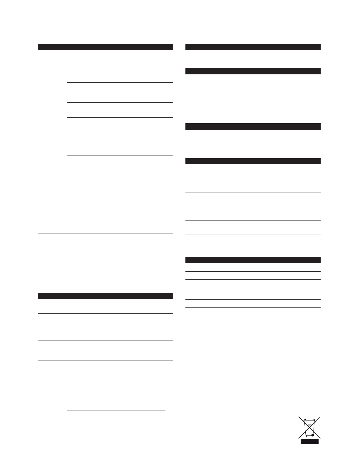
B090218B_MM200_20140701
LINE
MIC
MIC
LINE
CH1 PREAMP
+9V
HIGH / LOW
GAIN COLOUR MIDDLE
COLOUR
SUBSONIC LIMITER DUAL POWER AMP
DIGITAL EFFECTS
DUAL CONE SPEAKER
TUNER
TREBLEBASS
BASS TREBLE
SEND
EFX / LEVEL
MASTER
LINE OUT
FOOTSWITCH
RETURN
DI-out
EXT. EFFECTINT. EFFECT
GAIN
+48V
PREAMP VOICE
6k8
6k8
CH2
EFX / PAN
PREAMP
MIC GAIN H/L
EFX / SELECT
L
R
AUX LEVEL
CLIP DETECTION
CLIP DETECTION
CLIP DETECTION
CLIP DETECTION
9V Phantom Power
HEADPHONES
HEADPHONES AMP
DUAL CONE SPEAKER
DI OUT LEVEL
MUTE
MUTE
FOOTSWITCH
MUTE
MUTE
MUTE
MUTE
EFFECT
AUX IN
CW CW
TR
T R
1
2
3
1
2
3
TR
SRT
T S
7. Circuit Diagram MM 200

12
12
www.aer-amps.com
MM 200 - 2014_07_GB
Follow us on Twitter: twitter.com/aer_amps
Other manuals for MM 200
1
Table of contents
Other AER Amplifier manuals


AER
AER The Acoustic People Compact 604 User manual

AER
AER Compact mobile User manual

AER
AER amp one User manual

AER
AER Compact Classic pro User manual

AER
AER Domino 2A User manual

AER
AER Domino 2A User manual

AER
AER Compact 60 3 User manual

AER
AER COMPACT 60 2 User manual

AER
AER BINGO User manual

AER
AER Basscube User manual


Popular Amplifier manuals by other brands


Linear Power
Linear Power 302IQ Owner's manual and installation guide

Behringer
Behringer EUROCOM SN2408 quick start guide

Renishaw
Renishaw apply innovation SPA2 installation guide

THÖRESS
THÖRESS EHT Integrated Amplifier MKII instruction manual

MTX
MTX Thunder 251D owner's manual

Inter-m
Inter-m MA-106A Operation manual