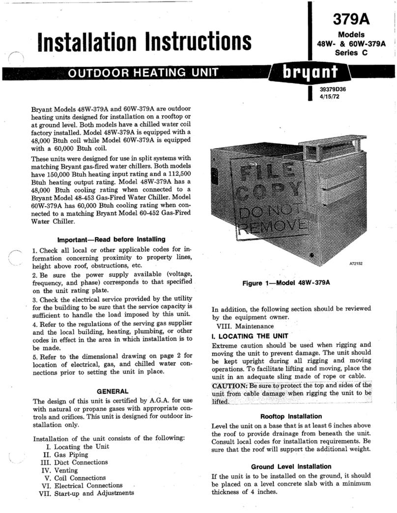
AERA ERP PRO Series User manual

VESTA HR
ÇAPRAZ AKIŞLI IGK
User’s
Manual ERP PRO
Cross Flow
Heat Recovery Unit

2
Safety .............................................. 3
Control List ...................................... 4
ERP PRO ......................................... 5
Technical Specifications.................... 7
Dimensions ...................................... 7
Performance Curves......................... 8
EcoDesign Points ............................. 9
Components .................................... 9
Installation...................................... 10
Transportation & Storage ................ 13
Electrical Connections .................... 14
Wiring Diagrams ............................. 15
Controls......................................... 24
Maintenance .................................. 28
Troubleshooting.............................. 32
Warranty ........................................ 34
Spare Part List ............................... 36
After Sales Service ......................... 37
CONTENTS

AERA AIR INNOVATION 3
Safety
This product must not be disassembled under any circumstances. Only authorized repair
technicans are qualified to conduct disassembly and repairs.
Failure to heed this warning may result in fire, electrical shock or injury.
Do not install this product in a refrigerated warehouse, heated swimming pool or other
location where temperature and humidity are significantly different. (Failure to heed this
warning may result in electrical shock or malfunctioning.)
Do not install this product where it will be directly exposed to rain. (Failure to heed this
warning may result in electrical shock or malfunctioning.)
Do not install this product in a location where acid, alkali or organic solvent vapors, paints or
other toxic gases, gases containing corrosive components or high concentrations of oily
smoke are present. (Failure to heed this warning may result not only in malfunctioning but also
fire, power leakage and electrical shock.)
Do not use this product outside the range of its rated voltage and control capacity. ERP
1200, ERP 2200 and ERP 3200; Single phase, 220- 240 V, 50 Hz., ERP 4200 Three phase,
380- 400 V, 50 Hz. (Failure to heed this warning may result in fire or electrical shock.)
Install this product in an environment where the temperature ranges from -10 °C to +40 °C
and the relative humidity is less than 80%. If condensation is expected to form, heat up the
fresh outside air by a duct heater etc.
Select a position for introducing the outside air where no exhaust or combustion gases will
be sucked into the fresh air duct and where it will not be covered by snow (Failure to ensure a
supply of air can result in producing a state of Oxygen deficiency inside the room.)
Select an adequately sturdy position for installing the product and install it properly and
securely. (Injury may result if the product should fall.)
Use the designated electrical wires for the terminal board connections and connect the wires
securely so that they will not be disconnected. (Failure to ensure proper connections may
result in fire.)
When passing metal ducts through wooden buildings clad with metal laths, wire laths or
metal, these ducts must be installed in such a way that they will not make electrical contact
with metal laths, wire laths or metal sheets. (Power leakage can cause ignition.)
The outside ducts must be tilted at a gradient(1/30 or more) downwards toward the outdoor
area from the main unit, and properly insulated. (The entry of rain water may cause power
leaks, fire or damage to household property.)
Gloves should be worn during installation. (Failure to heed this warning may result in injury.)
A dedicated circuit breaker must be installed at the origin of mains power supply. This circuit
breaker must be provided with a means for locking (lock and key).
Connect the product properly to the ground. (Malfunctioning or power leaks can cause
electrical shock.)
An isolator switch having a minimum contact gap of 3 mm in all poles must be provided as a
means of disconnecting the power supply.

4
Control List
1Make sure the unit receives power and grounding is done!
2Make sure the length of electric cables is correct! (Check for overheating on cables!)
3Check if the cables heading to the electrical box are shielded (protected against magnetic
field) and shield is grounded. If not, replace!
4Check if the exhaust and supply filters are clean and make sure they do not prevent air flow!
5Make sure the drain hose is connected and check for any blockages through the drain line!
If needed, clean it!
6Please check that the duct dimensions used in the duct system are correct and of the same
dimension of the units duct connection. If wrong correct it with appropriate one.
7Make sure there is enough service space for installation. If not, repeat installation.
8In extremely cold climates in which freezing may occur on the heat recovery unit, use electric
pre-heater at the fresh air suction to raise the air temperature to -8 °C or above.
9Make sure electrical connections are done as it is described in this manual. Make necessary
corrections if there is any faulty connection.
10 Check for unusual noise or vibration after the installation. If there is, control if anti-vibration
pads are used.

AERA AIR INNOVATION 5
ERP PRO
The limited availability of energy resources has increased energy costs, making
energy access difficult. States have begun to establish efficiency criteria in energy-
using devices in order to reduce the consumption of limited energy, and these
criteria have become compulsory for producers. The energy criteria in ventilation
devices are determined by the European Union with the Ecodesign directive,
which became compulsory since 2016 and it has been set as a prerequisite of CE
certification.
Heat recovery ventilation appliances, which are present in a significant part of
small, large and medium sized projects in the market, are listed in accordance with
the heat recovery utilization and expenditure fan power criteria in the direction of
the directive entered into force in 2016, and the entry of non-standard devices into
EU countries is prohibited.
Special Features of ERP PRO
1. EC Fans with low SFP value.
2. Plate heat recovery exchanger with large heat transfer surface area (μ> 73%).
3. F7 on fresh air side, M6 class filter on exhaust air.
4. ECO-DESIGN 2018 compliant performance.
5. Easy Service thanks to service friendly casing design.
6. Modern Automatic Control.
7. By-pass Ventilation.
System Description
ERP units are designed for ventilation of spaces by means of exhausting stale air
indoors and introducing fresh air from outdoors. ERP units recover part of the
energy of the exhaust stream to precondition fresh air. The energy recovered is
transferred to the fresh air and reduce the necessary load of the air conditioning
system.
Heat Exchange Mode
Return Air from the indoors passes through the heat recovery exchanger and is
ejected outdoors. Fresh outdoor air is supplied through the heat exchanger.

6
ERP PRO
Bypass Ventilation Mode
The main function of Automatic bypass is not to channel the fresh outside air
through the heat exchanger, but rather through the “bypass channel” in the unit
past the heat exchanger and directly into the supply air rooms.
Bypass closed:
Outside air is channeled through heat exchanger into the room = Active heat
recovery
Bypass opened:
Outside air is channeled through heat exchanger into the room = Active heat
recovery.
Outside air is channeled directly into the room = Inactive heat recovery, indirect
“cooling “of room air.
The bypass is normally used in the summer months for “night cooling “. With regard
to night cooling. the effect of cool outside temperatures is used in comparison to
room or inside temperatures.
The bypass can also be used in transition periods (spring and autumn) if the room
temperature is significantly higher than the outside air temperature during the day
due to high windows (“natural bypass cooling “).
The night cooling effect and “natural bypass cooling “is strongly influenced by the
temperature differences between outside air/supply air and room air, the flow rate,
the shade and the required cooling loads. Bypass cooling will never replace air
conditioning

AERA AIR INNOVATION 7
Technical Specifications
Dimensions
Model
ERP PRO
1200 2200 3200 4200
MAXIMUM AIR FLOW (m3/h) 1170 2000 3200 4200
MAXIMUM POWER CONSUMPTION (W) 1000 960 1560 3000
MAXIMUM CURRENT (A) 5,00 5,00 7,80 4,80
SUPPLY VOLTAGE 230 V / 50 Hz / 1 ~ 380 V / 50 Hz / 3 ~
FILTER CLASS (EXHAUST/FRESH AIR) M6/ F7
WEIGHT (kg) 148 195 406 420
SOUND PRESSURE (dB) 48 54 54 53
Sound values are measured for a ducted unit at 250Hz and 1,5m away from the unit.
The filter class is specified according to EN779: 2012 standard.
MODEL
DIMENSIONS
L D H L2 D2 L3 D3 AXB
mm
ERP PRO 1200 1752 1102 500 1790 1030 - - 300x300
ERP PRO 2200 1990 1232 580 2030 1150 - - 350x350
ERP PRO 3200 2500 1600 685 2415 1750 1207.5 1658 435x435
ERP PRO 4200 2500 1600 815 2415 1750 1207.5 1658 435x435
D
L2
B
A
D2
H
L
L2
D2
L3 L3
D3

8
Performance Curves
1000
900
800
700
600
500
400
300
200
100
0
0
200
400
600
800
1000
1200
1400
1600
1800
2000
1000
900
800
700
600
500
400
300
200
100
0
0
500
1000
1500
2000
2500
3000
3500
4000
4500
5000
1000
900
800
700
600
500
400
300
200
100
0
0
300
600
900
1200
1500
1800
2100
2400
2700
3000
1000
900
800
700
600
500
400
300
200
100
0
0
500
1000
1500
2000
2500
3000
3500
4000
4500
5000
ERP PRO-1200 AIR PERFORMANCE CURVE
ERP PRO-3200 AIR PERFORMANCE CURVE
ERP PRO-2200 AIR PERFORMANCE CURVE
ERP PRO-4200 AIR PERFORMANCE CURVE
Pa
Pa
Pa
Pa
m3/h
m3/h
m3/h
m3/h
Reference ECODesign Point
Max. Recommended Working Point
Reference ECODesign Point
Max. Recommended Working Point
Reference ECODesign Point
Max. Recommended Working Point
Reference ECODesign Point
Max. Recommended Working Point

AERA AIR INNOVATION 9
EcoDesign Points
Components
1Heat Exchanger
2Fan
3Filter
4By-Pass Damper
5Controls
6Casing
7Duct Connections
8Alternative Duct Connections
9Filter Service Cover
10 Fan Service Cover
11 Second Stage Filter Service Cover
12 Optional Second Stage Filter
2
3
4
6
7
8
9
10
11
12
1
EcoDesign Points
ERP PRO 1200 ERP PRO 2200 ERP PRO 3200 ERP PRO 4200
Declared typology Bidirectional Bidirectional Bidirectional Bidirectional
Type of drive Variable Variable Variable Variable
Type of HRS Recuperative Recuperative Recuperative Recuperative
Thermal efficiency of heat recovery [ % ] 73 73 73 73
Nominal NRVU flow rate [ m3/h ] 1170 2000 3200 4200
Effective electric power input [ kW ] 0,4 0,95 1,45 2,76
SFPint [ W/(m3/s) ] 574 538 685 767
Face velocity [ m/s ] 1,42 1,68 1,85 1,94
Normal external pressure [ Pa ] 100 100 100 100
Internal pressure drop of ventilation
components [ Pa ] 243 283 366 390
Static efficiency of fans [ % ] 54,7 59,9 59,4 54
Declared maximum external leakage
[ % ] <1 <1 <1 <1
Declared maximum internal leakage
[ % ] <3 <3 <3 <3
Description of visual filter warning Time controlled
Casing sound power level (Lwa) [ dB(A) ] 58 57 61 63
ErP Compliance 2018 2018 2018 2018

10
Installation
Roof bolt
(provided by the installation company)Duct
Elbow
(To prevent
rain water
from entering
into the duct system)
EA
(exhaust air
exhaust port)
SA
(Supply
air)
RA
(Return
air)
OA
(outside air
suction port)
Maintenance
cover
Fresh air
register
Exhaust air
suction register
Roof bolt
(provided by the installation company)Duct
Elbow
(To prevent
rain water
from entering
into the duct system)
EA
(exhaust air
exhaust port)
SA
(Supply
air)
RA
(Return
air)
OA
(outside air
suction port)
Maintenance
cover
Fresh air
register
Exhaust air
suction register
Mounting the Appliance
VESTA ERP series appliances can directly be mounted on a vibration-free solid
wall with the suspension parts supplied for installation purpose. The screws must
be applied in a torque enough to secure a rigid connection. The other part is
mounted to the wall and used as a hanger to fix the unit. Following aspects must
be considered during mounting of the unit.
The device must be installed at the ceiling level.
The installation space must be freezing free.
ERP PRO 1200 & 2200
ERP PRO 3200 & 4200

AERA AIR INNOVATION 11
Installation
The distribution ducts should be connected to the unit through rigid or semi flexible
ducts in order to avoid abnormal sounds and vibration. Flexible ducts may also
be used ensuring that the structure of the duct does not block the air stream and
cause vibration.
Check the strength of the stems
during assembly.
WARNING
Anti-vibration pad
(vibration absorber)
Bolt (M10 or M12)
Lock nut
Nut
Washer

12
Installation
Connecting the ducts
The duct connections in the unit are made of ABS material hence do not need
additional insulation. After connecting the unit; make sure that there is no leakage
between the duct connections of the unit and the duct. Use a duct tape where
necessary.
Fresh
Air
Diffuser
EA
(exhaust
air
exhaust
port)
OA
(outside
air
suction port)
Service area Exhaust
Air
Suction
Diffuser
Service space
Service area
Service space
Model SIDE SERVICE AREA DXL HEIGHT FROM THE BOTTOM SERVICE H
ERP PRO 1200 750mm x1850mm 600mm
ERP PRO 2200 850mm x2100mm 750mm
ERP PRO 3200 1000mm x2500mm 750mm
ERP PRO 4200 1000mm x2500mm 900mm
H

AERA AIR INNOVATION 13
Installation
Transportation & Storage
Transportation
All heat recovery devices manufactured by AERA are
passed through all tests and controls and shipped
from the factory. Appropriate lifting methods should
be used to prevent damage to the heat recovery
devices during vertical or horizontal transportation.
Transpallets or forklifts can be used to carry and lift
these devices. During lifting and transportation, the
appliance must be secured and safety measures must
be taken for safety. Lifting and carrying should be
done by trained and experienced personnel. Ensure
that the weight is uniformly distributed across the four
corners during carry of the devices.
Storage
All heat recovery devices manufactured by AERA
are located in a place after shipment If storage is
required, close all openings to avoid contamination.
The environment in which the heat recovery device is
stored should have minimum temperature of -20 ° C,
maximum temperature of + 40 ° C and maximum of
80% relative humidity. It must be stored in a closed
box away from dust and moisture to avoid damaging
the devices. Prevent the electrical components and
components from being damaged when performing
the packaging of the device. Accessories such as
filters, must be packaged separately to avoid exposure
to dust and moisture.
Before connecting the ducts, check that no sawdust or any other foreign material
(scraps of paper, vinyl, building material etc.) exist in the ducts.
Do not touch the damper clamp (plate) inside the unit when connecting to ducts
as it may cause malfunctioning of the by-pass system.
Do not install the ducts as shown on the following figures. Doing so will increase
the pressure drop, decrease the air volume from the unit and give rise to abnormal
sounds.
Steep
turn
Multiple
elbows
Elbow
after
unit
Sudden contraction
and/or
expansions
in duct diameter

14
Electrical Connections
The figure shows the terminal of ERP PRO units. Both the remote control and
the mains must be connected to the terminal shown. L, N connections must be
connected to the main electrical distribution system and A, B must be connected to
the remote controller. In the remote control there exists a mini PCB terminal named
with the same letters. In the electrical box the ground must also be connected from
the main electrical distribution system.
Ensure that the field supplied electrical components (mains power switch, circuit
breakers, wires, connectors and wire terminals) have been properly selected
according to the given data. Make sure that they comply with national and regional
electrical codes. Make sure that the cable section used among connections are
not smaller than 1,00 mm2 for standard units and 1,5 mm2 when electrical pre
heater is used as listed in EN 60335-1 European Standard
Please make sure that for Remote Control connection a shielded cable is used
and connected to the ground properly.
• In the case that power cabled are connected in series, add each units /
components maximum current and select wires according to below table.
• Follow local codes and regulations when selected field wires, circuit breakers
and earth leakage breakers.
• Use the wires which are not lighter than the ordinary polychloroprene sheathed
flexible cord.
Remote Control
Connection
Mains
Connection

AERA AIR INNOVATION 15
Wiring Diagram
COM
NC
DAMPER
220 V
FREEZE - SENSOR
RA - SENSOR
OA - SENSOR
EXHAUST
FAN
PWM 0-10V
GND
SUPPLY
FAN
PWM 0-10V
GND
OPTIONAL CO2 SENSOR
24 V
GND
OPTIONAL HUMIDITY SENSOR
CO2
HMD
ON-OF
J2
J4
J5
BS95 4A
BS95 4A
J6 BS95 3A
Molex 2x8 5557 type
J9 BS95 7A
J13 BS95 6A
CONTACTOR
SWITCH
RESISTANCE
PE
CABLE CONNECTION
TERMINALS
TEMP. SENSOR
56
DEFINITION OF ELECTRICAL SCHEMA:
ALL RIGHTS OF THIS DOCUMENT BELONG TO AERA. COPYING OR REPRODUCING IS NOT ALLOWED WITHOUT WRITTEN PERMISSION. ELECTRICAL SCHEMA NO:
DATE OF ISSUE:
REVISED NO:
ESEP001A
ERP PRO ELECTRICAL SCHEMA
2 3 4
SIGN
NAME
APPROVED:
DRAWN BY
DATE
CHECKED: FATİH UZUN
FATİH UZUN
1 2 3 4 5 6
1
15.10.2017
15.10.2017
A
B
C
D
A
B
C
D
R&D
APPROVED
REVISION NOTES
SUPPLY
FAN
RETURN
FAN
MAINS
CONNECTION
REMOTE
CONTROL
CONNECTION
6
5
4
3
2
1
L
N
GND
L
N
GND

16
Wiring Diagram
FREEZE - SENSOR
RA - SENSOR
OA - SENSOR
EXHAUST
FAN
PWM 0-10V
GND
SUPPLY
FAN
PWM 0-10V
GND
OPTIONAL CO2 SENSOR
24 V
GND
OPTIONAL HUMIDITY SENSOR
CO2
HMD
COMMON GND
PRE HEATER (FROZEN)
SAFETY THERMOSTAT
1ST STEP HEATER
2ND STEP HEATER
ON-OF
NOTE: YOU MUST CONNECT LINES AS SERIAL IF YOU WILL RUN BOTH PRE
AND AFTER HEATER
6
5
4
3
2
1
56
2 3 4
1 2 3 4 5 6
1
A
B
C
D
A
B
C
D
COM
NC
DAMPER
220 V
J2
J4
J5
BS95 4A
BS95 4A
J6 BS95 3A
Molex 2x8 5557 type
J9 BS95 7A
J13 BS95 6A
CONTACTOR
SWITCH
RESISTANCE
PE
CABLE CONNECTION
TERMINALS
TEMP. SENSOR
DEFINITION OF ELECTRICAL SCHEMA:
ALL RIGHTS OF THIS DOCUMENT BELONG TO AERA. COPYING OR REPRODUCING IS NOT ALLOWED WITHOUT WRITTEN PERMISSION.
ELECTRICAL SCHEMA NO:
R&D
APPROVED
REVISION NOTES
DATE OF ISSUE:
REVISED NO:
ESEP002A
ERP PRO ELECTRICAL SCHEMA WITH HEATER
SIGN
NAME
APPROVED:
DRAWN BY
DATE
CHECKED:
FATİH UZUN
FATİH UZUN
15.10.2017
15.10.2017
SUPPLY
FAN
RETURN
FAN
MAINS
CONNECTION
REMOTE
CONTROL
CONNECTION
6
5
4
3
2
1
L
N
GND
L
N
GND

AERA AIR INNOVATION 17
Wiring Diagram
56
2 3 4
1
1 2 3 4 5 6
A
B
GND
0
1
PRE
HEATER
80
70
60
50
LIMIT
THERMOSTAT
ELECTRICAL HEATER
L1 L2 L3
CONTACTOR 1
CONTACTOR
RESISTANCE
PE
TERMINALS
70
60
THERMOSTAT
NOTE: YOU MUST CONNECT LINES AS SERIAL IF YOU WILL RUN BOTH PRE
AND AFTER HEATER
COMMON GND
PRE HEATER (FROZEN)
SAFETY THERMOSTAT
1ST STEP HEATERI
2ND STEP HEATER
1
2
3
4
5
6
A
B
C
D
A
B
C
D
DEFINITION OF ELECTRICAL SCHEMA:
ALL RIGHTS OF THIS DOCUMENT BELONG TO AERA. COPYING OR REPRODUCING IS NOT ALLOWED WITHOUT WRITTEN PERMISSION.
ELECTRICAL SCHEMA NO:
DATE OF ISSUE:
REVISED NO:
ESEP003A
ERP PRO ELECTRICAL SCHEMA WITH PREHEATER
SIGN
NAME
APPROVED:
DRAWN BY
DATE
CHECKED:
FATİH UZUN
FATİH UZUN 15.10.2017
15.10.2017
ELECTRICAL HEATER CAN BE
MONOPHASE OR TRIPHASE ACCORDING
TO POWER OF APPARATUS.
R&D
APPROVED
REVISION NOTES

18
Wiring Diagram
56
2 3 4
1
1 2 3 4 5 6
A
B
GND
0
1
80
70
60
50
LIMIT
THERMOSTAT
ELECTRICAL HEATER
L1 L2 L3
CONTACTOR 1
ELECTRICAL HEATER CAN BE
MONOPHASE OR TRIPHASE ACCORDING
TO POWER OF APPARATUS.
1
2
3
4
5
6
STAGE
1
A
B
C
D
A
B
C
D
DEFINITION OF ELECTRICAL SCHEMA:
ALL RIGHTS OF THIS DOCUMENT BELONG TO AERA. COPYING OR REPRODUCING IS NOT ALLOWED WITHOUT WRITTEN PERMISSION.
ELECTRICAL SCHEMA NO:
DATE OF ISSUE:
REVISED NO:
ESEP004A
ERP PRO 1STAGE ELECTRICAL HEATER SCHEMA
SIGN
NAME
APPROVED:
DRAWN BY
DATE
CHECKED:
FATİH UZUN
FATİH UZUN
15.10.2017
15.10.2017
CONTACTOR
RESISTANCE
PE
TERMINALS
70
60
THERMOSTAT
NOTE: YOU MUST CONNECT LINES AS SERIAL IF YOU WILL RUN BOTH PRE
AND AFTER HEATER
COMMON GND
PRE HEATER (FROZEN)
1ST STEP HEATER
2ND STEP HEATER
SAFETY THERMOSTAT
R&D
APPROVED
REVISION NOTES

AERA AIR INNOVATION 19
Wiring Diagram
56
2 3 4
1
1 2 3 4 5 6
A
B
A
B
GND
0
1
L1 L2 L3
STAGE
2
STAGE
1
80
70
60
50
LIMIT
THERMOSTAT
ELECTRICAL HEATER
L1 L2 L3
CONTACTOR 3
CONTACTOR 2
1
2
3
4
5
6
A
B
C
D
A
B
C
D
DEFINITION OF ELECTRICAL SCHEMA:
ALL RIGHTS OF THIS DOCUMENT BELONG TO AERA. COPYING OR REPRODUCING IS NOT ALLOWED WITHOUT WRITTEN PERMISSION.
ELECTRICAL SCHEMA NO:
DATE OF ISSUE:
REVISED NO:
ESEP005A
ERP PRO 2 STAGE ELECTRICAL HEATER SCHEMA
SIGN
NAME
APPROVED:
DRAWN BY
DATE
CHECKED:
FATİH UZUN
FATİH UZUN
15.10.2017
15.10.2017
CONTACTOR
RESISTANCE
PE
TERMINALS
70
60
THERMOSTAT
NOTE: YOU MUST CONNECT LINES AS SERIAL IF YOU WILL RUN BOTH PRE
AND AFTER HEATER
COMMON GND
PRE HEATER (FROZEN)
1ST STEP HEATER
2ND STEP HEATER
SAFETY THERMOSTAT
R&D
APPROVED
REVISION NOTES

20
Wiring Diagram
56
2 3 4
1
1 2 3 4 5 6
A
B
A
B
A
B
GND
0
1
L1 L2 L3
STAGE
2
STAGE
1
PRE
HEATER
80
70
60
50
LIMIT
THERMOSTAT
ELECTRICAL HEATER
L1 L2 L3 L1 L2 L3
CONTACTOR 3
CONTACTOR 2
CONTACTOR 1
COMMON GND
PRE HEATER (FROZEN)
SAFETY THERMOSTAT
1ST STEP HEATER
2ND STEP HEATER
1
2
3
4
0
1
80
70
60
50
LIMIT
THERMOSTAT
5
6
A
B
C
D
A
B
C
D
DEFINITION OF ELECTRICAL SCHEMA:
ALL RIGHTS OF THIS DOCUMENT BELONG TO AERA. COPYING OR REPRODUCING IS NOT ALLOWED WITHOUT WRITTEN PERMISSION. ELECTRICAL SCHEMA NO:
DATE OF ISSUE:
REVISED NO:
ESEP006A
ERP PRO PRE AND 2 STAGE ELECTRICAL HEATER SCHEMA
SIGN
NAME
APPROVED:
DRAWN BY
DATE
CHECKED:
FATİH UZUN
FATİH UZUN 15.10.2017
15.10.2017
CONTACTOR
RESISTANCE
PE
TERMINALS
70
60
THERMOSTAT
ELECTRICAL HEATER CAN BE
MONOPHASE OR TRIPHASE ACCORDING
TO POWER OF APPARATUS.
NOTE: YOU MUST CONNECT LINES AS SERIAL IF YOU WILL RUN BOTH PRE
AND AFTER HEATER
R&D
APPROVED
REVISION NOTES
This manual suits for next models
4
Table of contents
Other AERA Heating System manuals
Popular Heating System manuals by other brands

Vallox
Vallox 132 E Series Technical specifications

SolutionAir
SolutionAir elicent REC-Duo 100 instruction manual

Biddle
Biddle PRO270 Installation, operating and maintenance instructions

Dimplex
Dimplex Quantum quick start guide

Oxygen
Oxygen X-Air V500E Installation and operation manual

AFRISO
AFRISO ProCalida IN 1 1/2 operating instructions

Price
Price Price RegenCore Series manual

Ferroli
Ferroli UT--REC + Technical manual

BLAUBERG Ventilatoren
BLAUBERG Ventilatoren KOMFORT Ultra EC S2 300-H S2 user manual

TERMA
TERMA MEG 1.0 user manual

Myson
Myson Kickspace 500 Installation & operation manual

SIRE
SIRE OXeN X2-W-1.2-V Technical documentation operation manual