BEKOMAT Heizung 9
english français slovenščina
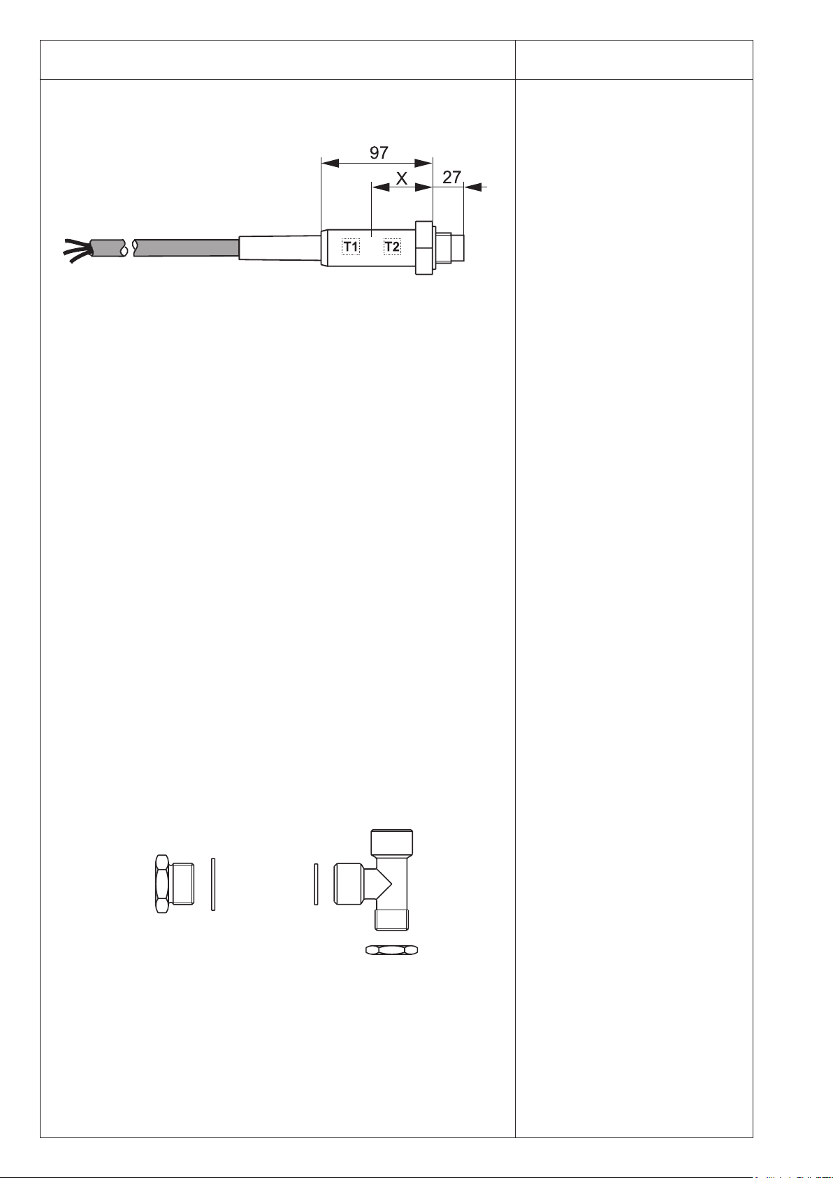
Trace-heating system
The trace-heating system consists of a
distribution module with two exible heat-
ing tapes, which are laid along the piping.
The heating tapes are self-regulating,
which means that the heat output is
adapted to the actual temperature. The
tapes can be shortenedas desired without
aecting the heat output per metre.
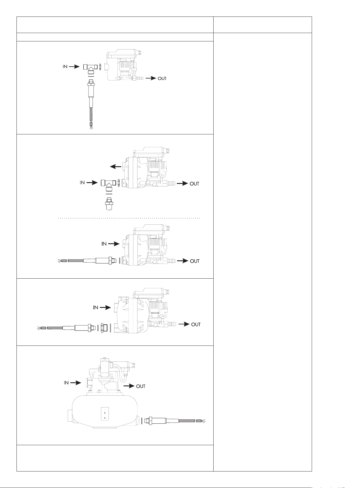
The distribution module (with integrated
ambient temperature sensor) supplies
the power for the heating tapes and has
a free mains outlet.
Scope of delivery:
1 heating tape 3 m (standard)
1 heating tape 1 m (standard)
1 distribution module
incl. installation material
1 xing material
(for wall mounting)
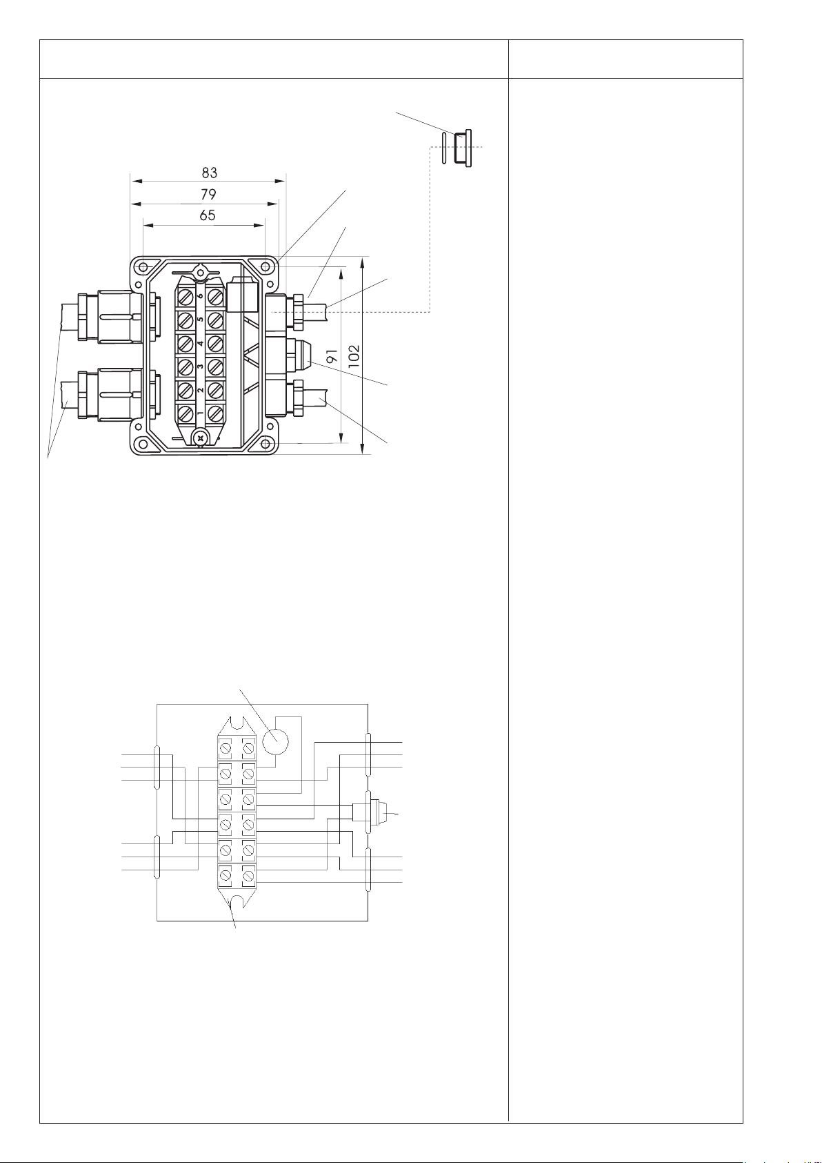
The distribution module includes a
terminal strip, thermostatic switch and
ne-wire fuse.
The thermostatic switch continuously
registers the ambient temperature and
switches on the heating tape, when the
temperature drops below +6° C and
switches it o again at +15° C. After being
switched on, the heating tape automati-
cally regulates its heat output according
to the actual local temperature at the pipe.
The free mains outlet is wired up for
temperature-dependent operation. This
makes it possible to utilize the thermo-
static switch for additionalheating devices
(e.g., for a BEKOMAT®heating unit). See
terminal diagram for installation details.
If the free mains output is to be used
for temperature-independent operation,
connect phase Lto terminal 1(instead
of terminal 5).
Trace heating system 2801233
Heating tape extension 2801232
Système hors-gel conduites
Lesystème hors-gel conduites est consti-
tué d’un module répartiteur avec deux
rubans chauants exibles, à poser le
long des conduites.
Le ruban chauant est à régulation auto-
matique, autrement dit, la puissance de
chaue s’adapte à la température réelle.
Ce ruban peut être raccourci à volonté,
sans pour autant modier sa puissance
calorique au mètre linéaire.
Le module répartiteur (avec sonde de
température ambiante intégrée) assure
l’alimentation des rubans chauants et
ore une sortie d’alimentation secteur
supplémentaire, commandée ou non par
le thermostat.
Matériel livré :
1 ruban chauant, 3 m (standard)
1 ruban chauant, 1 m (standard)
1 module répartiteur,
matériel de montage inclus
1 kit de xation
(pour montage mural)
Dans le module répartiteur sont logés le
bornier de raccordement, le thermostat
ainsi que le fusible.
Le thermostat mesure en permanence
la température environnante. Il met le
ruban chauant sous tension lorsque
la température est inférieure à +6° C et
coupe la tension lorsque la température
est supérieure à +15° C. Lorsqu’ilest sous
tension, le ruban chauant régule auto-
matiquement sa puissance de chaue, et
ceci en fonction de la température locale
réelle au niveau de la tuyauterie.
La sortie secteur libre est commandée
par le thermostat. Elle permet d’alimenter
d’autres systèmes de chauage (p. ex.
système hors-gel pour BEKOMAT®), en
fonction de la température ambiante (voir
schéma de raccordement Installation).
Si la sortie secteur libre doit être utilisée
indépendamment de la température
ambiante (non commandée par le ther-
mostat), la phase Ldoit être raccordée à
la borne 1(au lieu de la borne 5).
Système hors-gel conduites
2801233
Prolongateur de ruban chauant
2801232
Spremljevalno ogrevanje s cevmi
Spremljevalno ogrevanje s cevmi sesta-
vljamodul razdelilnika z dvemaprilagodlji-
vima grelnima trakovoma, ki sta položena
vzdolž cevovodov.
Ogrevalni trak se samodejno uravnava, tj.
toplotna moč se prilagodi dejanski tempe-
raturi. Trak je mogoče poljubno krajšati,
ne da bi se pri tem spremenila toplotna
moč na posamezen meter.
Modul razdelilnika (z vgrajenim tipalom
za temperaturo okolice) grelna trakova
napaja z napetostjo in ponuja prost
omrežni priključek.
Obseg dobave:
1 ogrevalni trak 3 m (standard)
1 ogrevalni trak 1 m (standard)
1 modul razdelilnika vključno z
montažnim materialom
1 pritrdilni material
(zastensko montažo)
V modulu razdelilnika se nahajajo priključ-
na letvica, termostikalo in na varovalka.
Termostikalo nenehno zaznava tempera-
turo okolice in ogrevalni trak vklopi pod
+6 °C, nad +15 °C pa ga ponovno izklopi.
Ogrevalnitrak po vklopu samodejno urav-
nava toplotno moč in sicer v odvisnosti
od lokalne dejanske temperature na
cevovodu.
Prosti omrežni izhod je vezan v odvisno-
sti od temperature. S tem je mogoče s
termostikalom upravljati dodatne ogre-
valne naprave (npr. ogrevalna naprava
BEKOMAT®) (glejte Načrt priključitve,
namestitev).
Če je treba omrežni priključek upravljati
v odvisnosti od temperature, je treba
fazo L priključiti na sponko 1(namesto
na sponko 5).
Spremljevalno ogrevanje s cevmi
2801233
Podaljšanje ogrevalnega traku
2801232