AERMEC VED 030 I User manual

4880985_00-0121
VED_I
INVERTER FAN COILS -VENTILO-CONVECTEURS INVERSEUR
EU, EUW, EUTH, EUTL
110-240 V ~ 50/60Hz
030
040
130
140
230
240
330
340
•

AERMEC S.p.A. reserves the right to make any modifications considered necessary to improve its products at any moment and is not obliged to add these
modifications to machines that have already been manufactured, already delivered or are under construction.
Dear customer,
Thank you for choosing an AERMEC product. This product is the result of many years of experi-
ence and in-depth engineering research, and it is manufactured using top quality materials and
cutting edge technologies.
In addition, the CE mark guarantees that our appliances fully comply with the requirements of
the European Directives in terms of safety. The quality level is under constant surveillance, and
AERMEC products are therefore synonymous with Safety, Quality and Reliability.
Thank you again.
AERMEC S.p.A
index:
important informaon and maintenance............................................. 4
system examples .................................................................................. 5
descripon of the unit.......................................................................... 6
accessories ........................................................................................... 6
main components................................................................................. 7
operang limits .................................................................................... 8
technical data ....................................................................................... 9
pressure drops cooling only ............................................................... 10
2-pipe system pressure drops heang only........................................ 10
4-pipe system pressure drops heang only........................................ 10
ow stac pressure ............................................................................ 11
correcon factors in funconing with glycol water............................12
sound power level expressed in db (a)............................................... 13
informaons importantes et maintenance ........................................ 17
exemples d’installaon....................................................................... 18
descripon de l’unité.......................................................................... 19
accessories ......................................................................................... 19
main components............................................................................... 20
plage de fonconnement ................................................................... 21
donnees techniques ........................................................................... 22
pertes de charge baerie principale à chaud .................................... 23
système à 4 tuyaux chute de pression chauage uniquement ..........23
pertes de charge baerie principale à froid ......................................23
hauteur manométrique au refoulement............................................24
facteurs de correcon pour le fonconnement avec de l’eau glycolée25
niveau de puissance sonore exprimé en db (a) ..................................26
ved 0xx-1xx-2xx-3xx i eu:.................................................................... 32
wiring diagrams • schemas electriques..............................................33

TRASPORTO • TRANSPORT • TRANSPORT • TRANSPORT • TRANSPORTE
NON bagnare. Tenere
al riparo dalla pioggia.
KEEP DRY. Keep out of
the rain.
NE PAS mouiller. Tenir
à l’abri de la pluie.
NICHT nass machen.
Vor Regen geschützt
anbringen
NO mojar. Conservar
protegido de la lluvia.
NON calpestare. DO NOT step on unit. NE PAS marcher sur
l’appareil. NICHT betreten . NO pisar.
N
Sovrapponibilità: con-
trollare sull’imballo per
conoscere il numero di
macchine impilabili.
Stackability: check the
package to know the
number of stackable
machines.
Empilement : vérifier sur
l’emballage le nombre
d’appareils empilables.
Stapelbarkeit: Auf der
Verpackung nachse-
hen, wie die Anzahl
der stapelbaren Geräte
lautet.
Superponibilidad:
observar en el emba-
laje la cantidad de
máquinas que pueden
apilarse.
>25Kg
NON trasportare la
macchina da soli se il
suo peso supera i 25Kg.
DO NOT carry the
equipment alone if
weight exceeds 25Kg.
NE PAS faire transporter
l’appareil par une seule
personne si son poids
est supérieur à 25kg.
NICHT das Gerät allein
transportieren, wenn
sein Gewicht die 25kg
übersteigt.
NO transportar la
máquina solos si su
peso es superior a los
25Kg.
NON lasciare gli imballi
sciolti durante il
trasporto.
Non rovesciare.
DO NOT leave boxes
unsecured during
transportation.
Do not overturn.
NE PAS laisser les
emballages sans
attaches durant le
transport.
Ne pas renverser.
NICHT die
Verpackungen wäh-
rend des Transports
geöffnet lassen.
Nicht stürzen.
NO dejar los embalajes
sin sujetar durante el
transporte.
No invertir.
Fragile, maneggiare
con cura.
Fragile, handle with
care.
Fragile, manipuler avec
soin.
Zerbrechlich, sorgfältig
handhaben.
Frágil, manipular con
cuidado.
Simboli di sicurezza • safety symbol • simboies de SECURITE
Sicherheitssymboleole • Símbolos de seguridad
Pericolo:
Tensione
Danger:
Power supply
Danger:
Tension
Gefahr !
Spannung
Peligro:
Tensión
Pericolo:
Organi in movimento
Danger:
Movings parts
Danger:
Organes en mouve-
ment
Gefahr !
Rotierende Teile
Peligro:
Elementos en
movimiento
Pericolo!!! Danger!!! Danger!!! Gefahr!!! Peligro!!!
Imballo: indicazioni per
trasporto e stoccaggio
Packing: indications for
transport and storage
Emballage: indications
pour le transport et le
stockage
Verpackung:
Anweisungen für
Transport und Lagerung
Embalaje: indicaciones
para el transporte y el
almacenamiento

4IVEDITI 0121 4880985_00
To clean the air filter remove it from the fan
coil.
The clean or new (replaced) air filter must be
mounted and locked in place properly in the
fan coil.
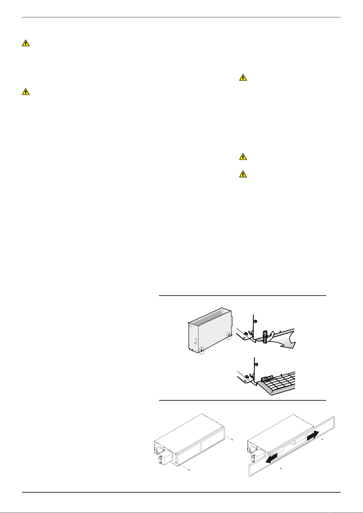
To remove the air filter:
- loosen the screws of the two filter retainers
- make the two filter retainers slide all the
way
- pull the filter out of its seat
To remount the clean air filter:
- insert the air filter into its seat,
- make the two filter retainers slide until
locking the filter in place,
- tighten the screws of the two filter retainers,
- make sure that the filter is locked in place.
ATTENTION:
The fan coil is connected to the power sup-
ply and the hydraulic circuit. Operations
performed by persons who do not have the
required technical skills can lead to personal
injury to the operator or damage the unit
and the surrounding environment.
Supply the fan coil only with voltage 220V
~ 60Hz. The fan coil may be permanently
damaged if a different electric power supply
is used.
The fan coil must not be used to breed, deliv-
er and raise animals.
Periodically air out the room in which the
fan coil has been installed; this is particu-
larly important if the room is occupied by
many people, or if there are gas appliances
or sources of odours.
Ambient temperature should be regulated
to ensure maximum comfort, particularly
for the elderly, infants and invalids. Prevent
temperature fluctuations between indoors
and outdoors greater than 7°C/44.6°F dur-
ing summer. Excessively low temperatures
during summer involve higher electrical con-
sumption.
Air delivered by the fan coil must not be
directed onto people. Even if the air tem-
perature is higher than the ambient tem-
perature, it can cause a cold sensation and,
therefore, discomfort.
DO NOT USE WATER THAT IS TOO HOT
Use soft cloths or sponges soaked in warm
water (no higher than 40 °C/104°F) to clean
the fan coil. Do not use chemical products or
solvents to clean any part of the fan coil. Do
not spray water on internal or external sur-
faces of the fan coil (danger of short circuits).
Frequent cleaning of the filter will ensure
more efficient operation. Check if the filter is
excessively dirty. Repeat the operation more
frequently, if required. Clean often and use a
suction device to remove accumulated dust.
When the filter is clean, reassemble it onto
the fan coil by following the removal proce-
dure in reverse order.
Removing the augers of the inspected fans
(which can be carried out only by qualified
personnel) allows the internal parts to be
cleaned accurately. This is essential for instal-
lation in very crowded areas or that require
high hygienic standards.
Always leave the filter mounted on the fan
coil during operation, otherwise the dust in
the air will dirty the surface of the coil.
When in cooling mode, water vapour can
come out of the fan coil air flow. When in
heating mode, a slight hissing sound can be
heard near the fan coil. The fan coil may
sometimes emit unpleasant odours due to
the accumulation of substances present
in the environment (clean the filter more
often, especially if the room is not aired out
regularly). During operation, noise and/or a
creaking sound may be heard from inside the
device due to the heat expansion of the ele-
ments (plastic and metal), however, this does
not indicate a fault and does not cause dam-
age to the unit unless the maximum input
water temperature is exceeded.
In case of anomalous operation, disconnect
the voltage from the unit and then re-apply it
and re-start the appliance.
ATTENTION! Do not try to repair the unit
on your own, as it may be very dangerous! If
the problem persists, call the Area After-sales
Service immediately.
It is very dangerous to pull, step on or crush
the power supply cable or secure it using
nails or staples. The damaged cable can
cause short circuits and injury to persons.
This could cause injury to persons or dam-
age the fan.
ATTENTION
The appliance can be used by children over
the age of 8 and by people with reduced
physical, sensory or mental capabilities or
without experience or necessary knowledge,
as long as they are supervised or have been
instructed on the safe use of the appliance
and on the understanding of the dangers
inherent to it. Children must not play with
the appliance. Cleaning and maintenance
must be carried out by the user and not by
unsupervised children. Please also note that
the unit must not be used by children as a
toy
only version EU UTH ETL
only version EUW EUWP

5
IVEDITI 0121 4880985_00
The units are designed for installation in closed
environments in 'urban’, non-marine atmos-
phere conditions that are not corrosive or dusty.
The following concentrations of the air polluting
factors where the unit must operate must not
be exceeded under any circumstances:
SO
2
< 0.02 ppm
H
2
S < 0.02 ppm
NO,NO
2
< 1 ppm
NH
3
< 6 ppm
N
2
O < 0.25 ppm
The unit must not be installed in areas char-
acterised by the presence of flammable gases
or acidic or alkaline substances. Otherwise the
coils and the internal components of the equip-
ment might undergo serious and permanent
damage in terms of corrosion.
Warnings for the quality of water circulating in
the coils. We recommend performing an analy-
sis of the water circulating in the coil focused
on searching for any bacteria (detection of iron
bacteria and micro-organisms that can produce
H2S or chemically reduce sulphates) and the
chemical composition of the water itself to pre-
vent corrosion and encrustations inside the
pipes.
The water circuit must have all the components,
such as for instance relief and drainage systems,
shut-off valves and that the results of the analy-
sis performed suggest are necessary to ensure
suitable water treatment. The water treatment
system must ensure compliance with the follow-
ing chemical and physical parameters:
Total hardness in
mmol/l l < mmoll/l < 1.5
Chlorides [CL
-
] < 10 mg/litre
Sulphates [SO
4
2-
] < 30 mg/litre
Nitrates [NO
3
-
] = 0 mg/litre
Dissolved iron < 0.5 mg/litre
Dissolved oxygen 4 < [O
2
] < 9 mg/litre
Carbon dioxide [CO
2
]< 30 mg/litre
Resistivity 20 Ohm∙m < Resistivity < 50 Ohm∙m
pH 6.9 < pH < 8
C/FC VC/FVCC/FC VC/FVCSAVC/FVCSA
VC/FSA C/F
VC/FSA C/F
SA C/F
SA
SW
VC/FVCSA SW VC/FVCSA C/FC
SW VC/F
C/F
VC/FSA SW
C/F
SA SW
C/F
SW
SA
SW
VC/FVCSA SW VC/FVCSA C/FC
SW VC/F
C/F
VC/FSA SW
C/F
SA SW
C/F
SW
SW Water temperature probe
VC/F Valve (Heang / Cooling)
VC Valve (Heang)
SA Room temperature probe
H/C Coil (Heang / Cooling)
CCoil (Heang)
HORIZONTAL INSTALLATION
C/FC VC/FVCC/FC VC/FVCSAVC/FVCSA
VC/FSA C/F
VC/FSA C/F
SA C/F

6IVEDITI 0121 4880985_00
VED 030 I EU-EUTH-EUTL EUW
VED 040 I
EU-EUTH-EUTL EUW
VED 130 I
EU-EUTH-EUTL EUW
VED 140 I
EU-EUTH-EUTL EUW
VED 230 I
EU-EUTH-EUTL EUW
VED 240 I
EU-EUTH-EUTL EUW
VED 330 I
EU-EUTH-EUTL EUW
VED 340 I
EU-EUTH-EUTL EUW
VED 030 I EU-EUTH-EUTL EUW
VED 130 I EU-EUTH-EUTL EUW
VED 230 I EU-EUTH-EUTL EUW
VED 330 I EU-EUTH-EUTL EUW
DESCRIPTION OF THE UNIT
−The fan coil is a terminal used to treat air, both during winter and summer. The VED_I fan coils have been designed to meet any requirement
in ducted systems.
−In particular, the fact that the unit can be integrated in the VMF system allows you to control the individual fan coil with accessories up to the
management of the VED_I inserted in complex networks of fan coils and relative accessories.
The VED_I fan coils are available for:
• Fan coil for vertical wall mounted installa-
tion and horizontal suspended ceiling instal-
lation
• Versions for 2-pipe systems with main,
standard or larger coil.
• Versions for 4-pipe systems with also heat-
ing, standard or larger coil.
• Coil with low pressure drops.
• Reversible connections on site.
• Wide range of accessories to connect the
fan coil to the air ducting.
• It requires an external control device
(accessory).
• Wide range of controls and accessories.
• Wide possibility to have different useful
static pressure.
• Motorised fan with brushless motor and
dedicated inverter.
• Centrifugal fans with blades designed for
low sound emissions
• Filter with G3 filtration class.
• Intake air filter, easy to remove for periodi-
cal cleaning.
variable water flow rate
• Internal insulation class 1.
• Full compliance with accident-prevention
standards.
• Easy installation and maintenance
• Flow flange obtained directly on the unit.
ACCESSORIES
VCF4_C_24V
Kit made up from motorised 3-way valves with
isolang shell, ngs and isolated copper pipes.
For main coils.
24V power supply.
VCF4_H_24V
Kit made up from motorised 3-way valves, ngs
and isolated copper pipes. For heang only coils.
24V power supply.
VCF2_C_24V
Kit made up from motorised 2-way valves, with t-
ngs and isolated copper pipes. For main coils.
24V power supply.
VCF2_H_24V
Kit made up from motorised 2-way valves, with
ngs
and copper pipes. For heang only coils.
24V power supply.
Available in 24V and 120V power supply
(contact Aermec oce for compability).
Single row hot water heat exchanger.
RPA_VUS
is an intake plenum with rectangular ange made of
galvanised sheet steel. This accessory is for connec-
on of a channel with a rectangular secon to the
intake vent of the unit.
According to requirements, the RPA_VUS accessory
allows for intake both longitudinal and perpendicu-
lar to the air ow passing through the unit. The
sides of the RPA_V intake plenum are set for the
connecon of a circular secon channel by means of
the KFVUF accessory.
PA_VUS
is an intake plenum made of galvanised sheet steel
with plasc circular anges having variable secon.
This accessory is for connecon of channels with
circular secon to the intake vent of the unit. Ac-
cording to requirements, the PA_VUS accessory al-
lows for intake both longitudinal and perpendicular
to the air ow passing through the unit.
The sides of the PA_VUS intake plenum are set for
the connecon of an addional circular secon
channel by means of the KFVUS accessory.
:
is a ow plenum with rectangular ange made
of galvanised sheet steel and fully insulated. This
accessory is for connecon of a channel with a
rectangular secon to the ow vent of the unit.
According to requirements, the RPM_V accessory
allows for both longitudinal and perpendicular
delivery to the air ow passing through the unit.
The sides of the RPM_V ow plenum are set for the
connecon of a circular secon channel by means of
the KFV accessory.
is a ow plenum made of galvanised sheet steel,
fully insulated with plasc circular anges having
variable secon. This accessory is for connecon of
channels with circular secon to the ow vent of
the unit. According to requirements, the PM_VUS
accessory allows for both longitudinal and perpen-
dicular delivery to the air ow passing through the
unit. The sides of the PM_VUS ow plenum are set
for the connecon of an addional circular secon
channel by means of the KFVUS accessory.
RDAC_V
is a straight sucon galvanized sheet with circular
anges variable secon plasc. This accessory al-
lows to connect several circular secon channel unit
blowing mouth.
KFV
is an intake/ow circular ange kit with variable
secon, in plasc. This accessory is for connecon
of an addional circular duct, making use of the set-
ups present on the sides of the intake/ow plenum
of the unit.

7
IVEDITI 0121 4880985_00
1. Air delivery
2. Heat exchange coil
3. Water connections
4. Air vents on the coil
5. Condensate drain
6. Tray
7. Air filter (suction)
8. Fan
9. Electric motor | Inverter device
10. Front closure panel
11. Filter clip
12. Electrical wiring
13. Load-bearing structure
1
3
2
13
4
3
4
5
6 8 9
7810 11 12
INVERTER DEVICE
they are designed for 2- and 4-pipe system
with fixed or variable flow rate.
2-pipe system, versions are available with:
- standard main coil;
- larger main coil;
4-pipe system, versions are available with:
- standard main battery + larger hot water
coil for heating only.
- larger main battery + standard hot water
coil for heating only.
- with hot water for heating only supplied
as accessory for versions VED030I, VED130I,
VED230I and VED330I.
VENTILATION
variable speed ventilation must be controlled
with a control device (not included) with
0-10V outputs and features compatible with
the unit. Aermec provides control devices as
accessories.
Coils with low pressure drops, made with
copper pipe and aluminium corrugated lou-
vers, blocked by the mechanical expansion of
the pipes. The collectors are equipped with
female hydraulic connections and air vents
on the upper part of the coil.
Intake air filter, easy to remove for periodical
cleaning.
Made with renewable raw materials, it can
be cleaned with a suction device.
G3 filtration class. Flame behaviour M1 NF F
16-101.
INVERTER CONTROL
The electric motor "brushless with Hall
probes" and the control system used in the
AERMEC VED_I fan coils come from a com-
bination of the most sophisticated technolo-
gies in the field of mechanics and electronics,
and are completely developed within the
industrial group. It is a permanent magnet
motor with low peak current and easily
adjustable speed.
It is not affected by electromagnet interfer-
ence.
The fact that it is brushless means less fric-
tion and reduced wear.
Through the dedicated inverter device it is
possible to continuously control the rotor
speed and torque, by simply acting on the
stator currents.
The electric motor is buffered with elastic
supports and the steel shaft is mounted on
bearings. The resistance to saline mist is
tested according to ASTM B117/64.
The electric motor "brushless with Hall
probes" used in the AERMEC modulating
fan coils shows great advantages compared
to traditional AC motor and to hybrid and
inverter motors (without Hall probes) nor-
mally used on other modulating fan coils:
- Reduced wear
- Option to precisely and continuously adjust
the rotation speed (0-100%)
- Greater energy yield
- Greater reliability and durability
- Low magnetic noise
- Continuous monitoring of the rotor position
implies greater efficiency, and guaranteed
and controlled peak
- Minimum guaranteed speed 90 rpm (for
thermodynamic reasons this limit has been
increased to 200 rpm).
The electric motor is buffered with elastic
supports.
SUPPORT STRUCTURE
It is made with galvanised sheet metal of
suitable thickness. Internal insulation Class 1
Slots are located on the rear side for instal-
lation.
The intake and flow inlets connect the fan
coil to any type of air ducting.
The ventilation unit is closed on the front
with a metal panel.
The flow inlet includes the connection flange.
CONDENSATE DRAIN
Any device is equipped with a condensate
drip tray for vertical and horizontal installa-
tion. The fan coil tray has condensate drains
on the right and left side. We recommend
using the condensate drain fitting placed on
the side of the hydraulic connections.
The connections placed on the left side are
female type. The coil can be rotated to take
the connections to the right side. The coil can
be rotated in the work site.
VED_IXXXEU
VED 030-340 I EU basic inverter 110-240V 50/60Hz
VED 030-340 I EUTH inverter with thermostat interface card 240V 50/60Hz
VED 030-340 I EUTL inverter with thermostat interface card 120V 50/60Hz
VED 030-340 I EUW inverter with disconnector and acquastat management 120/208/240V 50/60Hz (default 120V)

8IVEDITI 0121 4880985_00
If the fan coil runs continuously in cooling
mode in an environment with high relative
humidity, condensate may form on the air
flow outside the appliance. This conden-
sate could drip onto the floor and onto any
underlying objects.
To prevent condensation phenomena on the
external structure of the appliance with the
fan running, the average water tempera-
ture must not drop below the limits indi-
cated in the table. These limits depend on
the temperature and humidity conditions of
the room air.
These limits refer to operation with the fan
running
at minimum speed.
Condensation may form in the event the fan
is off for a prolonged period and cold water
flows in the coil; therefore, we recommend
installing the 3-way valve (accessory).
[°C] [°F]
25 °C / 77 °F
15 °C / 59 °F 3 / 37.4 3 / 37.4 3 / 37.4 3 / 37.4 3 / 37.4 3 / 37.4
3 / 37.4 3 / 37.4 3 / 37.4 3 / 37.4 3 / 37.4 3 / 37.4
3 / 37.4 3 / 37.4 3 / 37.4 3 / 37.4 3 / 37.4 3 / 37.4
6 / 42.8 5 / 41 4 / 39.2 3 / 37.4 3 / 37.4 3 / 37.4
- 8 / 46.4 7 / 44.6 6 / 42.8 5 / 41 5 / 41
The earth leakage current of several devices
placed under the same circuit breaker is
summed, therefore we recommend paying
attention to the calibration value of the cir-
cuit breaker and, if necessary, consider split-
ting the installation in more circuits, each of
which protected by its own circuit breaker.
In order to prevent air stratification in the
environment and thus have a better mix-
ture, the fan coil should not be supplied with
water that is hotter than 149°F.
Using water at a very high temperature can
cause creaking due to the heat expansion
of the elements (plastic and metal), how-
ever, this does not cause damage to the unit
unless the maximum operating temperature
is exceeded.
VED 030I 040I 130I 140I 230I 240I 330I 340I
Maximum recommended water inlet temperature 149
Minimum water flow (Main coil) l/h gpm 0,66 0,66 0,66 0,66 0,66 0,66 1,32 1,76
Maximum water flow (Main coil) l/h gpm 6,60 6,60 6,60 6,60 6,60 6,60 13,21 17,61
Minimum water flow rate (Heating only coil accessory) l/h gpm 0,22 - 0,22 - 0,22 - 0,22 -
Maximum water flow (Heating only coil accessory) l/h gpm 2,20 - 2,20 - 2,20 - 4,40 -

9
IVEDITI 0121 4880985_00
TECHNICAL DATA
VED - 2 PIPE SYSTEMS
030I 040I 130I 140I 230I
Fan speed
H M L H M L H M L H M L H M L
Hating Performance
Heating capacity (70°C/158°F) (1) BTU/h 12.591 11.499 6.210 13.376 12.181 8.087 21.462 19.893 15.013 22.452 20.780 15.423 24.431 22.179 18.255
Water ow rate (1) gpm 1.42 1.30 0.70 1.51 1.38 0.91 2.43 2.25 1.70 2.54 2.35 1.74 2.77 2.51 2.06
Pressure drops (1) psi 1.31 1.02 0.44 1.74 1.45 0.58 3.77 3.19 1.89 2.61 2.32 1.31 5.37 4.35 3.92
Heating capacity (45°C/113°F) (2) BTU/h 6.244 5.732 3.105 6.654 6.074 4.026 10.680 9.895 7.473 11.158 10.339 7.677 12.147 11.021 9.076
Water ow rate (2) gpm 1.40 1.28 0.69 1.49 1.36 0.90 2.39 2.22 1.67 2.50 2.32 1.72 2.72 2.47 2.03
Pressure drops (2) psi 1.31 1.02 0.44 1.74 1.45 0.58 3.63 3.05 1.89 2.47 2.32 1.31 5.22 4.21 3.77
Cooling Performance
Total cooling capacity (3) BTU/h 5.528 4.948 3.378 6.483 5.869 3.822 10.236 9.520 7.097 11.226 10.407 7.746 11.670 10.680 8.837
Sensible cooling capacity
(3) BTU/h 4.231 3.822 2.559 4.606 4.197 2.764 7.131 6.620 4.913 8.087 7.473 5.494 9.213 8.326 6.824
Water ow rate (3) gpm 1.23 1.10 0.75 1.44 1.30 0.85 2.27 2.11 1.58 2.49 2.31 1.72 2.59 2.37 1.96
Pressure drops (3) psi 1.31 1.02 0.44 2.03 1.74 0.73 4.50 3.92 2.18 3.34 2.90 1.60 6.38 5.22 3.63
Fans
Centrifugal
fans
n°
11222
Air ow rate cfm 168 151 95 163 147 94 255 234 169 247 227 165 347 308 245
High static pressure in wg 0.24 0.20 0.08 0.24 0.20 0.08 0.24 0.20 0.10 0.24 0.20 0.11 0.26 0.20 0.13
Sound level
Sound power
dB(A) 54 52 44 54 52 44 55 53 47 55 53 47 57 54 49
Sound pressure (4) dB(A) 50 48 40 50 48 40 50 48 42 50 48 42 52 49 44
Hydraulic connections
Standard coil“female” Ø 3/4" 3/4" 3/4" 3/4" 3/4"
Increased coil“female” Ø-----
Electrical data 220V~60Hz
FLA A 0.36 0.36 0.48 0.48 0.66
Input power W36 29 12 36 29 12 45 33 17 45 33 17 53 40 24
0-10V signal 9V 8,2V 5,4V 9V 8,2V 5,4V 9V 8,2V 5,8V 9V 8,2V 5,8V 9V 8,2V 5,8V
VED - 2 PIPE SYSTEMS
240I 330I 340I
Fan speed
H M L H M L H M L
Hating Performance
Heating capacity (70°C/158°F) (1) BTU/h 26.990 24.363 19.790 35.862 31.869 26.649 37.363 34.190 28.355
Water ow rate (1) gpm 3.06 2.76 2.24 4.06 3.61 3.02 4.23 3.87 3.21
Pressure drops (1) psi 4.64 3.77 2.61 2.32 1.89 1.31 4.64 4.06 3.19
Heating capacity (45°C/113°F) (2) BTU/h 13.410 12.113 9.861 17.846 15.866 13.273 18.596 16.992 14.126
Water ow rate (2) gpm 3.01 2.71 2.21 3.99 3.55 2.97 4.16 3.81 3.16
Pressure drops (2) psi 4.50 3.63 2.47 2.32 1.89 1.31 4.50 3.92 3.05
Cooling Performance
Total cooling capacity (3) BTU/h 13.717 12.386 9.895 17.061 15.082 12.557 18.289 16.344 13.580
Sensible cooling capacity
(3) BTU/h 10.305 9.281 7.507 12.761 11.397 9.554 13.614 12.181 10.066
Water ow rate (3) gpm 3.04 2.75 2.20 3.79 3.35 2.79 4.06 3.63 3.02
Pressure drops (3) psi 5.37 4.50 2.32 2.61 2.03 1.45 3.77 3.05 2.32
Fans
Centrifugal
fans
n°
233
Air ow rate cfm 335 300 239 474 414 337 456 403 331
High static pressure in wg 0.25 0.20 0.13 0.26 0.20 0.13 0.26 0.20 0.14
Sound level
Sound power
dB(A) 57 54 49 58 55 49 58 55 49
Sound pressure (4) dB(A) 52 49 44 54 51 45 54 51 45
Hydraulic connections
Standard coil“female” Ø 3/4" 3/4" 3/4”
Increased coil“female” Ø - - -
Electrical data 220V~60Hz
FLA A 0.66 0.79 0.79
Input power W53 40 24 86 60 35 86 60 35
0-10V signal 9V 7,8V 6,2V 9V 7,8V 6,2V 9V 7,8V 6,6V
VED - 4 PIPE SYSTEMS
030 + BV030 130 + BV130 230 + BV230 330 + BV162
Fan speed
H M L H M L H M L H M L
Hating Performance
Heating capacity (70°C/158°F) (1) BTU/h 6.756 6.347 4.845 11.533 10.953 8.974 13.683 12.727 11.192 17.982 16.754 14.911
Water ow rate (1) gpm 0.77 0.72 0.55 1.30 1.24 1.01 1.55 1.44 1.26 2.03 1.89 1.68
Pressure drops (1) psi 1.02 0.87 0.58 3.34 3.05 2.18 1.89 1.60 1.31 3.05 2.61 2.18
Cooling Performance
Total cooling capacity (3) BTU/h 5.425 4.845 3.344 9.998 9.315 6.927 11.533 10.509 8.735 16.754 14.877 12.454
Sensible cooling capacity
(3) BTU/h 4.163 3.719 2.491 7.404 6.483 4.777 9.110 8.155 6.756 12.557 11.260 9.486
Water ow rate (3) gpm 1.21 1.07 0.75 2.22 2.06 1.54 2.56 2.33 1.94 3.72 3.31 2.77
Pressure drops (3) psi 1.16 0.87 0.58 4.50 3.92 2.18 6.38 5.37 3.77 2.61 2.03 1.45
Fans
Centrifugal
fans
n°
1223
Air ow rate cfm 280 250 160 423 388 280 582 513 412 790 695 568
High static pressure in wg 0.24 0.20 0.08 0.24 0.20 0.10 0.26 0.20 0.13 0.26 0.20 0.13
Sound level
Sound power
dB(A) 54 52 44 55 53 47 57 54 49 58 55 49
Sound pressure (4) dB(A) 50 48 40 50 48 42 52 49 44 54 51 45
Hydraulic connections
Standard coil“female” Ø 3/4" 3/4” 3/4” 3/4”
Additional heat exchanger (BV)
Ø 1/2" 1/2” 1/2” 1/2”
Electrical data 220V~60Hz
FLA A 0.36 0.48 0.66 0.79
PERFORMANCE OF VERSIONS WITH UPGRADED MOTOR REFERS TO THE FOLLOWING CONDITIONS:
(1)
Room air 68°F b.s.; Water (in/out) 158°F/140°F.
(2)
Room air 68°F b.s.; Water (in/out) 113°F/104°F.
(3)
Room air 80.6°F b.s./66.2°F b.u.; Water (in/out) 44.6°F/53.6°F.
(4)
Sound pressure level (weighted A) measured with open port in a 3 and reverberation time of 0.5 seconds room with 3002 ft.

10 IVEDITI 0121 4880985_00
Water flow rate [l/h-gpm]
Water flow rate l/h-gpm]
Coil pressure drops [kPa-ftH2O]
The pressure drops in the previous diagram relate to an average water temperature of 50 °F (10 °C).
The table below states the correction to apply to the pressure drops on variation of the average water temperature.
Water medium temperature °C 5 10 15 20 50 60 70
°F 41 50 59 68 122 140 158
Multiplicative coefficients 1.03 1 0.96 0.91 0.78 0.75 0.72
0
20
40
60
80
100
120
140
0
68
136
205
273
341
409
478
0 200 400 600 800 1000 1200 1400 1600 1800
0 0,881 1,761 2,642 3,522 4,403 5,283 6,164 7,045 7,925
VED 030I
VED 040I
VED 130I
VED 140I
VED 230I
VED 240I
VED 330I
VED 340I
0
10
20
30
40
50
60
70
80
90
0 100 200 300 400 500 600 700
VED 030I
VED 130I
VED 230I
0 0,440 0,881 1,321 1,761 2,201 2,642 3,082
0
34
68
102
136
171
205
239
273
307
0
20
40
60
80
100
120
0 200 400 600 800 1000 1200 1400 1600 1800
VED 030I
VED 040I
VED 130I
VED 140I
VED 230I
VED 240I
VED 330I
VED 340I
0
0 0,881 1,761 2,642 3,522 4,403 5,283 6,164 7,045
7,925
68
136
205
273
341
409
The pressure drops in the previous diagram relate to an average water temperature of 50 °F (10 °C).
The table below states the correction to apply to the pressure drops on variation of the average water temperature.
Water medium temperature °C 41 50 59 68 122 140 158
°F 105 122 138 154 251 284 316
Water medium temperature 1.03 1 0.96 0.91 0.78 0.75 0.72

11
IVEDITI 0121 4880985_00
The tables express the useful static pressure at flow and the input power of
the VED_I fan coils based on the air flow rate and speed of the fan coil, the
speeds refer to 4 power supply voltages.
The motor is set, via the dip switches, to work with the speed increased.
Speed increased: To allow adjusting the static pressure provided by the fan coil
to the duct pressure drops, only on VED_I fan coils it is possible to increase
maximum speed by modifying the settings of the motor dip switches (see
"Installation information" chapter).
FLOW STATIC PRESSURE
VED 030I
VED 040I
VED 240I
VED 230I
VED 130I
VED140I
VED 340I
VED 330I
Air flow rate [m3/h-cfm]
Input [Pa-psi]
Input [Pa-psi]Input [Pa-psi]
Input [Pa-psi]
Input [Pa-psi]
Input [Pa-psi]
Input [Pa-psi]
Input [Pa-psi]
VED030I
0
20
40
60
80
100
120
0
0,0029
0,0058
0,0087
0,0116
0,0145
0,0174
0 100 200 300 400 500 600
0 59 118 177 325 294 353
2 V
5 V
7 V
9 V
0
20
40
60
80
100
120
0 200 400 600 800 1000
VED130I
7 V
9 V
5 V
2 V
0
0,0029
0,0058
0,0087
0,0116
0,0145
0,0174
0 118 235 353 471 589
VED230I
0
20
40
60
80
100
120
0 200 400 600 800 1000 120
0
7 V
9 V
5 V
2 V
0
0,0029
0,0058
0,0087
0,0116
0,0145
0,0174
0 118 235 353 471 589 706
VED330I
0
20
40
60
80
100
120
140
0 500 1000 1500
2 V
5 V
7 V
9 V
0
0,0029
0,0058
0,0087
0,0116
0,0145
0,0174
0,0203
0 294 589 883
0
20
40
60
80
100
120
0 100 200 300 400 500 600
VED040I
2 V
5 V
7 V
9 V
0 59 118 177 325 294 353
0
0,0029
0,0058
0,0087
0,0116
0,0145
0,0174
0
20
40
60
80
100
120
140
0 200 400 600 800 1000
VED140I
2 V
5 V
7 V
9 V
0
0,0029
0,0058
0,0087
0,0116
0,0145
0,0174
0,0203
0 118 235 353 471 589
0
20
40
60
80
100
120
0 200 400 600 800 1000 1200
VED240I
2 V
5 V
7 V
9 V
0 118 235 353 471 589 706
0
0,0029
0,0058
0,0087
0,0116
0,0145
0,0174
VED340I
0
20
40
60
80
100
120
140
0 500 1000 1500
0 294 589 883
2 V
5 V
7 V
9 V
0
0,0029
0,0058
0,0087
0,0116
0,0145
0,0174
0,0203

12 IVEDITI 0121 4880985_00
°
f
636159575554525048464543
Average glycol water temperature
Corrective factor
Pressure drops
Flow rate
Yield
°f
636159575554525048464543
Average glycol water temperature
Corrective factor
°f
63 64
6159575554525048464543
Average glycol water temperature
Corrective factor
°f
19486 104 122 140 158 176
Average glycol water temperature
Corrective factor
°
f
19486 104 122 140 158 176
Average glycol water temperature
Corrective factor
°f
19486 104 122 140 158 176
Average glycol water temperature
Corrective factor

13
IVEDITI 0121 4880985_00
VED 030-40 I
Lw2 Lw1 Lw2 Lw1 Lw2 Lw1
Hz
100 39.4 35.6 37.0 37.1 33.2 34.9 28.4 24.8 26.0
125 38.0 36.2 33.2 35.8 34.0 31.1 27.4 25.8 22.4
160 38.9 38.1 31.1 36.9 36.0 29.6 29.1 28.2 21.6
200 40.5 39.5 33.5 38.6 37.7 31.6 31.6 30.5 24.9
250 44.1 43.2 36.7 42.4 41.5 35.3 35.6 34.7 28.3
315 47.2 45.7 41.9 45.6 44.0 40.4 38.1 36.7 32.5
400 49.4 48.0 43.8 47.3 45.9 41.8 39.3 38.0 33.4
500 47.0 45.5 41.9 44.9 43.3 39.7 37.1 35.3 32.2
630 44.5 42.8 39.7 42.6 40.9 37.8 36.3 34.1 32.3
800 45.3 43.5 40.6 43.6 41.8 39.0 32.1 30.4 27.2
1000 42.9 42.0 35.7 40.4 39.5 33.1 31.1 30.2 23.5
1250 39.9 38.5 34.5 37.4 36.0 31.9 27.5 26.2 21.6
1600 35.3 34.0 29.5 32.7 31.4 27.0 21.9 20.6 16.2
2000 34.0 32.6 28.4 31.2 29.8 25.6 19.4 18.0 13.9
2500 31.5 30.1 26.0 28.3 26.8 23.0 15.7 14.1 10.8
3150 28.3 26.6 23.6 25.1 23.2 20.6 12.6 10.6 8.3
4000 24.1 22.7 18.4 20.6 19.3 14.9 6.8 5.4 5.4
5000 21.4 20.4 14.5 17.7 16.9 10.1 5.0 3.7 3.7
6300 17.4 16.4 10.3 13.8 13.0 6.0 5.6 3.5 3.5
8000 13.0 11.6 7.4 9.8 8.1 4.8 7.5 4.9 4.9
10000 11.9 8.6 9.1 10.9 8.0 7.9 11.2 8.5 8.5
54 52 44 40
Key:
Total sound power level
Lw1: Sound power level emitted by the unit flow
Lw2: Power sound level emitted by the unit and suction side
SOUND PRESSURE LEVEL
Sound pressure level (weighted A) measured in environment with volume V=85 m3, reverberation time t=05s, directivity factor Q=2,
distance r=2.5m
VED 030 - 040 I
Lw2 Lw1 Lw2 Lw1 Lw2 Lw1
37.0 35.5 31.5 35.0 33.5 29.5 27.0 25.5 21.5
Lw2
Lw2
Lw2
Lw1

14 IVEDITI 0121 4880985_00
VED 130-140 I
Lw2 Lw1 Lw2 Lw1 Lw2 Lw1
Hz
100 39.8 36.6 37.0 37.5 34,2 34.8 30.9 27.8 28.0
125 38.7 37.2 33.2 36.5 35,0 31.0 30.1 28.8 24.4
160 39.8 39.1 31.1 37.7 37,0 29.5 31.9 31.2 23.6
200 41.3 40.5 33.5 39.4 38,7 31.5 34.4 33.5 26.9
250 44.9 44.2 36.7 43.3 42,5 35.2 38.4 37.7 30.3
315 48.0 46.7 41.9 46.3 45,0 40.3 40.8 39.7 34.5
400 50.2 49.0 43.8 48.0 46,9 41.7 42.0 41.0 35.4
500 47.8 46.5 41.9 45.6 44,3 39.6 39.8 38.3 34.2
630 45.2 43.8 39.7 43.3 41,9 37.7 38.9 37.1 34.3
800 46.0 44.5 40.6 44.3 42,8 38.9 34.8 33.4 29.2
1000 43.8 43.0 35.7 41.2 40,5 33.0 33.9 33.2 25.5
1250 40.7 39.5 34.5 38.1 37,0 31.8 30.3 29.2 23.6
1600 36.1 35.0 29.5 33.5 32,4 26.9 24.7 23.6 18.2
2000 34.8 33.6 28.4 31.9 30,8 25.5 22.2 21.0 15.9
2500 32.3 31.1 26.0 29.0 27,8 22.9 18.5 17.1 12.8
3150 29.0 27.6 23.6 25.8 24,2 20.5 15.2 13.6 10.3
4000 24.8 23.7 18.4 21.4 20,3 14.8 10.9 8.4 7.4
5000 22.2 21.4 14.5 18.6 17,9 10.0 9.2 6.7 5.7
6300 18.2 17.4 10.3 14.6 14,0 5.9 9.0 6.5 5.5
8000 13.7 12.6 7.4 10.5 9,1 4.7 10.4 7.9 6.9
10000 12.4 9.6 9.1 11.4 9,0 7.8 14.0 11.5 10.5
53,0
Key:
Total sound power level
Lw1: Sound power level emitted by the unit flow
Lw2: Power sound level emitted by the unit and suction side
Sound pressure level (weighted A) measured in environment with volume V=85 m3, reverberation time t=05s, directivity factor Q=2,
distance r=2.5m
VED 130 - 140 I
Lw2 Lw1 Lw2 Lw1 Lw2 Lw1
37.7 36.5 31.5 30.7 24.5 29.5 29.7 28.5 23.5
Lw2
Lw2
Lw2
Lw1

15
IVEDITI 0121 4880985_00
VED 230-240 I
Lw2 Lw1 Lw2 Lw1 Lw2 Lw1
Hz
100 41.8 38.6 39.0 38.5 35.2 35.8 32.9 29.8 30.0
125 40.7 39.2 35.2 37.5 36.0 32.0 32.1 30.8 26.4
160 41.8 41.1 33.1 38.7 38.0 30.5 33.9 33.2 25.6
200 43.3 42.5 35.5 40.4 39.7 32.5 36.4 35.5 28.9
250 46.9 46.2 38.7 44.3 43.5 36.2 40.4 39.7 32.3
315 50.0 48.7 43.9 47.3 46.0 41.3 42.8 41.7 36.5
400 52.2 51.0 45.8 49.0 47.9 42.7 44.0 43.0 37.4
500 49.8 48.5 43.9 46.6 45.3 40.6 41.8 40.3 36.2
630 47.2 45.8 41.7 44.3 42.9 38.7 40.9 39.1 36.3
800 48.0 46.5 42.6 45.3 43.8 39.9 36.8 35.4 31.2
1000 45.8 45.0 37.7 42.2 41.5 34.0 35.9 35.2 27.5
1250 42.7 41.5 36.5 39.1 38.0 32.8 32.3 31.2 25.6
1600 38.1 37.0 31.5 34.5 33.4 27.9 26.7 25.6 20.2
2000 36.8 35.6 30.4 32.9 31.8 26.5 24.2 23.0 17.9
2500 34.3 33.1 28.0 30.0 28.8 23.9 20.5 19.1 14.8
3150 31.0 29.6 25.6 26.8 25.2 21.5 17.2 15.6 12.3
4000 26.8 25.7 20.4 22.4 21.3 15.8 12.9 10.4 9.4
5000 24.2 23.4 16.5 19.6 18.9 11.0 11.2 8.7 7.7
6300 20.2 19.4 12.3 15.6 15.0 6.9 11.0 8.5 7.5
8000 15.7 14.6 9.4 11.5 10.1 5.7 12.4 9.9 8.9
10000 14.4 11.6 11.1 12.4 10.0 8.8 16.0 13.5 12.5
Key:
Total sound power level
Lw1: Sound power level emitted by the unit flow
Lw2: Power sound level emitted by the unit and suction side
Sound pressure level (weighted A) measured in environment with volume V=85 m3, reverberation time t=05s, directivity factor Q=2,
distance r=2.5m
VED 230 - 240 I
Lw2 Lw1 Lw2 Lw1 Lw2 Lw1
39.7 38.5 33.5 36.7 35.5 30.5 31.7 30.5 25.5
Lw2
Lw2
Lw2
Lw1

16 IVEDITI 0121 4880985_00
Key:
Total sound power level
Lw1: Sound power level emitted by the unit flow
Lw2: Power sound level emitted by the unit and suction side
Lw2
Lw2
Lw2
Lw1
VED 330-340 I
Maximale Moyenne Minimale
Fréquence Tot. Lw2 Lw1 Tot. Lw2 Lw1 Tot. Lw2 Lw1
Hz dB[A] dB[A] dB[A] dB[A] dB[A] dB[A] dB[A] dB[A] dB[A]
100 43,4 39,6 41,0 40,1 36,2 37,8 22,4 18,8 20,0
125 42,0 40,2 37,2 38,8 37,0 34,0 21,4 19,8 16,4
160 42,9 42,1 35,1 39,9 39,0 32,5 23,1 22,2 15,6
200 44,5 43,5 37,5 41,6 40,7 34,5 25,6 24,5 18,9
250 48,1 47,2 40,7 45,4 44,5 38,2 29,6 28,7 22,3
315 51,2 49,7 45,9 48,5 47,0 43,3 32,1 30,7 26,5
400 53,4 52,0 47,8 50,3 48,9 44,7 33,3 32,0 27,4
500 51,0 49,5 45,9 47,8 46,3 42,6 31,1 29,3 26,2
630 48,5 46,8 43,7 45,6 43,9 40,7 30,3 28,1 26,3
800 49,3 47,5 44,6 46,6 44,8 41,9 26,1 24,4 21,2
1000 46,9 46,0 39,7 43,3 42,5 36,0 25,1 24,2 17,5
1250 43,9 42,5 38,5 40,4 39,0 34,8 21,5 20,2 15,6
1600 39,3 38,0 33,5 35,7 34,4 29,9 15,9 14,6 10,2
2000 38,0 36,6 32,4 34,2 32,8 28,5 13,4 12,0 7,9
2500 35,5 34,1 30,0 31,2 29,8 25,9 9,7 8,1 4,8
3150 32,3 30,6 27,6 28,1 26,2 23,5 6,6 4,6 2,3
4000 28,1 26,7 22,4 23,6 22,3 17,8 6,4 2,5 4,2
5000 25,4 24,4 18,5 20,7 19,9 13,0 6,6 3,5 3,6
6300 21,4 20,4 14,3 16,8 16,0 8,9 7,3 4,0 4,6
8000 17,0 15,6 11,4 12,8 11,1 7,7 9,1 6,0 6,1
10000 15,9 12,6 13,1 13,9 11,0 10,8 9,3 7,0 5,5
dB[A] tot. 59,5 58,0 54,0 56,4 55,0 51,0 39,5 38,0 34,0
Sound pressure level (weighted A) measured in environment with volume V=85 m3, reverberation time t=05s, directivity factor Q=2,
distance r=2.5m
VED 330-340 I
Lw2 Lw1 Lw2 Lw1 Lw2 Lw1
78 58 54 56,4 55 51 39,5 38 34

17
IVEDITI 0121 4880985_00
ATTENTION : le ventilo-convecteur est bran-
ché au réseau électrique et au circuit hydraulique,
une intervention effectuée par un personnel
dépourvu des compétences techniques spéci-
fiques peut provoquer des dommages à lui-même,
à l'appareil et au milieu environnant.
Alimenter le ventilo-convecteur seulement
avec une tension 220V ~ 60Hz
Des alimentations électriques différentes peuvent
endommager le ventilo-convecteur de façon irré-
parable.
Le ventilo-convecteur ne doit pas être utilisé pour
élever, faire naître et faire grandir des animaux.
AÉRER L'ESPACE
Il est conseillé d'aérer périodiquement le local où
le convecteur à ventilation est installé, spéciale-
ment si plusieurs personnes se trouvent dans la
pièce ou s'il y a des appareils à gaz ou des sources
d'odeurs.
La température ambiante doit être réglée de
façon à permettre le plus grand bien-être des
personnes présentes, spécialement s'il s'agit de
personnes âgées, d'enfants ou de malades, en évi-
tant les écarts de température entre l'intérieur et
l'extérieur de plus de 7°C/44.6°F en été.
Une température trop basse en été implique de
plus grandes consommations électriques.
L'air qui sort du convecteur à ventilation ne doit
pas investir directement les personnes ; cela peut
en effet provoquer une sensation de froid et, par
conséquent, de gêne, même si l'air est à une tem-
pérature supérieure à la température ambiante.
NE PAS UTILISER D'EAU TROP CHAUDE
Pour nettoyer le ventilo-convecteur, utiliser des
chiffons ou des éponges souples imprégnés d'eau
à une température maximale de 40 °C/104°F. Ne
pas utiliser de produits chimiques ou de solvants
sur aucune partie du ventilo-convecteur. Ne pas
pulvériser de l'eau sur les surfaces externes ou
internes du ventilo-convecteur (cela pourrait pro-
voquer des courts-circuits).
Un nettoyage fréquent du filtre garantit une plus
grande efficacité de fonctionnement.
Contrôler si le filtre est très sale: dans ce cas répé-
ter l'opération plus souvent.
Nettoyer fréquemment, éliminer la poussière
accumulée avec un aspirateur.
Quand le filtre est propre, le remonter sur le ven-
tilo-convecteur en procédant dans le sens inverse
de celui utilisé pour le démontage.
La possibilité de retirer les vis sans fin des ven-
tilateurs pouvant être inspectées (à n'effectuer
que par du personnel doté de compétence tech-
nique spécifique) permet d'effectuer un nettoyage
soigné également de l'intérieur. Cette condition
est indispensable pour des installations dans des
milieux très fréquentés ou qui exigent des stan-
dards d'hygiène élevés.
Laisser toujours le filtre monté sur le venti-
lo-convecteur durant le fonctionnement sinon la
poussière présente dans l'air salit les surfaces de
la batterie.
Au cours du fonctionnement en mode rafraîchis-
sement, de la vapeur aqueuse peut s'échapper
par le refoulement du ventilo-convecteur.
Au cours du fonctionnement en mode chauf-
fage, un léger bruissement d'air peut être perçu à
proximité du ventilo-convecteur. Le convecteur à
ventilation peut parfois dégager des odeurs désa-
gréables, dues à l'accumulation de substances
présentes dans l'air environnant (spécialement si
l'on n'aère pas régulièrement la pièce, nettoyer le
filtre plus fréquemment).
Au cours du fonctionnement, il est possible de
percevoir des bruits et des craquements à l'inté-
rieur de l'appareil dus aux différentes dilatations
thermiques des éléments (plastiques et métal-
liques), ceci n'indique cependant pas un dysfonc-
tionnement et n'endommage pas l'unité si la tem-
pérature maximale de l'eau en entrée n'est pas
dépassée.
En cas de fonctionnement anormal, couper le cou-
rant à l'unité, ensuite le rebrancher et procéder
au redémarrage de l'appareil.
ATTENTION ! Ne pas tenter de réparer l'unité
soi-même, cela est extrêmement dangereux !
Si le problème se représente, s'adresser rapide-
ment au Service d'Assistance local.
Ne pas tirer sur le câble électrique
Il est très dangereux de tirer, de piétiner, d'écraser
ou de fixer le câble d'alimentation électrique avec
des clous ou des punaises.
Le câble endommagé peut provoquer des
courts-circuits et blesser les personnes.
Ne jamais introduire aucun objet dans la sortie
de l'air.
Ne jamais introduire aucun objet dans la bouche
de refoulement et de sortie de l'air.
Ceci pourrait blesser les personnes et endom-
mager le ventilateur.
ATTENTION
Éviter que des enfants ou des personnes handica-
pées utilisent l'appareil sans surveillance. De plus,
nous rappelons que l'appareil n'est pas un jouet
et donc que les enfants ne doivent pas s'en servir
pour jouer.
RETRAIT ET REMONTAGE DU FILTRE À AIR
Pour nettoyer le filtre à air, il faut le retirer du
ventilo-convecteur.
Le filtre à air propre ou neuf (pour
remplacement), doit être monté et bloqué
correctement dans son logement dans le
ventilo-convecteur.
Pour enlever le filtre à air :
- desserrer les vis des deux dispositifs
blocage filtre
- faire coulisser les deux dispositifs blocage
jusqu’en butée
- enlever le filtre de son logement
Pour remonter le filtre à air propre :
- insérer le filtre à air dans son logement,
- faire coulisser les deux dispositifs blocage
filtre jusqu’à bloquer le filtre,
- serrer les vis des deux dispositifs blocage
filtre,
- s’assurer que le filtre soit bloqué dans son
logement.
only version EU UTH ETL
only version EUW EUWP

18 IVEDITI 0121 4880985_00
Les unités ont été conçues pour être installées dans des milieux fermés
en conditions d’atmosphère « urbaine » non marine et ayant des carac-
téristiques non corrosives et non poussiéreuses.
Les concentrations suivantes de facteurs polluants dans l’air où l’unité
doit opérer ne doivent être dépasséeds en aucun cas :
SO2<0,02 ppm
H2S <0,02 ppm
NO,NO2<1 ppm
NH3<6 ppm
N2O <0,25 ppm
L’unité ne doit pas être installée à des endroits caractérisés par la pré-
sence de gaz inflammables ou de substances à caractère acide ou alca-
lin. Dans le cas contraire, les batteries et les composants internes des
appareils pourraient subir de graves dégâts de corrosion irréparables.
Mises en garde pour la qualité de l’eau circulant dans les batteries. Il
est conseillé de faire effectuer une analyse de l’eau circulant dans la
batterie focalisée sur la recherche de la présence éventuelle de bac-
téries (relèvement des bactéries du fer et des microorganismes qui
peuvent produire H2S ou réduire chimiquement les sulfates) et sur la
composition chimique de l’eau en question de façon à prévenir l’ins-
tauration des phénomènes de corrosion et d’incrustation de l’intérieur
des tuyaux.
Le circuit de l’eau doit être équipé de tous les composants comme par
exemple des systèmes de purge et de drainage, vannes d’arrêt et que
les résultats des analyses effectuées estiment nécessaires pour un bon
traitement des eaux. Le système de traitement de l’eau doit pouvoir
garantir le respect des paramètres chimiques et physiques suivants :
Total hardness in mmol/l l < mmoll/l < 1.5
Chlorides [CL -] < 10 mg/litre
Sulphates [SO4
2-] < 30 mg/litre
Nitrates [NO3
-] = 0 mg/litre
Dissolved iron < 0.5 mg/litre
Dissolved oxygen 4 < [O2] < 9 mg/litre
Carbon dioxide [CO2] < 30 mg/litre
Resistivity 20 Ohm∙m < Resistivity < 50 Ohm∙m
pH 6.9 < pH < 8
SA
SW
VC/FVCSA SW VC/FVCSA C/FC
SW VC/F
C/F
VC/FSA SW
C/F
SA SW
C/F
SW
C/FC VC/FVCC/FC VC/FVCSAVC/FVCSA
VC/FSA C/F
VC/FSA C/F
SA C/F
SW Sonde de température de l'eau
VC/F Vanne (Chauage / Rafraîchissement)
VC Vanne (Chauage)
SA Sonde température ambiante
C/F Baerie (Chauage / Rafraîchissement)
C Baerie (Chauage)

19
IVEDITI 0121 4880985_00
VED 030 I EU-EUTH-EUTL EUW
VED 040 I
EU-EUTH-EUTL EUW
VED 130 I
EU-EUTH-EUTL EUW
VED 140 I
EU-EUTH-EUTL EUW
VED 230 I
EU-EUTH-EUTL EUW
VED 240 I
EU-EUTH-EUTL EUW
VED 330 I
EU-EUTH-EUTL EUW
VED 340 I
EU-EUTH-EUTL EUW
VED 030 I EU-EUTH-EUTL EUW
VED 130 I EU-EUTH-EUTL EUW
VED 230 I EU-EUTH-EUTL EUW
VED 330 I EU-EUTH-EUTL EUW
DESCRIPTION DE L'UNITÉ
− Le ventilo-convecteur est un terminal est destiné au traitement de l'air dans un espace aussi bien en été qu'en hiver. Les ventilo-convecteurs
VED_I, sont conçus pour s'adapter à n'importe quelle exigence dans les installations de type canalisé.
− La possibilité d'être intégré au système VMF permet en particulier le contrôle du simple ventilo-convecteur avec accessoires jusqu'à la gestion
du ventilo-convecteur inséré dans des réseaux complexes.
Les ventilo-convecteurs de la série VED_I sont disponibles pour :
• Ventilo-convecteur pour installation aussi bien
verticale murale qu'horizontale au faux plafond.
• Versions pour des installaons à 2 tuyaux avec
batterie principale standard ou plus puissante.
• Versions pour des installaons à 4 tuyaux avec
aussi batterie chauffage seulement standard ou
plus puissante.
• Batteries avec faibles pertes de charge.
• Raccords réversibles sur le chantier.
• Vaste gamme d'accessoires pour raccorder le
ventilo-convecteur à tous les types de canalisation
de l'air.
• Nécessité d'un disposif de contrôle externe
(accessoire).
• Prévu pour introduction dans le système VMF.
•Vaste gamme de contrôle et accessoires.
• Plusieurs possibilités d'avoir différentes hauteurs
manométriques utiles.
• Motoventilateur avec moteur sans balais avec
inverseur dédié.
• Ventilateurs centrifuges avec hélices conçues
pour une faible émission de bruit.
• Filtre classe de filtrage G3.
• Filtre de l'air à l'aspiration, facile à extraire pour
le nettoyage périodique.
• Accessoires vannes à 3 voies 4 raccords.
• Accessoires vannes à 2 voies pour les installa-
tions à débit d'eau variable.
• Isolant interne classe 1.
• Respect total des normes de protection contre
les accidents.
• Installation et maintenance facilitées.
• Bride de refoulement placée directement sur
l'unité.
VCF4_C_24V
Kit composé de vannes 3 voies motorisées avec coque
isolante, raccords et tubes cuivre isolés. Pour les bobines
principales.Alimentaon 24V.
VCF4_H_24V
Kit made up from motorised 3-way valves, ngs and
isolated copper pipes. For heang only coils. 24V power
supply.
VCF2_C_24V
Kit composé de vannes 2 voies motorisées, avec raccords
et tuyaux en cuivre isolés. Pour les bobines principales.
Alimentaon 24V.
VCF2_H_24V
Kit composé de vannes 2 voies motorisées, avec raccords
et tuyaux en cuivre. Pour le chauage uniquement des
serpenns. Alimentaon 24V.
Panneaux de contrôle
Disponible en alimentaon 24V et 120V
(contacter le bureau Aermec pour la compabilité).
Échangeur de chaleur à eau chaude à une rangée.
RPA_V
Est un plenum d’aspiraon avec bride rectangulaire, réa-
lisé en tôle zinguée. Cet accessoire permet de raccorder
le canal de secon rectangulaire à la bouche d’aspiraon
de l’unité VED_I. L’accessoire RPA_V permet l’aspiraon
longitudinale et perpendiculaire au ux d’air qui traverse
l’unité, selon les nécessités de l’installaon. Le anc du
plenum d’aspiraon RPA_V a la prédisposion pour le
raccordement d’un canal de secon circulaire au moyen
de l’accessoire KFV.
PA_VUS
Est un plenum d’aspiraon réalisé en tôle galvanisée avec
brides circulaires à secon variable en maère plasque.
Cet accessoire permet de raccorder les canaux de secon
circulaire à la bouche d’aspiraon de l’unité. L’accessoire
PA_V permet l’aspiraon longitudinale et perpendiculaire
au ux d’air qui traverse l’unité, selon les nécessités de
l’installaon. Le anc du plenum d’aspiraon PA_V a la
prédisposion pour le raccordement d’un autre canal de
secon circulaire au moyen de l’accessoire KFV
Est un plenum de souage avec bride rectangulaire,
réalisé en en tôle galvanisée, avec isolaon interne.
Cet accessoire permet de raccorder le canal de secon
rectangulaire à la bouche de souage de lunité VED_I.
L’accessoire RPM_V permet le souage longitudinal et
perpendiculaire au ux d’air qui traverse l’unité VED_I, se-
lon les nécessités de l’installaon. Le anc du plenum de
souage RPM_V a la prédisposion pour le raccordement
d’un canal de secon circulaire au moyen de l’accessoire
KFV.
Est un plenum de souage réalisé en tôle galvanisée,
doté d’isolaon interne avec brides circulaires à secon
variable en maère plasque. Cet accessoire permet de
raccorder les canaux de secon circulaire à la bouche de
souage de lunité. L’accessoire PM_V permet le souage
longitudinal et perpendiculaire au ux d’air qui traverse
l’unité, selon les nécessités de l’installaon. Le anc du
plenum de souage PM_VUS a la prédisposion pour le
raccordement d’un canal de secon circulaire supplémen-
taire au moyen de l’accessoire KFV.
RDAC_V
est un raccord droit d’aspiraon en tôle zinguée, avec
brides circulaires à secon variable en plasque. Cet ac-
cessoire permet de raccorder plusieurs canaux de secon
circulaire à la bouche de souage de l’unité.
ACCESSORIES

20 IVEDITI 0121 4880985_00
ont été conçus pour des installations à 2 et 4 tuyaux,
à débit fixe ou variable.
Les installations à 2 tuyaux sont disponibles dans les
versions avec :
- batterie principale standard ;
- batterie principale plus puissante ;
Les installations à 4 tuyaux sont disponibles dans les
versions avec :
- batterie principale standard + batterie plus puis-
sante à eau chaude pour chauffage seulement.
- batterie principale plus puissante + batterie stan-
dard à eau chaude pour chauffage seulement.
- à eau chaude pour chauffage seulement fournie
comme accessoire pour les versions VED030I,
VED130I, VED230I et VED330I.
VENTILATION
La ventilation à vitesse variable doit être contrôlée
avec un dispositif de contrôle (non compris) avec
sorties 0-10V et caractéristiques compatibles avec
l'unité. Aermec met à disposition les dispositifs de
contrôle comme accessoires.
Batterie à faible perte de charge, en tuyau de cuivre
et ailettage en aluminium ondulé, bloquée par
expansion mécanique des tuyaux. Les collecteurs
sont pourvus de raccordements hydrauliques
femelles et d'évents dans la partie haute de la bat-
terie.
SECTION FILTRANTE
Filtre de l'air à l'aspiration, facile à extraire pour le
nettoyage périodique.
Réalisé avec des matériaux renouvelables et peut
être nettoyé avec un aspirateur.
Filtre classe de filtrage G3. Comportement à la
flamme M1 NF F 16-101.
CONTRÔLE INVERSEUR
Le moteur électrique "sans balai avec sondes à effet
Hall" et le système de contrôle utilisé dans les ven-
tilo-convecteurs VED_I d'AERMEC naît de la fusion
des technologies les plus sophistiquées dans le
secteur de la mécanique et de l'électronique entiè-
rement développées au sein du groupe industriel.
Il s'agit d'un moteur à aimants permanents, à faible
courant initial de démarrage et à vitesse facilement
réglable.
Il n'est pas dérangé par les perturbations électroma-
gnétiques.
Le fait qu'il soit sans balai permet des frottements
mineurs et une réduction de l'usure.
Le dispositif inverseur dédié permet de contrôler la
vitesse et le couple du rotor de manière continue,
tout simplement en intervenant sur les courants de
stator.
Le moteur électrique est amorti par l'intermédiaire
de supports élastiques et l'arbre en acier est monté
sur des coussinets, la résistance au brouillard
salin est testée conformément aux normes ASTM
B117/64.
Le moteur électrique "sans balai avec sondes à effet
Hall" utilisé dans les ventilo-convecteurs modulants
d'AERMEC présente de très gros avantages par
rapport aux moteurs traditionnels à courant alterné
et aux moteurs hybrides et inverseur (sans sondes à
effet Hall) généralement utilisés sur d'autres ventilo-
convecteurs modulants :
- Réduction de l'usure
- Possibilité de régler la vitesse de rotation de
manière précise et continue (0-100%)
- Rendement énergétique supérieur
- Fiabilité et durée supérieures
- Bruit magnétique faible
- Contrôle continu de la position du rotor ce qui
garantit une efficacité supérieure et une vitesse de
démarrage garantie et contrôlée
-Vitesse minimum garantie 90 rpm (pour des raisons
thermodynamiques cette limite a été portée à 200
rpm).
le moteur électrique est amorti avec des supports
élastiques
STRUCTURE PORTANTE
Elle est réalisée en tôle zinguée d'épaisseur appro-
priée. Isolant interne Classe1.
Les ouvertures pour l'installation se trouvent à
l'arrière.
Les bouches d'aspiration et de refoulement sont
réalisées pour raccorder le ventilo-convecteur à tous
les types de canalisation de l'air.
Le groupe de ventilation est fermé sur le devant par
un panneau métallique.
La bouche de refoulement comprend la bride de
raccordement.
ÉVACUATION DE LA CONDENSATION
Tous les appareils sont pourvus d'un bassin de
récolte de la condensation aussi bien pour l'instal-
lation verticale que pour l'installation horizontale.
Le bassin du ventilo-convecteur possède dispositifs
d'évacuation de la condensation, côté droit et côté
gauche. Il est conseillé d'utiliser le raccord d'éva-
cuation de la condensation placé sur le côté des
raccords eau.
Les raccordements, placés sur le côté gauche, ont
des raccords femelles. Il est possible de tourner la
batterie pour porter les raccords sur le côté droit, la
batterie peut être tournée sur le chantier.
1. Livraison d’air
2. Serpentin d’échange thermique
3. Connexions d’eau
4. Bouches d’aération sur la bobine
5. Évacuation des condensats
6. Plateau
7. Filtre à air (aspiration)
8. Ventilateur
9. Moteur électrique | Dispositif onduleur
10. Panneau de fermeture avant
11. Clip de filtre
12. Câblage électrique
13. Structure porteuse
1
3
2
13
4
3
4
5
6 8 9
7810 11 12
INVERTER DEVICE
VED_IXXXEU
VED 030-340 I EU onduleur de base onduleur 110-240V 50/60Hz
VED 030-340 I EUTH avec inverseur de carte d'interface de thermostat 240V 50/60Hz
VED 030-340 I EUTL avec inverseur de carte d'interface de thermostat 120V 50/60Hz
VED 030-340 I EUW avec seconneur et geson aquastat 120/208/240V 50/60Hz (default 120V)
This manual suits for next models
7
Table of contents
Languages:
Other AERMEC Inverter manuals
Popular Inverter manuals by other brands

Tripp Lite
Tripp Lite PowerVerter RV Inverter/Charger RV1012ULHW Specifications

Power House
Power House PH2700PRi owner's manual

Sofar solar
Sofar solar HYD 5KTL-3PH user manual

FRONIUS
FRONIUS Symo 12.0-3 208-240 instruction manual

CanadianSolar
CanadianSolar CSI Series Installation and operation manual

APsystems
APsystems QS1-EU Quick installation guide