E Star HERF-300 Instruction Manual

www.estarpower.com
Installation/User Manual
MICROINVERTER
Ver:1.1,2022-07
HERF-300 HERF-400 HERF-500

202207V1.1
1
www.estarpower.com
About Microinverter
This system is composed of a group of Microinverters that convert direct current (DC) into alternating current
(AC) and feeds it into the public grid. The system is designed for the incorporation of one Microinverter for
four photovoltaic modules. Each Microinverter works independently that guarantees the maximum power
generation of each photovoltaic module. This setup enables user to control the production of a single
photovoltaic module directly, consequently improving the flexibility and reliability of the system.
About the Manual
This manual contains important instructions for the HERF-300/HERF-400/HERF-490 Microinverter and must be
read in its entirety before installing or commissioning the equipment. For safety, only qualified technician, who
has received training or has demonstrated skills can install and maintain this Microinverter under the guide of
this document.
Other Information
Product information is subject to change without notice. User manual will be updated frequently, please refer
to HERF official website at https://www.estarpower.com/microinverters /for the latest version.

202207V1.1
2
www.estarpower.com
Table of Contents
1.Important Safety Instructions....................................................................................................................................................3
1.1Safety Instructions........................................................................................................................................................... 3
1.2Radio Interference Statement......................................................................................................................................... 4
1.3The Meaning of Symbols................................................................................................................................................. 5
2.Microinverter System Introduction........................................................................................................................................... 6
2.1About 1 in 1 Unit..............................................................................................................................................................6
2.2Microinverter Highlights.................................................................................................................................................. 6
2.3Terminals Introduction.................................................................................................................................................... 7
3.About Function.......................................................................................................................................................................... 8
3.1Work Mode...................................................................................................................................................................... 8
4.About Installation...................................................................................................................................................................... 9
4.1Accessories.......................................................................................................................................................................9
4.2Installation Precaution...................................................................................................................................................10
4.3Space Distance Required............................................................................................................................................... 10
4.4Preparation.................................................................................................................................................................... 10
4.5Installation Steps............................................................................................................................................................11
5. Troubleshooting...................................................................................................................................................................... 17
5.1Status LED Indicator.......................................................................................................................................................17
5.2On-site Inspection (For qualified installer only)............................................................................................................17
5.3Routine Maintenance.................................................................................................................................................... 18
6.Decommissions........................................................................................................................................................................ 19
6.1Decommissions..............................................................................................................................................................19
6.2Storage and Transportation........................................................................................................................................... 19
6.3Disposal..........................................................................................................................................................................19
7.Technical Data.......................................................................................................................................................................... 21
7.1DC Input......................................................................................................................................................................... 21
7.2AC Output...................................................................................................................................................................... 21
7.3Efficiency, Safety and Protection................................................................................................................................... 21
7.4Mechanical Data............................................................................................................................................................ 22
7.5Features......................................................................................................................................................................... 22
Appendix 1:................................................................................................................................................................................. 23
Installation Map.................................................................................................................................................................. 23
Appendix 2:................................................................................................................................................................................. 24
WIRING DIAGRAM – 230VAC SINGLE PHASE:.................................................................................................................... 24
WIRING DIAGRAM – 230VAC / 400VAC THREE PHASE:..................................................................................................... 25

202207V1.1
3
www.estarpower.com
1.Important Safety Instructions
This manual contains important instructions to follow during installation and of the Photovoltaic Grid-connected
Inverter (Microinverter). To reduce the risk of electrical shock and ensure the safe installation and operation of
the Microinverter, the following symbols appear throughout this document to indicate dangerous conditions and
important safety instructions.
Specifications subject to change without notice - please ensure you are using the latest manual found at the
manufacturer website.
WARNING: This indicates a situation where failure to follow instructions may cause a serious hardware failure or
personnel danger if not applied appropriately. Use extreme caution when performing this task.
*Note: This indicates information that is important for optimized microinverter operation. Follow these
instructions strictly.
1.1Safety Instructions
DO NOT disconnect the PV module from the Microinverter without disconnecting the AC power.
Only qualified professionals should install and/or replace the Microinverters.
Perform all electrical installations in accordance with local electrical codes.
Before installing or using the Microinverter, please read all instructions and cautionary markings in the
technical documents and on the Microinverter system and the Microinverter solar-array.
Be aware that the body of the Microinverter is the heat sink and can reach a temperature of 80℃ . To reduce
risk of burns, do not touch the body of the Microinverter.

202207V1.1
4
www.estarpower.com
DO NOT attempt to repair the Microinverter. If it fails, contact technical support to obtain an RMA number and
start the replacement process. Damaging or opening the Microinverter will void the warranty.
Caution!
The external protective earthing conductor is connected to the inverter protective earthing terminal through AC
connector.
When connecting, connect the AC connector first to ensure the inverter earthing then do the DC connections.
When disconnecting, disconnect the AC by opening the branch circuit breaker first but maintain the protective
earthing conductor in the branch circuit breaker connect to the inverter, then disconnect the DC inputs.
In any circumstance, do not connect DC input when AC connector is unplugged.
Please install isolation switching devices on the AC side of the inverter.
1.2Radio Interference Statement
CE EMC Compliance:The equipment can comply with CE EMC, which are designed to protect against harmful
interference in a residential installation. The equipment could radiate radio frequency energy and this might cause
harmful interference to radio communications if not following the instructions when installing
and using the equipment. But there is no guarantee that interference will not occur in a particular installation. If
this equipment causes harmful interference to radio or television reception, the following measures might resolve
the issues:
A) Relocate the receiving antenna and keep it well away from the equipment.
B) Consult the dealer or an experienced radio / TV technical for help. Changes or modifications not expressly
approved by the party responsible for compliance may void the user's authority to operate the equipment.

202207V1.1
5
www.estarpower.com
1.3The Meaning of Symbols
Symbol
Usage
Treatment
To comply with European Directive 2002/96/EC on waste Electrical and Electronic Equipment and
its implementation as national law, electrical equipment that has reached the end of its life must
be collected separately and returned to an approved recycling facility. Any device no longer
required must be returned to an authorized dealer or approved collection and recycling facility.
Caution
Do not come within 8 inches (20cm) of the microinverter for any length of time while it is in
operation.
Danger of high voltages
Danger to life due to high voltage in the microinverter.
Beware of hot surface
The inverter can become hot during operation. Avoid contact with metal surfaces during
operation.
CE mark
The inverter complies with the requirements of the Low Voltage Directive for the European
Union.
Read manual first
Please read the installation manual first before installation, operation and maintenance.

202207V1.1
6
www.estarpower.com
2.Microinverter System Introduction
2.1About 1 in 1 Unit
“ 1-in-1 Unit Microinverter ” with ultra-wide DC input operating voltage range (16 V – 60 V) and low
start-up voltage (22 V only).
2.2Microinverter Highlights
Maximum output power up to 300W/400W/490W; Adapted to 60 & 72 cells PV panels.
CEC weighted efficiency 96.50%.
MPPT efficiency 99.5%.
High reliability: NEMA6 (IP67) enclosure; 6000V surge protection.
202207V1.1
7
www.estarpower.com
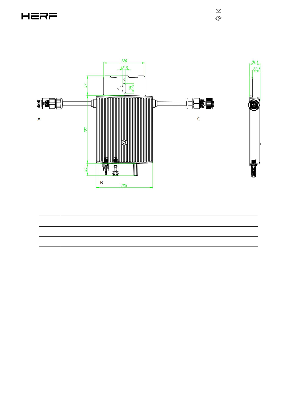
2.3Terminals Introduction
Object
Description
A
AC Connector (Male)
B
DC Connectors
C
AC Connector (Female)

202207V1.1
8
www.estarpower.com
3.About Function
3.1Work Mode
Normal: Under this mode, Microinverter is operating normally and convert DC power into AC power to support
the house loads and feed in to Public Grid.
Zero Export Control: Under this mode Microinverter’s generation is limit base on the current house loads, there
will be no extra power feed in to the Public Grid.
Stand by: There are several circumstances that Microinverter will stay in Standby mode:
The current condition is contradicted with Microinverter operating requirement.
No house loads or the Export control value has been set as “0” on the DCU under the Zero Export Control
mode.
202207V1.1
9
www.estarpower.com
4.About Installation
4.1Accessories
*Note: All accessories above are not included in the package, and need to be purchased separately.
Please contact our sales representative for the price. (M8 screws need to be prepared by
installer-self.)
Object
Description
A
AC End Cable (Male), 2m 12AWG Cable
B
DC Extension Cable, 1m
C
M8*25 screws
D
AC Female End Cap, IP68

202207V1.1
10
www.estarpower.com
4.2Installation Precaution
Please install the Microinverter and all DC connections under the PV module to avoiding direct sunlight,
rain exposure, snow layup, UV etc. Allow a minimum of 2 cm of space around the microinverter enclosure
to ensure ventilation and heat dissipation.
*Note: For some countries the DCU will be required to meet the local grid regulation (e.g., G98/99
for UK etc.)
4.3Space Distance Required
If the microinverters are installed on a concrete roof or steel roof, the communication with the DCU may
be slightly affected. Under such installation conditions, it is better for the microinverters to be installed
50cm above the roof. Otherwise, more DCUs may be required to ensure the communication quality
between the DCUs and the microinverters.
4.4Preparation
Installation of the equipment is carried out based on the system design and the place in which the
equipment is installed.
The installation must be carried out with the equipment disconnected from the grid (power disconnect
switch open) and with the photovoltaic modules shaded or isolated.
Referring to the Technical Data to make sure the environmental conditions fit the microinverter’s
requirement (degree of protection, temperature, humidity, altitude, etc.)
To avoid power de-rating due to an increase in the microinverter internal temperature, do not expose it to
direct sunlight.

202207V1.1
11
www.estarpower.com
To avoid overheating, always make sure the air flow around the inverter is not blocked.
Do not install in places where gasses or flammable substances may be present.
Avoid electromagnetic interference that can compromise the correct operation of electronic equipment.
When choosing the position of installation, comply with the following conditions:
Install only on structures specifically conceived for photovoltaic modules (supplied by installation
technicians).
Install Microinverter underneath of the photovoltaic modules to make sure it works in the shadow. If this
condition cannot be met, might trigger the inverter production de-rating.
4.5Installation Steps
4.5.1Step 1. Attach Microinverter on Rail.
A) Mark the approximate center of each panel on the frame.
B) Fix the screw on the rail.
C) Hang the microinverter on the screw (as shown in the picture below), and tighten the screw. The black
cover side of the microinverter should be facing the panel.

202207V1.1
12
www.estarpower.com
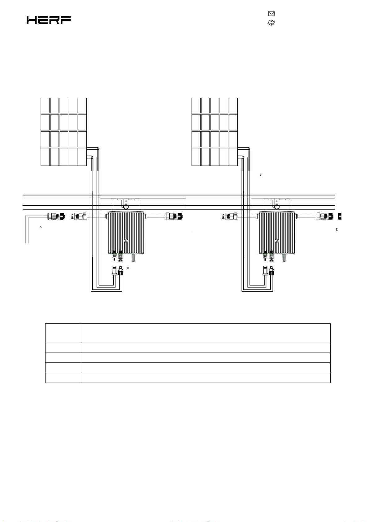
4.5.2Step 2. Connect AC Cables of Microinverter
A). Plug the AC connector of the first microinverter into the connector of the second microinverter
to form a continuous AC branch circuit.
B). Install the AC end cap on the open AC connector.
*Note: The length of AC cable on microinverter is roughly 2 m, if the distance between two
microinverters is more than 2m, please use an AC extension cable between two microinverters (as
shown in the picture below).
202207V1.1
13
www.estarpower.com
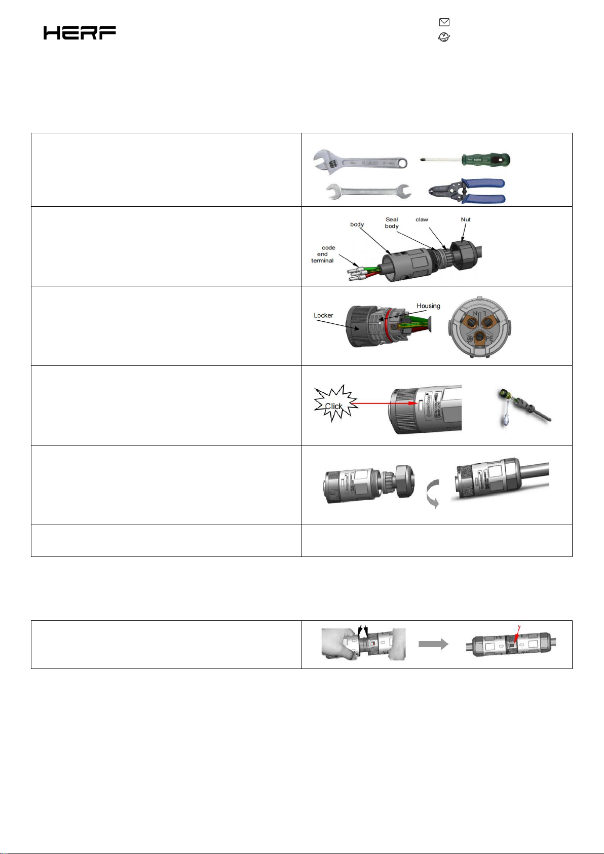
4.5.3Step 3. Connect AC End Cable
A) Installation of cable end connector.
Solid wrench No.30 or monkey wrench wide than 3cm 、
Cross screwdriver No.1、Wire striper.
a). Disassemble the connector and thread the cable through
the waterproof cap and connector housing
b).Connect the cable to the terminal, and the screw torque
is 0.8 + / - 0.1N ·m
c). Push Housing into Body
d). Insert Seal and Clamp Finger into body, then tighten the
nut, torque 2.5+/-0.5N·m
e). Installation of cable end male connector is the same as
female connector
Note: An electrical test should be done, to ensure that the connector has been installed correctly.
B) Connect the AC end cable with the AC branch circuit
a).Mating male and female connector: Push the plug into
the socket completely, then rotate the locker according to
the direction instructed by the marks on the locker
202207V1.1
14
www.estarpower.com
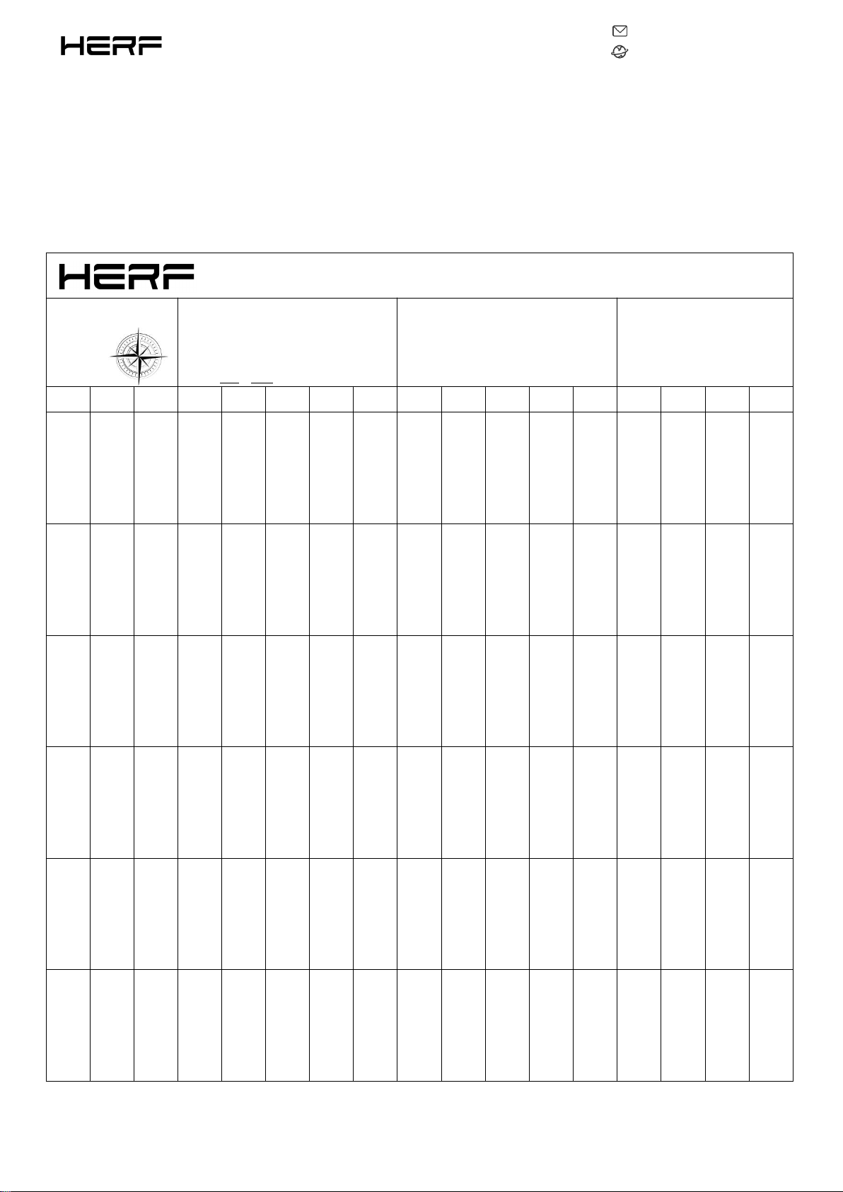
4.5.4Step 4. Create an Installation Map
Affix the serial number label to the respective location on the installation map.
Microinverter Installation Map V1.0
Please Make N for
North
Panel Type:
Azimuth:
Tilt:
Sheet of :
Customer Information:
DCU Serial Number:
1
2
3
4
5
6
7
8
9
10
1
12
13
14
15
16
A
B
C
D
E
F

202207V1.1
15
www.estarpower.com
4.5.5Step 5. Connect PV Modules
A) Mount the PV modules above the microinverter.
B) Connect the PV modules’ DC cables to the DC input side of the microinverter.

202207V1.1
16
www.estarpower.com
4.5.6Step 6. Energize the System
A) Turn on the AC breaker of the branch circuit.
B) Turn on the main AC breaker of the house. Your system will start to generate power after about two minutes
of waiting time.
4.5.7Step 7. Set Up the Monitoring System
Refer to the DCU User Manual or DCU Quick Installation Guide, and Quick Installation Guide for HERF
Monitoring Platform Online Registration to install the DCU and set up your monitoring system.

202207V1.1
17
www.estarpower.com
5. Troubleshooting
5.1Status LED Indicator
The LED flashes five times at start up. All green flashes (1s gap) indicate normal start up.
1.Start-up Process
Flashing green five times (0.3s gap): Start-up success
Flashing Red five times (0.3s gap): Start-up failure
2.Run Process
Flashing Fast Green (1s gap): Producing power.
Flashing Slow Green (2s gap): Producing power but one input is abnormal.
Flashing Red (0.5s gap): There is a fault that are not invalid AC grid or hardware failure, refer to HERF
Monitoring Platform for more details.
Flashing Red (1s gap): Not producing power due to invalid AC grid.
Solid Red: Hardware failure, refer to HERF Monitoring Platform for more details.
3.Other Status
Flashing Red and Green alternately: Firmware is corrupted.
*Note: All the faults are reported to the DCU, refer to the local APP of the DCU or HERF Monitoring
Platform for more information.
5.2On-site Inspection (For qualified installer only)
To troubleshoot an inoperable microinverter, follow the steps in the order shown.
1.Verify the utility voltage and frequency are within ranges shown in the in appendix Technical Data of this
microinverter.
2.Check the connection to the utility grid. Verify utility power is present at the inverter in question by removing
AC, then DC power. Never disconnect the DC wires while the microinverter is producing power. Re-connect the

202207V1.1
18
www.estarpower.com
DC module connectors and watch for five short LED flashes.
3.Check the AC branch circuit interconnection between all the microinverters. Verify each inverter is energized
by the utility grid as described in the previous step.
4.Make sure that any AC breaker are functioning properly and are closed.
5.Check the DC connections between the microinverter and the PV module.
6.Verify the PV module DC voltage is within the allowable range shown in appendix Technical Data of this
manual.
7.If the problem persists, please call HERF customer support.
*Note: Do not try to repair the microinverter. If the troubleshooting fails, please return it to the factory
for replacement.
5.3Routine Maintenance
1. Only authorized personnel are allowed to carry out the maintenance operations and are responsible to
report any anomalies.
2. Always use the personal protective equipment provided by the employer when carry out the maintenance
operation.
3. During normal operation, check that the environmental and logistic conditions are correct. Make sure that
the conditions have not changed over time and that the equipment is not exposed to adverse weather
conditions and has not been covered with foreign bodies.
4. DO NOT use the equipment if any problems are found, and restore the normal conditions after the fault
removed.
5. Conduct an annual inspection on various components, and clean the equipment with a vacuum cleaner or
special brushes.

202207V1.1
19
www.estarpower.com
6.Decommissions
6.1Decommissions
Disconnect the inverter from DC input and AC output; remove all connection cable from the Microinverter;
remove the Microinverter from the frame.
Please pack the Microinverter with the original packaging, or use the carton box that can afford 5kg weight
and can be fully closed if the original packaging is no longer available.
6.2Storage and Transportation
HERF packages and protects individual components using suitable means to make the transport and
subsequent handling easier. Transportation of the equipment, especially by road, must be carried out by
suitable ways for protecting the components (in particular, the electronic components) from violent, shocks,
humidity, vibration, etc. Please dispose the packaging elements in appropriate ways to avoid unforeseen
injury.
It is the customer’s responsibility to examine the condition of the components transported. Once receiving
the Microinverter, it is necessary to check the container for any external damage and verify receipt of all items.
Call the delivering carrier immediately if damage or shortage is detected. If inspection reveals damage to the
inverter, contact the supplier, or authorized distributor for a repair/return determination and instructions
regarding the process.
The microinverter storage temperature is -40-85℃.
6.3Disposal
If the equipment is not used immediately or is stored for long periods, check that it is correctly packed. The
This manual suits for next models
2
Table of contents
Other E Star Inverter manuals

Popular Inverter manuals by other brands


MGE UPS Systems
MGE UPS Systems 3.5 to 21 kVA N+1 owner's manual

Brainstorm Electronics
Brainstorm Electronics DXD-16 owner's manual

TOYODenki
TOYODenki VF66 EIP66-Z Communication Protocol Manual

Goobay
Goobay 67921 user manual
 TOWER KIT for WHISPER 500 owner's manual")
Southwest Windpower
Southwest Windpower 30 FOOT (9 Meter) TOWER KIT for WHISPER 500 owner's manual

Growatt
Growatt MIN 2500TL-X quick guide

Silicon Energy
Silicon Energy SiE2900 owner's manual

Gefen
Gefen GEFENTV-SIGGEN user manual

Goodwe
Goodwe GW73KLV-HT user manual

RBI
RBI UL 2703 installation guide

Jiangsu GoodWe Power Supply Technologu Co.
Jiangsu GoodWe Power Supply Technologu Co. SS series user manual

LG
LG N1T-L5 Series installation manual