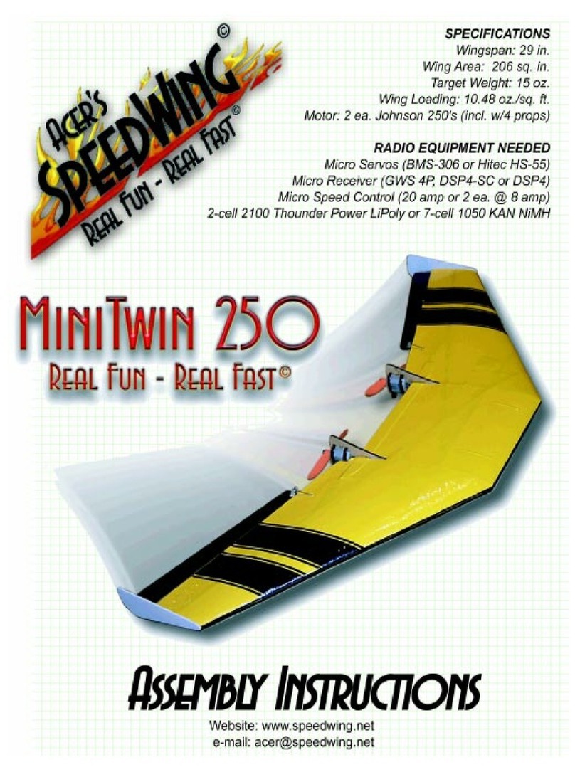
Aero Craft Kerswap Instruction Manual

Aero Craft Ltd.
Kerswap
Building Instructions
Wing Span: 51.8”
Wing Area: 400sq in
Fuselage Length: 33”
Flying Weight: 26-28oz
Motor Requirements: 100
W
Aero Craft Ltd.
432 Hallett Avenue Riverhead, NY 11901

Parts and materials included with the kit.
Bagged parts
4 - Magnets
1 – 3/16” .x 3” Dowel
2 – Flat landing gear straps
4 - #2 Sheet metal screws
1 – Hinge strip sheet
Strip bundle (36” Lengths)
10 - 1/8" sq. Balsa
2 - 1/8" x 1/4” Balsa
2 - 1/8" x 3/16" Balsa
2 - 1/4"sq. Balsa
1 - 3/16" x 3/8" Balsa
2 - 3/32" x 1/4" Balsa
4 - 1/8" x 1/4" Hardwood
Sheet balsa stock (36” Long)
4 - 3" x 1/16"
1 – 3/4” x 1/16”
Miscellaneous
2 – Formed wire landing gear
1 - .032” x 4” wire
Laser cut parts sheets
1 – Sheet#1 1/8” Balsa
1 – Sheet#2 1/8” Balsa
2 – Sheet#3 1/16” Balsa
2 – Sheet#4 1/16” Balsa
2 – Sheet#5 1/16” Balsa
1 – Sheet#6 1/16” Balsa
1 – Sheet#7 1/8 Lite Ply
1 – Sheet#8 1/16” Ply
1 – Sheet#9 3/16” Balsa
Page
1
of 31

Gilbert Morris Designer of the Kerswap
Gilbert Morris started building model airplanes at the age of 8 in 1933. He soon began building his own
designs. His main interest was in duration flying. His early efforts were all rubber powered. He bought his first
engine in 1939 and from that time on stayed with powered models. In the fall of 1941 Morris designed the
Kerswap. He built three Kerswaps that winter. During the 1942 contest season he lost all three models when
they flew out of sight!
Our version of the Kerswap was designed by Tom Hunt. The new version features a larger wing span, easier
to cover flat bottom airfoil, simplified construction and we have converted it for electric power. We think you will
enjoy this new edition of a fine old timer.
Tools and materials needed to build the Kerswap
A few simple tools and materials are needed to build the Kerswap. Experienced builders will probably already
have these items on hand. Beginning modelers should gather the items listed below before beginning
construction of this kit.
*Building board
We recommend purchasing a balsa wood building board. These boards are made of laminated
balsa to produce a flat work surface, an important requirement for building a straight airplane. They also accept
and hold pins very well. Other materials can make acceptable building boards. A piece of sheet rock or
plywood with one sanded surface may also be used. What ever material the modeler chooses for a building
board, remember it must be flat and should be at least 12” X 30” for the Kerswap.
*Sanding blocks
Using a sanding block will produce a better surface than hand held sandpaper. We make our
blocks by gluing sandpaper to a block of balsa wood. Commercially available sanding blocks can also be used.
A fine (about 220 grit) block and a medium (about 180 grit) block are needed. Some modelers finish sand their
models with a very fine grit paper such as 400. We don’t use paper that fine, the decision to do so is up to the
modeler.
*Glue
Several types of glue can be used. Aliphatic resin glues (carpenter’s cement) work fine but dry slowly.
Aliphatic resin’s slow drying time allows adjustment of the parts being assembled after the glue is applied.
Aliphatic resin glues have virtually no odor and allergic reactions are rare.
Cyanoacrylate adhesive (known to modelers as CA) offer nearly instant bonding. When using CA the parts are
first assembled, then a small drop of adhesive is applied to the joint. The adhesive will “wick” into the joint to
create the bond. Different viscosity CA is available. Thin CA requires a perfect joint between the parts being
assembled, the adhesive will not bridge any gaps. Thin CA works well for balsa to balsa joints but a good fit is
an absolute must. Medium CA is used in the same manner as thin but offers some gap bridging capability. Use
medium when gluing plywood or hardwood or if a small gap must be bridged. One thing to remember when
using CA...more is not better. Using too much adhesive will result in a weaker bond than using just enough to
do the job.
Page
2
of 31

There are a couple of disadvantages to CA. The adhesive bonds very well to skin. More than one modeler has
glued them self to their model. De-bonding chemicals are available, however most builders simply pull their
fingers away from the model leaving a bit of skin to be sanded off. Some people have an allergic reaction to
CA fumes. If the fumes irritate your sinuses consider using aliphatic resin to build the model.
*Pins
Any kind of pin will work. We like the kind made specifically for modeling because their large heads
make them easy to insert / remove and their sharp points eliminate wood splitting. Several dozen pins should
be on hand to hold parts to the building board and to each other during construction, especially if aliphatic resin
is used to build the model.
*Razor blades and hobby knife
We like single edge razor blades for general cutting of stock and when
covering the model with plastic film because they are sharper than hobby knife blades. A hobby knife may be
used and is best for certain jobs such as cutting hinge slots in flight surfaces. Remember to replace your razor
blade or hobby knife blade when they show signs of becoming dull.
*Ruler
There’s always something that needs measuring when building a model. If a metal rule is used it can
double as a straight edge when cutting stock or drawing location lines on parts.
*Wax Paper
Place a piece of wax paper over the plan when building a component directly on the plan. It will
prevent the component from being glued to the plan sheet. Plastic freezer wrap may also be used.
*Drill motor and bits
Holes must be drilled to mount the motor on the firewall and install other equipment. A
few small bits, 1/16” - 1/8” are all that is needed when building the Kerswap.
*Triangle
We like wooden building squares. They are good for squaring up parts during construction. The
edges of the triangle can also be used as a straight edge. Aero Craft Ltd. sells a kit with 4 building squares and
a rib aligning tool.
*Sealing iron
We suggest light weight plastic covering material when covering the model. These coverings
contain a heat activated adhesive for bonding to the structure. The material is then heat shrunk until tight.
*Velcro
Used to secure the battery and radio receiver in the model.
Accessories
As with all model airplane kits, some accessory items are needed to complete and fly the Kerswap. There are
two accessory categories, those items required to complete the airframe and those required to power and
control the finished model.
The accessory items recommended and used to build the model presented in these instructions are available
individually or as packages from Aero Craft Ltd. These items are listed below.
Items required to complete the airframe
*Dubro Micro push rod system – includes two push rod sets for rudder and elevator control.
*Pair 1-3/8” light weight wheels and wheel retainers.
*Covering material – Two rolls of material are required to cover the model if a single color scheme is chosen.
*Dubro micro control horns – these work well with the recommended push rod system and are easy to install.
*Small bottles of thin and medium viscosity CA or aliphatic resin
*2 Hour Epoxy
Items required to power and control the model
*100W outrunner type brushless motor
*9X4.7 slowflyer propeller
*15-20 amp motor controller
*Two micro servos
*Radio receiver
*Motor/receiver battery (2 cell 7.4V lipo pack)
The items listed here are those used on the various prototypes and are recommended. Similar items may be
substituted to suit builder preference.
Page
3
of 31

Construction
Construction begins by studying the plans, parts, and instructions. The builder should understand what is to be
done before committing glue to wood. This attitude towards building helps to eliminate mistakes and results in
a more enjoyable and successful building project.
Every model airplane kit should be built carefully. Good building practices will result in a better
looking and flying model. Taking the time to accurately cut stock and pre-fit parts pays off with an overall better
model. A few important points should be kept in mind throughout construction and are essential if the model is
to fly as designed.
*The model must be built true
...The fuselage must be straight, and the wing and tail surfaces cannot be twisted
or warped.
*The flight controls must operate smoothly with no binding.
*The model must be kept light
...There is no reason to “beef up” the Kerswap. Adding structure increases
weight and detracts from the models performance.
*The completed model must balance where shown on the plan
…An out of balance model will not fly properly
and could be dangerous.
Following the instructions carefully will help to insure these important requirements are accomplished.
Vertical Fin & Rudder
Parts and materials required for this building segment
Laser cut fin/rudder pieces V1, V2, V3, V4
3/16”x3/8” balsa strip stock
1) Cut the 3/16”x3/8” strip stock for the fin trailing edge
and the rudder leading edge and pin them over the
plan. Leave them long, they will be sanded to size
later. Cut a piece of 3/16”x3/8” strip stock for the
bottom of the rudder, trim the end to the correct angle,
and pin to the plan. Leave it a bit long as well.
Pin the fin trailing edge and
rudder leading edge to the
plan. Leave them long so
they can be trimmed later.
Line up the bottom piece for the
rudder over the plan and cut the
end to the correct angle. Pin it
to the plan.
2) Use rudder trailing edge V4 lined up over the plan to
mark the end of the 3/16”x3/8” strip stock to be used
for the rudder center piece. Cut it and pin it and part V4
to the plan.
Use part V4 to mark the center
piece for the rudder. Cut it to
shape.
Pin the rudder center
section and part V4 to
the plan.
Page
4
of 31

3) Pin parts V2 and V3 over the plan. Use fin leading edge V1 lined up over the plan to mark the end of the
3/16”x3/8” strip stock to be used for the fin center piece. Cut it and pin it and part V1 to the plan.
Pin parts V2 and V3
over the plan.
Use part V1 to mark
the center piece for the
fin. Cut it to shape.
Pin the fin center
section and part V1 to
the plan.
4) Glue the fin and rudder parts together, be careful not to glue
the fin trailing edge and rudder leading edge to each other.
Remove the fin and rudder from the plan.
Glue the fin and rudder parts together.
(Don't glue the fin to the rudder!)
5) Sand the extra lengths of 3/16”x3/8” flush with the rudder and fin, Keep the shape as shown on the plan.
Round the leading edge of the fin and rudder.
Sand the ends of the 3/16”x3/8”
stock that were left long.
Round off the leading edge of
the fin.
Round off the leading
edge of the rudder.
6.) Mark the location of the hinges on the fin and rudder. Using a piece
of 3/32” balsa as a spacer, cut the slots for the hinges.
Cut the slots for the hinges in
the fin and rudder.
Page
5
of 31

Stabilizer & Elevator
Parts and materials required for this building segment
2 ea of laser cut pieces S1, S1A, S1B, S2, S2A, S3, S3A, S4, S4A, S5, S6, S7, S8, S9, SP1, and SP2
1/8”x1/4” balsa strip stock
3/32”x1/4” balsa strip stock
NOTE: Be careful, the 1/8”x1/4” and 3/32”x1/4” balsa strip stock are very close in size.
1) Pin both the stabilizer trailing edge
S8, and the elevator leading edge S8
over the plan.
Pin both S8's over the plan.
2) Cut the 1/8”x1/4” stock for the elevator upper spar
a bit long and cut the lower spar to length.
Cut the upper spar stock a bit
long to allow for it's curve and
some overlap.
Cut the lower spar to the
length shown on the plan.
3) Using the stabilizer ribs placed
against the trailing edge as guides,
pin the lower spar to the plan. Pin
both parts S7 over the plan.
Using the ribs as a guide pin the lower spar to the
plan..
Pin both S7's onto the
plan.
Page
6
of 31

4) Check the placement of the stabilizer ribs then pin the top spar in place. Set the spacing of the S1 ribs using
the vertical fin. Pins parts SP1 and SP2 onto the plan with the vertical fin in place.
Check that the stabilizer ribs
are in place and vertical.
Use the vertical fin to place
the S1 ribs.
Pin parts SP1 and SP2 to
plan with the vertical fin in
place.
5) Sight along a building square or triangle
to make sure the fin is vertical. Glue the S1
ribs and parts SP1 and SP2 in place.
Remove the vertical fin.
Make sure the fin is vertical.
Glue ribs S1 and parts SP1 and
SP2 in place.
6) Place the S1B ribs in place on top of SP1 and SP2 and glue in place. Glue in the rest of the ribs, parts S7
and the upper and lower spars.
Glue the S1B ribs on top
of SP1 and SP2.
Glue the rest of the ribs
and both spars in place.
Glue both S7 parts in place.
Page
7
of 31

7) Cut 2 pieces of 3/32”x1/4” balsa strip stock for the leading edge about an inch or so longer than needed.
Soak them in warm water for a few minutes until they are soft and pliable. Place them on the plan and pin them
in place with T-Pins. Start in the middle and work towards the outside. Pull in the rear piece first then the front
one. Place a couple of pins on the inside of the leading edge between S5 and S7 and also outside of S7 to
help the balsa stay fitted to the curve. Let dry throughly, then glue in place. If using a
liphatic resin, glue the rear
piece first, then glue the front piece to it. The modeler may continue with the next steps while the leading edge
is drying.
Soak the 3/32”x1/4” balsa
leading edge in warm water,
then pin the softened pieces in
place over the plan.
Use extra pins near the ends to
help the balsa hold the correct
shape. Let the balsa dry before
gluing in place
8) Put elevator trailing edge part S6 on the plan but don't pin it into place yet. Put ribs S4A, S3A, and S2A into
place over the plan. Use the ribs to set the proper position for the trailing edge and then pin it into place. Sand
a bevel onto the wide end of rib S1A so it sits flush against S8. Trim the short end of S1A so it sits flush against
S6. While holding S1A in place pin S9 in place against it.
Using the elevator ribs to line it
up in part S6 on the plan.
After sanding S1A to sit
flush against S8 trim the
end to sit flush against S6
While holding S1A in
place pin S9 in place
against it.
9) Make sure the elevator ribs are vertical and in the correct position then
glue the assembly together.
10) Repeat steps 8 and 9 for the other side of the elevator.
Glue the assembly together.
Page
8
of 31

11) If the stabilizer leading edge pieces
have not yet been glued, make sure they
are completely dried and glue them to the
front of the stabilizer and each other.
Glue the stabilizer leading edge
to the ribs.
Glue the pieces of the stabilizer
leading edge together.
1
2) Remove the stabilizer and elevator from the plan.
Trim and sand the ends of stabilizer leading and
trailing edges to shape. Trim and sand the ends of the
elevator leading edge to shape.
Trim then sand the
stabilizer leading edge
to shape.
Trim then sand the
elevator leading edge to
shape.
13) Pin or tack glue the stabilizer and elevator together and sand the curve around the joint. Sand the tops of
the S8's even with the ribs and sand the S6 parts to follow the line of the ribs.
Pin the stabilizer and
elevator together then sand
the curve where they join.
Sand the S8 parts even
with the ribs.
Sand the S6 parts to
follow the line of the ribs.
Don't sand it too thin.
14) Mark then cut 1/16” sheet balsa to fit
between S1B and S1 forward of the
stabilizer spar. Glue in place.
Mark then cut 1/16” sheeting to
fit between S1B and S1.
Glue the 1/16” sheeting place.
Page
9
of 31

15) Mark then cut 1/16” sheet balsa to fit between the S1B ribs behind the spar. Mark and cut a slot for the fin,
then glue the sheeting in place.
Mark then cut 1/16” sheeting to fit
between the S1B ribs.
Mark then cut a slot in the
sheeting for the fin.
Glue the finished sheeting
in place.
16) Sand the leading edge of the
stabilizer even with the ribs and round it
according to the plan. Sand a bevel onto
the leading edge of the elevator as
shown on the plan.
Sand the leading edge of the
stabilizer round as per the plan.
Bevel the stabilizer trailing and
elevator leading edges.
Pylon
Parts and materials required for this building segment
Laser cut platform parts WP1, WP2, WP3
Laser cut pylon parts P1, P2, P3, P4, P5, P6, 2 ea P7
3/16” dowel
1) Pin platform parts WP1, WP2, and WP3
over the plan. Make sure that they fit
together tightly. Glue them to each other
and then remove the wing platform from
the plan.
Pin the platform sections to the plan.
Make sure the pieces fit tightly.
Glue the platform sections together.
2) Build the pylon core by pining
the pylon parts P1, P2, P3, P4, P5,
and P6 onto the plan. Make sure
the parts fit tightly and that the top
and bottom edges line up. Glue the
parts together and then remove the
core from the board.
Pin the pylon pieces to the plan. Insure they fit
snugly and the top and bottom are even.
Glue the pylon sections to each other.
Page 10
of 31

In order to have enough time to complete the next step use a slow setting epoxy. We recommend at least 30
minute. NOTE: Do not use aliphatic resin for this step, as it will cause the pieces to warp.
3)Cut the two pieces of 3/16” dowel used for the wing hold downs to the length shown on the plan. Place one
of the pylon sides P7 onto the plan, coat it with a thin layer of slow setting epoxy. Take the assembled pylon
core and coat both sides of it with a thin layer of epoxy. Place the core on top of P7. Put the dowel pieces into
place in the slots in the core. Add some epoxy to fill in the rest of the holes around the dowels. Take the other
P7 and put a thin coat of epoxy on it before placing it over the core. Weight down the assembly after making
sure the pieces line up. Allow the epoxy to cure completely before removing the weights. Once the epoxy has
cured, remove the pylon from the board and clean up any excess epoxy around the edges.
Mark and cut the dowel
pieces for the wing hold
downs.
Spread out a thin layer of
epoxy on all the pieces to be
joined.
Check that the upper and lower
edges of the P7 pieces and the core
are even.
4) Pin the wing platform down on the board. Glue
the pylon to the platform making sure it is fully
seated into the slots in the platform and
perpendicular to it. Be careful to have the platform
facing the right way. We recommend using epoxy
for this joint. When the epoxy has fully cured
round the leading and trailing edges of the pylon.
Make sure the pylon is kept
perpendicular to the wing
platform.
Round the pylon's leading and
trailing edges.
Page 11
of 31

Fuselage
Note: The stabilizer must be done before the fuselage so the modeler can fit the cover pieces by the fin.
Fuselage side preparation - Parts and materials required for this building segment
2ea – Laser cut fuselage side pieces F1 & F2
1/8”x1/8” strip stock
1/8”x1/4” hardwood stock
1) Start with the right hand side. Pin one set of fuselage sides F1 & F2 over the side view on the plan. Line
them up carefully and make sure the joint between the panels is tight.
Make sure the side pieces are centered over the plan side view.
2) Mark the locations of the formers,
1/8”sq sticks, and the location of the
forward 1/8”x1/4” landing gear support on
the fuselage sides using a ruler lined up
with the hash marks on the plan.
Make sure to draw the line for the
landing gear support using the
rear landing gear leg shown on
the plan.
Draw lines to locate the formers and
1/8"sq sticks on the fuselage sides.
3) Pin 1/8”sq strip stock to the top of side. Align the stock with the front
of the side and leave the rear end long, it will be trimmed later.
Use a square to help align the strip
stock the the edge of the fuselage side.
Page 12
of 31

4) Pin 1/8”sq strip stock to the bottom of side.
Align the stock with the front of the side and leave
the rear end long, it will be trimmed later. Be sure
to leave a gap at the
rear
landing gear leg.
Be sure to leave a gap for the
landing gear at the rear leg for the
right hand side.
Leave the ends long, they will
be trimmed later.
5) Glue the 1/8”sq strip stock to the fuselage
side, also glue the seam between the halves.
Glue the strip stock to the fuselage
side.
Don't forget to glue the seam
between the halves.
6) Remove the fuselage side from the plan
and trim the ends of the 1/8”sq stock at the
rear.
Trim the ends of the 1/8"sq strip
stock even with the fuselage sides.
Support the fuselage side as the pins
are removed.
7) Measure and cut the 1/8”sq strip stock pieces for
the fuselage sides. Measure and cut the 1/8”x1/4”
hardwood landing gear supports.
Carefully mark then cut the 1/8"
strip stock pieces to fit.
Use the 1/8"x1/4" hardwood
stock for the landing gear
supports.
Page 13
of 31

8) Glue the 1/8”sq pieces and the forward landing gear
support onto the fuselage side. Glue the rear landing gear
support onto the fuselage side using the landing gear leg
to insure the correct spacing.
Use a landing gear leg to
get the correct spacing
between the landing gear
support blocks.
Make sure the 1/8"sq
pieces are aligned with
the marks.
9) Now do the left hand side. Pin the second set of fuselage sides over the side view on the plan. (See step 1)
Line them up carefully and make sure the joint between the panels is tight. Glue the halves together.
10) Mark the locations of the formers, 1/8”sq sticks, and the location of the
forward 1/8”x1/4” landing gear support on the side of the fuselage side using a
ruler and the hash marks on the plan.
Make a mark on the fuse aligned
with the hash marks on the plan.
11) Remove the fuselage side from the plan and turn it over. Draw lines for the
locations of the formers, 1/8”sq sticks, and the location of the forward 1/8”x1/4”
landing gear support on the fuselage side using a ruler and the marks on the
sides made earlier.
Mark the fuselage side using the
tick marks made earlier.
12) Pin 1/8”sq strip stock to the top of side. Align the stock with the front of the side and leave the rear end
long, it will be trimmed later.(See step 3)
13) Pin 1/8”sq strip stock to the bottom of side. Align the stock with the front
of the side and leave the rear end long, it will be trimmed later. Be sure to
leave a gap at the front landing gear leg. (See step 4)
Line up the right and left hand sides as show in the picture to make sure the
gap for the landing gear leg is in the right place. The right hand side is on
top.
Use the right hand side to check
that the gap is in the right place.
Page 14
of 31

14) Glue the 1/8”sq strip stock to the fuselage side. (See step 5)
15) Remove the pins from the fuselage side and trim the ends of the 1/8”sq strip stock at the rear of the
fuselage. (See step 6)
16) Measure and cut the 1/8”sq strip stock pieces for the fuselage sides. Measure and cut the 1/8”x1/4”
hardwood landing gear supports. (See step 7)
17) Glue the 1/8”sq strip stock pieces and the forward landing gear support onto the fuselage side. Glue the
rear landing gear support onto the fuselage side. The modeler can use the landing gear leg to insure the
correct spacing. (See step 8)
Fuselage assembly - Parts and materials required for this building segment
Assembled fuselage side pieces from previous step
LG1, F5, 2 ea PS1 – Laser cut balsa parts
LG2, LG3, FW – Laser cut lite ply parts
F1, F2, F3, F4 – laser cut ply parts
1/8”x1/8” strip stock
1) Pin the right hand fuselage side right side up over the bottom view on
the plan. Use a building square to make sure the side is vertical. Only
pin up to former F3.
Pin the right hand side over the
bottom view lining it up as shown.
2) Measure and cut the 1/8”sq strip stock pieces to go across the bottom of the fuselage forward of former F3.
Pin these into place over the plan.
Cut the 1/8" sq. pieces for
the fuselage bottom
Pin the 1/8" sq pieces over the plan. (Only those in front of former F3)
3) Glue formers F2 and F3 in place against the fuselage
side. Make sure they are vertical and square to the
fuselage side. Keep the fuselage side vertical while gluing
in the formers.
Glue formers F2 and F3 to the fuselage
side, keeping everything square.
Page 15
of 31

4) Pin the right hand fuselage side over the plan, fitting
formers F2 and F3 into the side. Glue F2 and F3 to the
left hand fuselage side. Glue the 1/8”sq pieces on the
bottom to both fuselage sides.
Glue the left hand fuselage
side onto formers F2 and F3
Glue the 1/8”sq pieces in
between the fuselage sides.
5) Put F1 in place on the front of the fuselage, carefully lining it up
even with the front end of the fuselage sides. Make sure the opening
for the wires is on the bottom so they will not interfere with the battery
hatch. Glue F1 to the fuselage.
Make sure F1 is aligned even with the front
of the fuselage.
6) Glue part LG1 in place between the fuselage sides. Make sure LG1
is tight against F1.
Make sure that LG1 is flush with the
front of the fuselage.
7) While holding the fuselage sides together, place former F4 between
them. Line it up over the plan, making sure it is vertical and centered
over the middle of the fuselage plan view. Glue former F4 in place
between the fuselage sides.
Glue former F4 into place making
sure it's centered and vertical.
Page 16
of 31

8) Remove the pins holding the fuselage to
the board. Trim the ends of lower stringers as
shown on the plan. Glue part F5 in between
the ends of the fuselage sides, butted up
against former F4.
Trim the ends of the fuselage sides as
per the plan.
Glue F5 up against former F4
9) Measure and cut the 1/8” strip stock pieces for
the top and bottom of the fuselage between
formers F3 and F4. Glue the sticks in place while
keeping the fuselage square and straight.
Measure and cut the 1/8"sq
sticks for the fuselage top.
Glue the 1/8"sq pieces onto the top
of the fuselage.
10) Glue part PS1 into the bottom of the
fuselage above the stringers, butted up
against former F2. Glue another PS1
into the top of the fuselage below the
stringers, butted up against F2.
Glue part PS1 above bottom stringers
against former F2
Glue part PS1 below top stringers
against former F2
11) Place the fuselage upside down on the building
board and glue part LG2 onto the bottom of the
fuselage centered over part LG1 and even with the
front of the fuselage. Place part FW up against the
front of the fuselage to help line up LG1, but don't
glue FW at this time. Place part LG3 on the bottom
of the fuselage. The modeler can insert the landing
gear legs into the fuselage and use them to line up
LG3. Glue LG3 onto the bottom of the fuselage
over LG1.
Glue part LG2 onto the bottom of
the fuselage, even with the front.
Glue part LG3 onto the
fuselage bottom, using the
landing gear for spacing.
Page 17
of 31

12) Turn the fuselage right side up and glue part FW onto the front of the
fuselage. Make sure that the holes in FW are aligned with the holes in F1
and that the fuselage is sitting flat on the LG2 and LG3 parts.
Glue part FW onto the front of the
fuselage, making sure it's even with
LG2.
Battery and radio hatch assemblies - Parts and materials required for this building segment
Assembled fuselage from previous step
H1, H2, 2 ea HM – Laser cut balsa parts
3”x1/16” balsa sheet
4ea small magnets
1) Take two of the small magnets and stick them to each other. Make a mark on the exposed side of each
magnet. These marks will be used to insure that the magnets are facing the right way when installed. Glue one
of the magnets into the hole in part HM, with the marked side flush with the surface of the part. Glue part HM
into the front of the fuselage, below the 1/8”sq stringers, with the marked side of the magnet facing up. Leave a
small gap between it and former F1 as shown on the plan.
Mark the outside of both
magnets while they are
stuck together.
Glue the marked side of the
magnet flush with the surface of
HM.
Glue HM to the underside of
the stringers. Leave a small
gap between it and F1.
2) Glue the other magnet into the hole in the part H1, with the mark
facing the inside side of the hatch. Leave a small gap between the
magnet and the inside surface of the hatch to prevent the two magnets
from touching each other when the hatch is installed. If they touch, a lot
of force will be needed to open the hatch.
Glue the other magnet into H1
with the mark on the bottom,
leave a small gap between the
magnet and surface of H1.
Page 18
of 31

3) Mark then cut a piece of 3”x1/16” sheet stock a bit longer the fuselage is wide and glue it to part H1 with the
grain going across H1. Line it up even with the end of H1 that has the magnet in it. Be sure to glue it over the
unmarked
side of the magnet and centered on H1. Add another cross grain piece next to the first piece leaving
about 1/4” of H1 exposed, as shown on the plan. (The exposed edge will fit under the fuselage sheeting
holding the hatch in place.) Put the battery hatch in place on the fuselage and check the fit. Sand the edges of
the hatch even with the fuselage sides
Glue 1/16" cross grain sheeting
along H1 on the side opposite
the mark on the magnet.
Sheet the rest of H1 leaving about
1/4" exposed as per the plan.
Sand the sheeting on H1 even with
the fuselage sides.
4) Repeat steps 1 to 3 for the radio hatch using part H2. For the radio hatch
part HM is glued into the fuselage above the 1/8”sq stringers butted against
former F2.
Glue the second HM above the
bottom stringers against F2,
marked magnet side facing out.
Top Sheeting - Parts and materials required for this building segment
3”x1/16” balsa sheet
1) Put cross grain 1/16” sheeting on the top of the fuselage starting with a
small piece in front of the battery hatch. Cut the piece from the 3”x1/16”
sheet stock to be slightly wider than the fuselage. Be sure to put a small
gap in front of the battery hatch to leave room for covering. Once the
sheeting is in place sand the sides to match the fuselage.
Put a small piece of cross grain
sheeting in front of the battery hatch.
Leave a gap for the covering.
Page 19
of 31
Table of contents
