Acer SpeedWing MiniTwin 250 User manual


MiniTwin 250MiniTwin 250
MiniTwin 250
®
- by Acer
ASSEMBLY INSTRUCTIONS
Thank you for choosing the MiniTwin 250 as your next project. This kit is easy to build and
only requires a few hours to complete. Once finished, you will be rewarded with a stable,
FAST, fun to fly wing that you can take anywhere. It is the perfect “take to work” plane to fly
on those lunch breaks or to stop by the park on the way home. Although this kit isn’t
recommended for beginners because of its high speed and agility, once you master the basics
of flying R/C planes you can handle this plane. Well lets get started. Below is a list of supplies
and tools needed to complete the MiniTwin 250.
Supplies
• Velcro Tape (for battery attachment)
• Dubro Micro EZ-Connects (for servo horns)
• Pen
• 5 minute epoxy
• 320 grit sand paper (or equivalent)
• Hobby knife
• Dremel Tool (optional)
• Thin CA (superglue)
• CA Accelerator (optional)
• Two sided foam tape (for servo anchor)
• 3M #600 3/4" tape (for hinges)
• Covering tape or Low Heat iron on covering
• 3M 77 Spray Adhesive
• 1" wide fiberglass strapping tape (found at Home Depot)
Radio Equipment
• Micro receiver (GWS 4P , Berg 4 DSP)
• Micro Servos - 2 ( HS-55 recommended)
• Small Speed Control (20 amp) or 2,7-10 amp speed controls for Rudder Operation
• 7-cell NiMh Battery (KAN 1050) or 2, 2-cell 1200-2100 LiPoly batteries or 2-cell 2100
Thunder Power LiPoly
• V-tail mixer (optional for Rudder operation if you don’t have a mixing Computer Radio)
2

Instructions
1. Separate cores from their beds. Use the extra piece of EPP to lightly rub off the hairs left
over from the foam cutting process, you may need to use your fingers to pick off heavier hairs.
2. Find the ply motor mount. The laser cutting
process leaves the edges darker than the wood, if you
want to you can lightly sand the edges.
3. If you are using an ASTRO 010 or equivalent,
leave the motor mount as it is and cut out the two
motor tie wrap holes towards the back of the mount. If
you are using the stock motor, cut out the spacer in the
motor mount and the motor tie wrap holes closest to
the front of the mount.
4. Using 5 minute epoxy, glue the motor mounts to
the center core. Make sure that the mounts are
aligned to the shape of the wing core and that the two
cutouts at the back are on both top and bottom of the
wing.
4a. Once that is dry, epoxy the left and right wing
cores to the assembly. Before the epoxy dries, make
sure that the wing cores line up. Wait for the epoxy to
dry. Lightly sand the leading edge so that it is rounded.
5. Mark the areas where you will recess your radio
gear. You can put the gear where ever you like, but
here is the recommended location. The servos are
placed on top of the wing 3 ½ inches behind the nose
and 1.5 inches to the left and right of the center ply
mount. The servo wires are put through the wing and
into the ESC hole. The receiver and ESC location is on
the bottom of the wing. Also mark where you will route
the wires . If you are using the 2-cell 1200 LiPoly
batteries, place your radio gear as far forward as
possible so that you can retain the C.G. without adding
weigh (
Refer to pictures below
). 3

Note: ESC #2 is if you want Rudder operation (
details later
). OR you can use a V-Tail mixer if
you don’t have a mixing computer radio (
See Diagrams on page 10
).
6. Once everything is marked out,
take a sharp hobby knife and cut
around the outlines you just made
(
only cut as deep as the part you are
going to recess
). Once that is
finished take a Dremel tool or
other means to remove just
enough foam for your radio gear to
sit flush with the surface of the
wing. Temporarily mount all radio
gear to make sure everything fits
snug. Once you are sure of the fit,
remove gear. Mix a little 5 minute
epoxy and paint it in the servo
holes. This helps the servo tape
to stick.
7. Lightly mist the whole wing with 3M 77 spray. Let the wing dry for about 20 minutes.
8. Now permanently install the radio gear making sure that your servos are centered and that
the servos move in the right direction for elevon operation. To do this make sure the left
aileron makes the left elevon move up and the right elevon move down, right aileron makes
the right elevon move up and the left elevon move down, up elevator makes both elevons
move up and down elevator makes both elevons move down. Also make sure your rudder
works the way it should, details below. Take the Xacto and slice a shallow line in the wing
from the receiver to the tip of the wing. Bury the antenna in the slice using your nail. Just
work slowly as it is a little tedious. Leave the excess antenna dangle at the tip of the wing for
now.
9. You will have to cut a small
piece of EPP away from the back
of the motor mount so that your
motor can fit into the mount. Use
your motor as a guide to cut a
small piece at a time until your
motor fits snugly between the EPP
when inserted fully into the mount.
4

Installing the Carbon Fiber Reinforcement
To install the carbon fiber tape, you’ll need some paper masking tape, thin CA, a plastic
sandwich bag or wrap, your wing beds, some type of weights , a pair of small scissors and a
hobby knife. We would recommend you read this portion of the instructions over fully before
attempting this procedure. Remember that all CA products will bond instantly with skin (as
they were designed to do) and it is always best to understand completely what you intend to
do the CA before you start!
1. First, we are going to install the carbon fiber on the bottom of the wing. Take your upper
wing beds and place them on an elevated surface (use a few short pieces of 2x4’s or
something to hold the beds about 1-1/2” or more off the table, yet fully supporting the beds).
Now set your wing into the beds upside down. If the top of the motor-mount hits the tabletop,
you will have to elevate the beds somewhat higher. When setting the top of the wings into the
beds, you will notice that the servo control arms hit slightly into the foam of the beds. Just
press them in a little with your thumb on top of the servo areas on the wing, then lift out the
wing and set it aside for a moment. Using a hobby knife, look into the beds for 2 small
impressions where the control arms hit and cut out around those indentations slightly and
shallowly. Return the wings into the beds, making sure they seat fully, if not cut some more
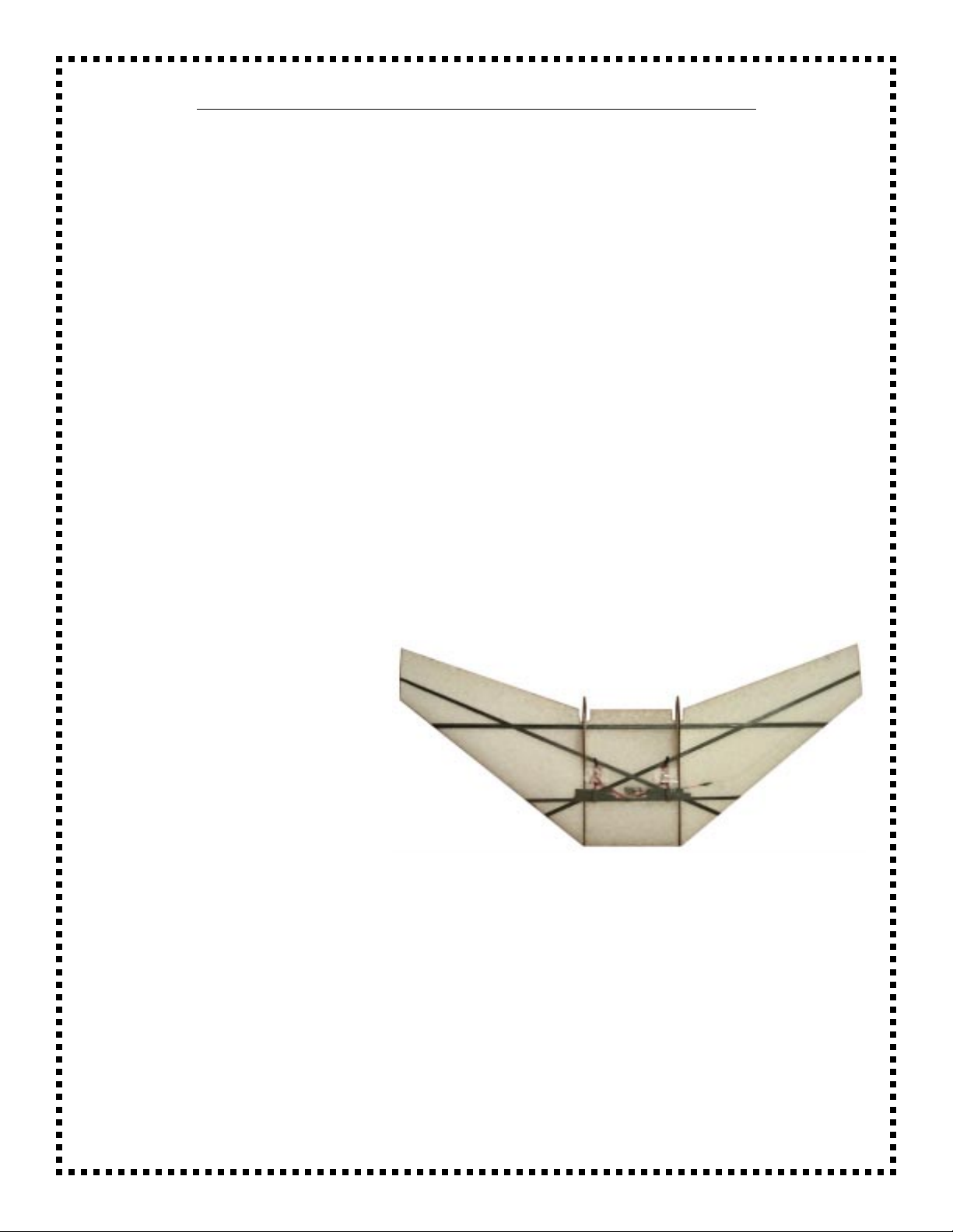
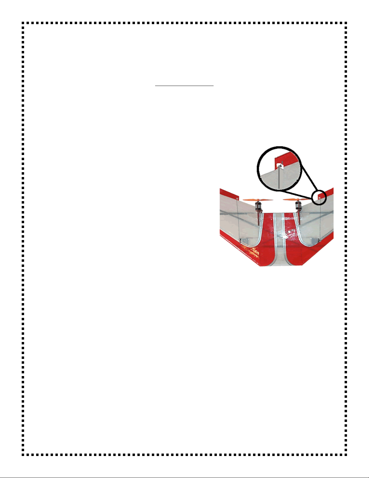
1a. Place one of the lengths of carbon fiber tape through one of the holes in the rear portion of
the mount. Leaving about 1” overlap past the wing on both ends, cut the CF tape to length -
MAKING SURE TO LEAVE THE 1” OVERLAP AT BOTH ENDS! Using some masking tape,
secure one side of the CF tape
down tightly to one side of the core
-- NOT ONTO THE WING
ITSELF! Stretch the other end of
the CF tape tightly, then mask
down this other end to the other
core side as well. Using this same
process, apply the two remaining
lengths of CF tape to this side of
the wing -- just as you see
illustrated here. We can’t
emphasize enough how important
it is to keep the CF tape stretch very taught and mask very tightly down to the beds. Done
right, this is by far the strongest and lightest method available to reinforce an EPP foam wing,
Done wrong... Well you know the rest.
1b. After all the CF tape has been placed and masked down securely, put some small weights
on the top of the wing, making sure to miss placing them on the CF tape. Look over your work
carefully at this point making sure that the wing set perfectly flat on the table in fully down into
the beds. Now wrap your finger in a double layer of plastic sandwich bag or wrap (to keep the
CA off of you) and working on one line of CF tape at a time, squeeze out some thin CA on top
of one of the CF tapes while using your plastic wrapped finger to rub it in and spread it out.
You may notice some heating as the Carbon and the CA chemically react, but keep rubbing
as long as you comfortably can. Using this same procedure, complete the thin CA application
5

to all of the remaining CF tape on this side of the wing.
1c. Remove the masking tape and trim off the excess CF tape. It is best to do this on a bias
parallel to the front of the wing and at about halfway point to the wing thickness. Just trim
flush to the wing tips for the
remainder of the CF tape.
Remove the weights and wing
from the wing beds. This
completes application of the CF
tape to this side of the wing.
2. Now use the exact same
process to install the carbon tape
on the upper surface of the wing
using the other set of wing beds to
secure the wing into, just as
illustrated here.
3. Use the 1" strapping tape and
tape down the leading edge. This
is used to keep the L.E. from
being ripped or cut when hitting
wires, poles, etc..
4. Now find the two ply wing
joiners and glue them in the slots
in the motor mounts with 5 minute
epoxy.
5. Now use a sharp xacto and cut
the excess foam out from behind
the wing joiner on the center core.
Covering the Wing
You can cover the wing any way you want. If you are going to use iron on covering, make sure
to use LOW HEAT covering material (Econokote, Solite). For simplicity, I prefer to use colored
packing tape like that used on other wings. I’ll give you instructions on how to use the tape for
covering.
1. First take the color of tape that will be on the top of the wing. Run a strip of the colored
tape along the trailing edge making sure that equal amounts are on the top and bottom of the
wing.
(Note: this is a picture of a similar wing, the same method applies)
2. Cover the top of the wing first. Only cover half at a time making sure to overlap the center
of the wing by about 2 inches. Start from the trailing edge and work your way to the leading
edge. Make sure that you have a very sharp Xacto handy while covering. Also make sure that
6

you don’t introduce a warp in the
wing.
3. Once the top is covered, cover
the bottom in the same way,
preferably with a contrasting color
of tape. Once again working your
way from trailing edge to the
leading edge. You can take the
warp out that you may have
introduced with the top covering by
stretching the bottom tape before
applying.
4. Now use a strip of the bottom
covering and overlap the top
covering at the leading edge.
5. Find the elevons in your kit.
The elevons are precut, but you
have to sand in the bevel on the
bottom of the elevon. Also sand
an angle at the front of the elevon
for clearance.
6. Lightly spray the elevon with 77 spray and let dry (if you are using iron on covering, don’t
spray). Cover the elevon with the colored tape you used for the bottom of the wing.
7. Now attach the elevons to the
top of the wing using 3M 600 3/4"
tape. Bend the elevons to their
maximum deflection before taping
to the wing. Also put a couple of
small strips of tape (2") on the
bottom of the elevon making sure
to deflect the elevon before taping
to the wing.
8. Use the included templet to cut out the tiplets from the coroplast included in your kit. Use
an xacto to make a small hole in the side of one tiplet and run your antenna through the hole
and into the flutes. Pull the excess antenna through the tiplet. Attach the tiplets to the wing
7

8
using a small amount of 5 minute epoxy, leaving about 1" extending under wing.
9. Now run the excess antenna back and forth through the flutes in the tiplet, leaving a couple
inches extending out the back of the tiplet.
Final Setup
1. Find the micro control horns and install them in the top of the elevons. Just push them
through making sure that they are lined up with the control horns of the servos. Cut the
covering away from where the micro control horns sit. Now permanently attach the horns with
thin CA. Once that is dry, you can cut off the post sticking through the elevon.
2. Make a small “Z” bend in the end of both music
wire pushrods. Attach the pushrods to the elevons.
Make sure that your servos are centered, then cut the
pushrods to the correct length. If you are using the
Dubro micro EZ-Connects, all you have to do is slide
the pushrods through the EZ-Connect and tighten the
screw making sure that the elevon has a very slight
reflex (up angle) to the wing. If you are not using the
EZ-Connects, mark the location of the servo arm on
the pushrod and make another z-bend. Then insert
the z-bend into the control horn of the servo. I
recommend the Dubro EZ-Connects as it makes for a
MUCH simpler setup.
3. The battery is attached using Velcro. I suggest the use of Industrial strength Velcro as it is
much stronger. First lightly “paint” some 5-minute epoxy in the battery bay (you can thin the
epoxy by using denatured alcohol) and let dry. Then position the battery where you can obtain
the correct C.G. This is where you will install the velcro. If you are using a single battery and 2
speed controls, you will have to make a “Y” connector, if you use two smaller LiPoly batteries
you can connect them normally.
4. Attach the motor to the motor mount using the tie wraps included. Make sure that you
tighten the tie wraps fully. Attach the prop to the motor making sure that the letters on the
prop are facing forward. Make sure that the rubber adapter doesn’t rub on the motor. If you
are using 2 ESC’s, plug the motors into their speed controls. If you are only using 1 ESC (no
rudder), snip the connectors off of each motor and solder the red motor wires to the red ESC
wire, then the black motor wires to the black ESC wire. Be sure to cover the solder joints with
heat shrink or electrical tape.

Control Throws
Here are the recommended control throws. If you have a radio with exponential, I recommend
at least -70% exponential on all surfaces. Start on the mild setting. When measuring control
throws, measure at the tip of the elevon at its widest point.
Mild Wild
Elevator: 1/4" up, 1/4" down Elevator: 3/8" up, 3/8" down
Aileron: 1/4" up, 1/4" down Elevator: 3/8" up, 3/8" down
Center of Gravity
The center of gravity is located 4 3/4" back from the nose. Just move the battery back and
forth until you find the right C.G. (You may have to add a slight amount of weight to the nose if
you use 2, 2-cell 1200 ETEC LiPolys
First Flight
Make sure that your control surfaces move in the right directions. When you give up both
elevons should go up. When you give right, the right elevon goes up and the left elevon goes
down. You will need to have a slight amount of UP elevator dialed in. This is called reflex. All
wings need a certain amount of reflex to fly. Make sure the rubber prop adapter doesn’t touch
the motor. To launch the wing grasp the back of the wing in the center and toss, then start the
motor after it leaves your hand. There is no need to give it full throttle as it will fly at 1/4
throttle. Trim it for level flight. LIGHTLY oil the motor at both bushings after every 2 hours or
so of flight. This will extend the motor life.
Flight Performance
The Mini Twin 250 has a very wide flight envelope. It can fly as fast as 70 m.p.h. or it can slow
down and just cruise around. It is very acrobatic also, able to do consecutive loops and about
6 barrel rolls per second with the “wild” control throws. It has unlimited vertical using 2s2p
1200 ETECS. It can even thermal pretty well. Yet it will still slow down for an easy hand
catch. If you set up the rudder control, you will be able to do many maneuvers like hammer
head stalls. It is also able to do a type of flat spin that is exclusive to this wing. I hope you
enjoy your new Mini Twin 250.
Thanks again for your purchase. We appreciate it!

Optional Rudder Operation (differential thrust)
You can have rudder control by mixing the signal to two ESC’s either by using your
Computer radio mixes, or by using an onboard V-Tail mixer. This gives you differential
thrust in both motors that you can control with your rudder stick and acts much like a
normal rudder. It also can make your wing do EXTREMELY fast flat spins. Here are
the two ways you can make the rudder work. Important: You will have to take out the
positive (
red
) lead on one of the ESC’s where it plugs into the receiver. This is so that
you don’t put too much power into the receiver. Either tape the contact or apply some
heath shrink to insulate it from touching other components.
Computer Mixing: For computer mixing you have to go into the programming
mode on your computer and use Premix 1 and Premix 2. Here’s how they are set.
Mixes Master Slave Settings
Premix 1 Premix 2 Channel 3 Channel 4
Channel 4 Channel 3 +100 U, +100 D -100 L, -100 R
V-Tail Mixing: If you don’t
have a computer radio, you
can use a simple V-Tail mixer
to create differential thrust.
The GWS V-Tail mixer
available on our website
works well with this setup.
Simply plug your RIGHT
speed control into the TOP
plug of the mixer and your
LEFT speed control into the
BOTTOM plug of the mixer.
Now plug the lead marked
AILERON into Channel 4 in
your receiver and the lead
marked ELEVATOR into
Channel 3 in your receiver.
You now have differential
thrust.
Before going to the next step, temporarily insert the motors into the motor
mounts and plug the motors into the speed controls. Now plug in your battery
and make sure the differential thrust is working.
10
Table of contents
Popular Toy manuals by other brands

Tower Hobbies
Tower Hobbies P-51 MUSTANG MKII EP Rx-R instruction manual

Eduard
Eduard Ju 87D quick start guide

WowWee
WowWee RoboMe instruction manual

Fisher-Price
Fisher-Price Pixter Color ARCADE B8005 owner's manual

Freewing
Freewing A-10 Thunderbolt II user manual

Extreme Flight
Extreme Flight 91" Yak-54 ARF Assembly manual

WATT AGE
WATT AGE Mini-Max EP instructions

Billing Boats
Billing Boats Norden instructions

Hasbro
Hasbro Spiderman 3 Venom Mask and Wrist Blaster... instruction manual

marklin
marklin BR 218 user guide

Eduard
Eduard Su-30 Flanker G interior S.A. manual

Modeltech
Modeltech MUSTANG P-51D .46 ARF Instructions for final assembly