AeroComm ConnexLink User manual

ConnexLink
ConnexLinkConnexLink
ConnexLink
User’s Manual
User’s ManualUser’s Manual
User’s Manual
Version 1.2
Version 1.2Version 1.2
Version 1.2
10981 EICHER DRIVE
10981 EICHER DRIVE10981 EICHER DRIVE
10981 EICHER DRIVE
LENEXA, KS 66219
LENEXA, KS 66219LENEXA, KS 66219
LENEXA, KS 66219
(800) 492-2320
(800) 492-2320(800) 492-2320
(800) 492-2320
www.aerocomm.com
www.aerocomm.comwww.aerocomm.com
www.aerocomm.com
sdycus@aerocomm.com
sdycus@aerocomm.comsdycus@aerocomm.com
sdycus@aerocomm.com

Document Information
Document InformationDocument Information
Document Information
7/11/2003 2
Copyright
CopyrightCopyright
Copyright
Information
InformationInformation
Information Copyright © 2001 AEROCOMM, Inc. All rights reserved.
The information contained in this manual and the accompanying
software programs are copyrighted and all rights are reserved by
AEROCOMM, Inc. AEROCOMM, Inc. reserves the right to make
periodic modifications of this product without obligation to notify
any person or entity of such revision. Copying, duplicating, selling, or otherwise
distributing any part of this product without the prior consent of an authorized
representative of AEROCOMM, Inc. is prohibited.
All brands and product names in this publication are registered
trademarks or trademarks of their respective holders.
This material is preliminary
This material is preliminaryThis material is preliminary
This material is preliminary
Information furnished by AEROCOMM in this specification is believed to be accurate. Devices sold
by AEROCOMM are covered by the warranty and patent indemnification provisions appearing in its
Terms of Sale only. AEROCOMM makes no warranty, express, statutory, and implied or by
description, regarding the information set forth herein. AEROCOMM reserves the right to change
specifications at any time and without notice.
AEROCOMM’s products are intended for use in normal commercial applications. Applications
requiring extended temperature range or unusual environmental requirements such as military,
medical life-support or life-sustaining equipment are specifically not recommended without
additional testing for such application.
Limited Warranty
Limited WarrantyLimited Warranty
Limited Warranty
For a period of one (1) year from the date of purchase, AEROCOMM warrants the transceiver
against defects in materials and workmanship. AEROCOMM will not honor this warranty (and this
warranty will be automatically void) if there has been any:
(1) Tampering, signs of tampering, or opening the tranceiver’s case.
(2) Use of AC power adapters and cables other than those originally supplied with the
transceivers.
(3) Repair or attempt to repair by anyone other than an AEROCOMM authorized
technician.
This warranty does not cover and AEROCOMM will not be liable for, any damage or failure caused
by misuse, abuse, acts of God, accidents, electrical irregularity, or other causes beyond
AEROCOMM's control, or claim by other than the original purchaser.

FCC Information
FCC InformationFCC Information
FCC Information
7/11/2003 3
FCC Notice
FCC NoticeFCC Notice
FCC Notice
RF Exposure (For 200mW units only: Part Numbers CL200 & CL200A)
RF Exposure (For 200mW units only: Part Numbers CL200 & CL200A)RF Exposure (For 200mW units only: Part Numbers CL200 & CL200A)
RF Exposure (For 200mW units only: Part Numbers CL200 & CL200A)
WARNING:
WARNING:WARNING:
WARNING: This device complies with Part 15 of the FCC Rules. Operation is subject to
the following two conditions: (1) This device may not cause harmful
interference and (2) This device must accept any interference received,
including interference that may cause undesired operation.
WARNING:
WARNING:WARNING:
WARNING: To satisfy FCC RF exposure requirements for mobile and base station
transmitting devices, a separation distance of 32cm or more should be
maintained between the antenna of this device and persons during
operation. To ensure compliance, operations at closer than this distance is
not recommended.
The preceding statement must be included as a CAUTION statement in
manuals for OEM products to alert users on FCC RF Exposure compliance.

Table of Contents
Table of ContentsTable of Contents
Table of Contents
7/11/2003 4
USER’S MANUAL............................................................................................................1
FIGURES...........................................................................................................................4
TABLES.............................................................................................................................4
1. OVERVIEW..............................................................................................................5
1.1 CONNEXLINK DEFINITIONS......................................................................................6
1.2 CABLE PINOUT DEFINITIONS....................................................................................7
1.3 CONNEXLINK CONFIGURATION UTILITY SOFTWARE ...............................................7
1.3.1 Installation ......................................................................................................7
1.3.2 Software Definitions........................................................................................8
1.3.3 Programming ................................................................................................10
2. API COMMAND SET............................................................................................12
2.1 SYSTEM COMMAND SET.........................................................................................13
2.1.1 Reset..............................................................................................................13
2.1.2 Control ..........................................................................................................14
2.1.3 Diagnostic Result ..........................................................................................14
2.1.4 Standby..........................................................................................................15
2.1.5 Status Request ...............................................................................................15
2.1.6 Status Reply...................................................................................................15
2.1.7 Update EEPROM Checksum.........................................................................16
2.1.8 Check EEPROM Checksum ..........................................................................16
2.1.9 EEPROM Checksum Status...........................................................................16
2.1.10 Acknowledge..................................................................................................17
2.2 CONNEXLINK COMMAND SET................................................................................17
2.2.1 RF Enable......................................................................................................17
2.2.2 Send Data......................................................................................................18
2.2.3 Send Data Complete......................................................................................18
2.2.4 Received Data ...............................................................................................19
2.2.5 In Range ........................................................................................................19
2.2.6 Out of Range..................................................................................................19
3. TROUBLESHOOTING .........................................................................................20
Figures
FiguresFigures
Figures
Figure 1 - Multiple Networks Of ConnexLink Units.....................................................5
Figure 2 - ConnexLink Bottom View..............................................................................6
Tables
TablesTables
Tables
Table 1 - System Command Set..................................................................................13
Table 2 - ConnexLink Command Set..........................................................................17
ConnexLink User’s Manual
ConnexLink User’s ManualConnexLink User’s Manual
ConnexLink User’s Manual
7/11/2003 5
1.
1.1.
1. Overview
OverviewOverview
Overview
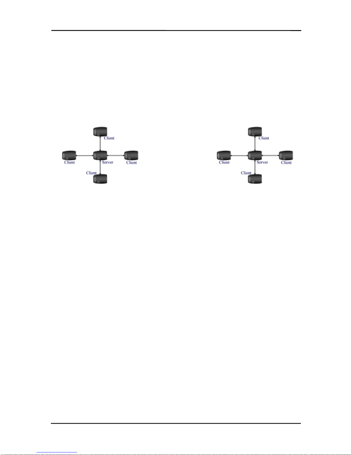
The ConnexLink products provide a wireless RS232 connection between different devices. Each
ConnexLink unit can be programmed as a Server or a Client, allowing for the creation of a two
device or multiple device wireless network. In addition, multiple networks can be created by
programming each network of ConnexLink units with unique Channel Number and System ID
combinations. See Figure 1 below.
See Figure 1 below.See Figure 1 below.
See Figure 1 below. To create a wireless network, simply program one of the
units as a Server and the other units as Clients.
Figure
FigureFigure
Figure 1
11
1 - Multiple Networks Of ConnexLink Units
- Multiple Networks Of ConnexLink Units- Multiple Networks Of ConnexLink Units
- Multiple Networks Of ConnexLink Units
Example: Channel Number = 13
S
y
stem ID = 001002003004005006007008 Example: Channel Number = 25
S
y
stem ID = 012023034045056067078089

ConnexLink User’s Manual
ConnexLink User’s ManualConnexLink User’s Manual
ConnexLink User’s Manual
7/11/2003 6
1.1
1.11.1
1.1
ConnexLink Definitions
ConnexLink DefinitionsConnexLink Definitions
ConnexLink Definitions
1. Pwr
PwrPwr
Pwr: Red LED indicates power is connected to the unit.
2. Link
LinkLink
Link: Green LED indicates the Client unit(s) and Server unit are in range of one another.
Link LED remains activated on Server units. Client units activate the Link LED when in
range of the Server unit
3. Rx
RxRx
Rx: Red LED indicates when a ConnexLink unit is receiving data.
4. Tx
TxTx
Tx: Green LED indicates when a ConnexLink unit is sending data.
5. Reset Button
Reset ButtonReset Button
Reset Button: Push-button switch located closest to the power connector and serial
cable on the bottom of the unit. See Figure 2
Figure 2Figure 2
Figure 2 below.
6. Program Button
Program ButtonProgram Button
Program Button: Push-button switch located next to the Reset Button
Reset ButtonReset Button
Reset Button on the bottom of
the unit. See Figure 2
Figure 2Figure 2
Figure 2 below.
Figure
FigureFigure
Figure 2
22
2 - ConnexLink Bottom View
- ConnexLink Bottom View- ConnexLink Bottom View
- ConnexLink Bottom View
ConnexLink User’s Manual
ConnexLink User’s ManualConnexLink User’s Manual
ConnexLink User’s Manual
7/11/2003 7
1.2
1.21.2
1.2
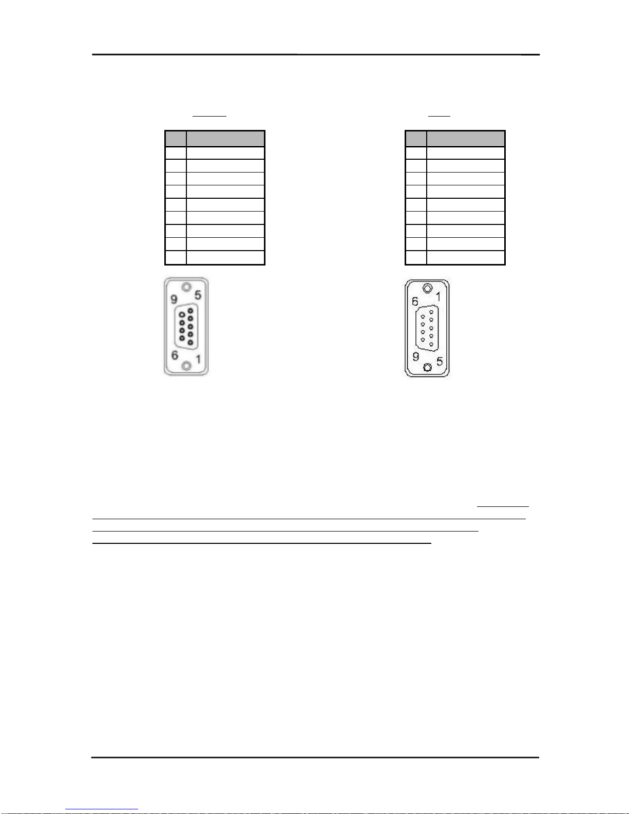
Cable Pinout Definitions
Cable Pinout DefinitionsCable Pinout Definitions
Cable Pinout Definitions
Standard RS232 DB9
Standard RS232 DB9Standard RS232 DB9
Standard RS232 DB9 Female
FemaleFemale
Female Connector
ConnectorConnector
Connector Null Modem
Null ModemNull Modem
Null Modem RS232 DB9
RS232 DB9RS232 DB9
RS232 DB9 Male
MaleMale
Male Connector
ConnectorConnector
Connector
1.3
1.31.3
1.3
ConnexLink Configuration Utility Software
ConnexLink Configuration Utility SoftwareConnexLink Configuration Utility Software
ConnexLink Configuration Utility Software
The software CD included with your ConnexLink units provides a utility for changing the settings
on each unit. The software is compatible with Microsoft® Windows 95, 98, 2000, Me, NT and XP.
1.3.1
1.3.11.3.1
1.3.1 Installation
InstallationInstallation
Installation
Follow the procedure below to install the ConnexLink Configuration Utility software. There are 2
software versions to choose from depending on whether or not the ConnexLinks have Program
Buttons. To determine the correct version of software, inspect the bottom side of the
ConnexLinks to see if Program and Reset are occupied with push buttons.
1. Insert the CD into the desired CD-ROM drive on your computer.
2. Click on the Windows Start
StartStart
Start menu and select Run
RunRun
Run.
3. Select Browse
BrowseBrowse
Browse and then select the appropriate CD-ROM drive letter.
4. Select the file named Setup.exe
Setup.exeSetup.exe
Setup.exe and then select Open
OpenOpen
Open.
5. Select OK
OKOK
OK to begin the installation.
6. When prompted, accept the default directory or change to the desired directory where
the program files will be installed.
7. Select Installation
InstallationInstallation
Installation to begin copying files.
8. When finished, a window will be displayed indicating a successful installation. Select
OK
OKOK
OK.
Pin Description
1DCD
2RxD
3TxD
4DTR
5GND
6DSR
7RTS
8CTS
9RI
Pin Description
NC DCD
2TxD
3RxD
4DSR
5GND
6DTR
7CTS
8RTS
NC RI

ConnexLink User’s Manual
ConnexLink User’s ManualConnexLink User’s Manual
ConnexLink User’s Manual
7/11/2003 8
1.3.2
1.3.21.3.2
1.3.2 Software Definitions
Software DefinitionsSoftware Definitions
Software Definitions
1. C
CC
Client/Server
lient/Serverlient/Server
lient/Server: Designates ConnexLink type. In each network, there must be only one
Server. All other ConnexLink units must be programmed as Clients. The number of
Clients in the network is not limited; however, if performance diminishes, consider
additional RF Networks.
2. B
BB
Baud Rate
aud Rateaud Rate
aud Rate: This defines the serial baud rate between the ConnexLink unit and the host
device, such as a PC. The RF transmission rate is fixed. Default baud rate setting is
57600 unless the units have been pre-configured by AeroComm.
3. Maximum
MaximumMaximum
Maximum T
TT
Transmit Attempts
ransmit Attemptsransmit Attempts
ransmit Attempts: For Point-to-Point networks only. This value represents
the maximum number of times a data packet can be sent by the ConnexLink units. The
default value is 16 attempts. If communication is lost and the Client’s Link
LinkLink
Link LED is on, try
increasing this value in small increments until communication is reestablished. The valid
range of values for this field is 1 to 255.
4. B
BB
Broadcast Attempts
roadcast Attemptsroadcast Attempts
roadcast Attempts: For Point-to-Multipoint networks only. This value represents the
number of times a data packet will be sent by the Server ConnexLink unit. The default
value is 4 attempts. If communication is lost and the Clients’ Link
LinkLink
Link LED is on, try
increasing this value in small increments until communication is reestablished. The valid
range of values for this field is 1 to 255.
5. Channel Number
Channel NumberChannel Number
Channel Number: A number that designates an independent network of ConnexLink
units. Up to 77 independent networks can created. The valid range of values for this
field is 0 to 76.

ConnexLink User’s Manual
ConnexLink User’s ManualConnexLink User’s Manual
ConnexLink User’s Manual
7/11/2003 9
6. Packet Length
Packet LengthPacket Length
Packet Length: Defines the fixed length or size of data packet to be transmitted. Any
packets larger than the Packet Length will be parsed and sent consecutively by a
ConnexLink. For example, if the Packet Length is 128 bytes and the Host sends 150
bytes, a ConnexLink will send 128 bytes and then 22 bytes after the Interface Timeout
expires. Any packets smaller than the Packet Length will be transmitted once the
Interface Timeout has expired.
The Host can send variable-sized data packets, all of which are equal to or smaller than
the Packet Length. A ConnexLink will wait until the Interface Timeout expires or until the
Packet Length size is reached. Therefore, if multiple packets and/or portions of packets
are sent before the Interface Timeout expires, the receiving ConnexLink Host must be
able to process the multiple packets and/or portions of packets.
Packets will be transmitted over the RF interface when one of the following conditions
occurs: 1) The number of data bytes received over the serial interface is equal to the
Packet Length or; 2) A byte gap larger than the Interface Timeout occurs. The maximum
packet size is 07FFh or 2KB. This can be set to 00h, 40h, 80h, or C0h designating 4ms,
40ms, 300ms, and 2.6s timeouts, respectively.
7. Interface Timeout
Interface TimeoutInterface Timeout
Interface Timeout: This parameter specifies the amount of time between bytes that a
ConnexLink will wait before transmitting the data packet.
8. System Identification
System IdentificationSystem Identification
System Identification: A sequence of eight numbers that provide added security to each
independent network of ConnexLink units. The System ID is used in conjunction with the
Channel Number and serves as a password to maintain secure transfers of data. The
combination of the Channel Number and System ID must be unique to each network of
ConnexLinks to establish communication. Here are some examples:
Network A: Channel Number – 13, System ID – 001 002 003 004 005 006 007 008
Network B: Channel Number – 25, System ID – 012 023 034 045 056 067 078 089
Multiple Servers in the same coverage area must be programmed with different Channel
Numbers to prevent inoperability of the networks. The System ID will not prevent
inoperability that occurs from locating multiple Servers with the same Channel Number in
the same coverage area. The valid range of values for each of the eight numbers is 0 to
255.
Important Note
Important NoteImportant Note
Important Note: For a network of ConnexLink units to communicate with each
: For a network of ConnexLink units to communicate with each: For a network of ConnexLink units to communicate with each
: For a network of ConnexLink units to communicate with each
other, all ConnexLink units
other, all ConnexLink unitsother, all ConnexLink units
other, all ConnexLink units must
mustmust
must have identical Channel Numbers and System
have identical Channel Numbers and Systemhave identical Channel Numbers and System
have identical Channel Numbers and System
IDs. If additional networks are created, each network must use different Channel
IDs. If additional networks are created, each network must use different ChannelIDs. If additional networks are created, each network must use different Channel
IDs. If additional networks are created, each network must use different Channel
Numbers and System IDs so that existing networks are not interfered with.
Numbers and System IDs so that existing networks are not interfered with.Numbers and System IDs so that existing networks are not interfered with.
Numbers and System IDs so that existing networks are not interfered with.
9. API Mode
API ModeAPI Mode
API Mode: Allows the Server Host to address specific Clients via AeroComm’s API
Command Set. The commands include the MAC address of the specific Client. See
Section 2 for the API Command Set.
10. Transparent Mode
Transparent ModeTransparent Mode
Transparent Mode: Configures both Client and Server to transmit and serial data sent by
the Host.
11. Mix Mode
Mix ModeMix Mode
Mix Mode: Allows a Client to transmit its MAC address to a Server in API Mode.
12. Parity
ParityParity
Parity: Enables the ConnexLink to transmit and even or odd parity bit. All ConnexLinks
in the network must have Parity enabled for accurate communication. The Link LED will
be deactivated when Parity is enabled.
13. RTS
RTSRTS
RTS: Enables the Request to Send control line.
ConnexLink User’s Manual
ConnexLink User’s ManualConnexLink User’s Manual
ConnexLink User’s Manual
7/11/2003 10
14. Modem Control
Modem ControlModem Control
Modem Control: Enables DCD, DTR, DSR and Ring Indicator control lines.
15. Firmware Version
Firmware VersionFirmware Version
Firmware Version: Displays the ConnexLink’s firmware version.
16. MAC Address
MAC AddressMAC Address
MAC Address: A unique 6 Byte, IEEE 802.3 Ethernet address assigned by AeroComm to
each ConnexLink. The user must not changethis information.
1.3.2.1
1.3.2.11.3.2.1
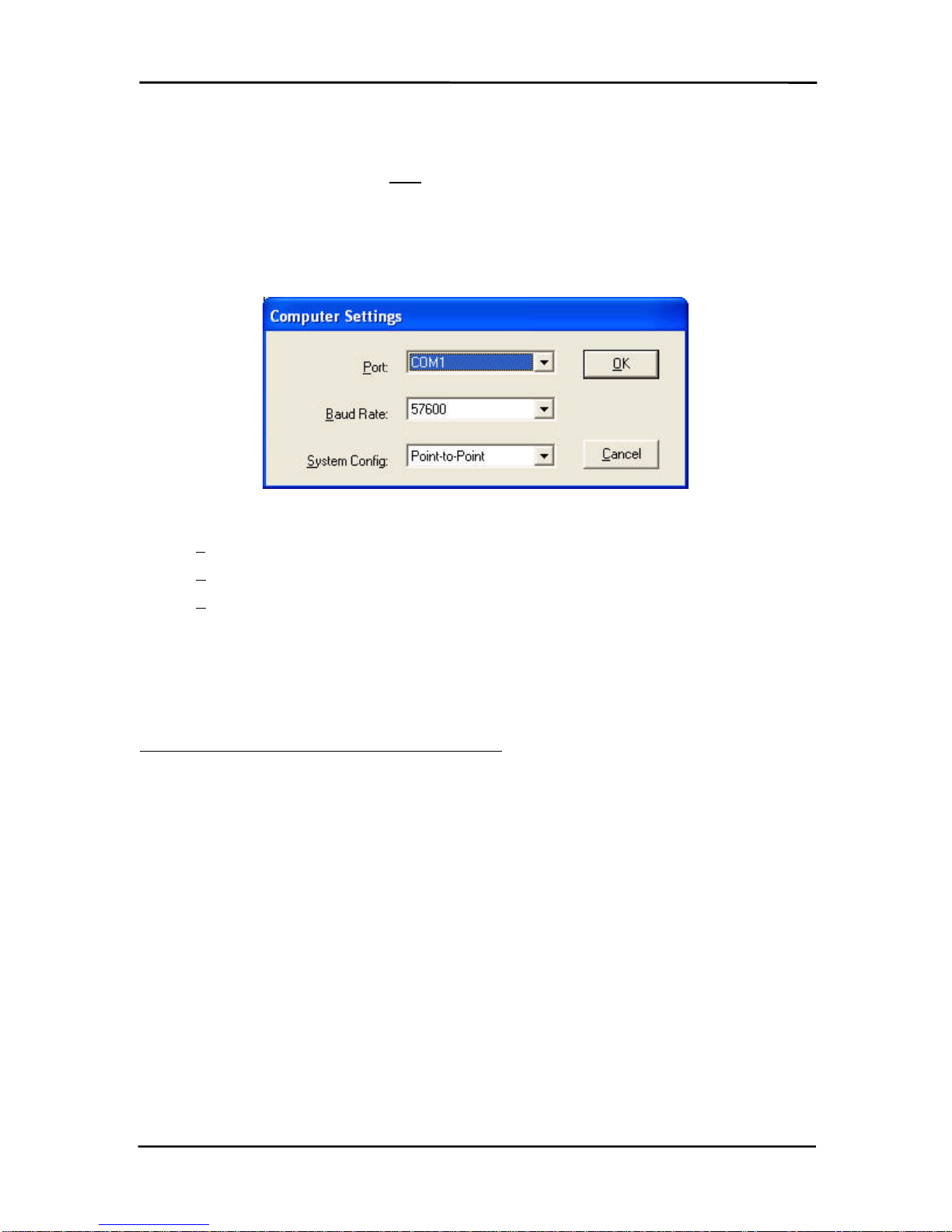
1.3.2.1 Computer Settings Window
Computer Settings WindowComputer Settings Window
Computer Settings Window
1. P
PP
Port
ortort
ort: Serial communications port connected to the ConnexLink unit.
2. B
BB
Baud Rate
aud Rateaud Rate
aud Rate: Serial baud rate of the PC COM Port.
3. S
SS
System Config
ystem Configystem Config
ystem Config: Type of ConnexLink network to be configured. Valid choices are Point-
Point-Point-
Point-
to-Point
to-Pointto-Point
to-Point (one Server and one Client) or Point-to-Multipoint
Point-to-MultipointPoint-to-Multipoint
Point-to-Multipoint (one Server and multiple
Clients).
1.3.3
1.3.31.3.3
1.3.3 Programming
ProgrammingProgramming
Programming
Each ConnexLink unit must be set up in Program Mode before any settings can be changed.
Units without Program Buttons do not require Step 5. This is accomplished with the following
procedure:
1. Connect a ConnexLink unit to a serial communications port on your computer.
2. Connect the power supply to the ConnexLink unit. Make sure the Pwr
PwrPwr
Pwr LED is on.
3. Start the ConnexLink Configuration Utility.
4. Select Settings
SettingsSettings
Settings to display the Computer Settings window.
a. Select the COM Port that is connected to the ConnexLink unit.
b. Select the baud rate of the ConnexLink unit. All ConnexLink units are shipped
with a default baud rate of 57600. If the baud rate of the ConnexLink unit is
changed as described below in Section 1.2.3.1 Changing ConnexLink Settings
Section 1.2.3.1 Changing ConnexLink SettingsSection 1.2.3.1 Changing ConnexLink Settings
Section 1.2.3.1 Changing ConnexLink Settings,
then this setting must be set to the same baud rate to allow proper programming
of the units.
c. Select the system configuration for the ConnexLink network, Point-to-Point
Point-to-PointPoint-to-Point
Point-to-Point (one
Server and one Client) or Point-to-Multipoint
Point-to-MultipointPoint-to-Multipoint
Point-to-Multipoint (one Server and multiple Clients).
d. Select OK
OKOK
OK.

ConnexLink User’s Manual
ConnexLink User’s ManualConnexLink User’s Manual
ConnexLink User’s Manual
7/11/2003 11
5. Press and hold the Program Button
Program ButtonProgram Button
Program Button located on the bottom the unit. While holding the
Program Button
Program ButtonProgram Button
Program Button, press the Reset Button
Reset ButtonReset Button
Reset Button also located on the bottom of the unit. Release
the Reset Button
Reset ButtonReset Button
Reset Button first, followed by releasing the Program Button
Program ButtonProgram Button
Program Button. An alternative method
for putting the ConnexLink in Program Mode can be done by pressing and holding the
Program Button, cycling power to the unit, then releasing the Program Button. The
ConnexLink unit is now in Program Mode. See Figure 2. ConnexLink Bottom View
Figure 2. ConnexLink Bottom ViewFigure 2. ConnexLink Bottom View
Figure 2. ConnexLink Bottom View for
location of buttons.
1.3.3.1
1.3.3.11.3.3.1
1.3.3.1 Changing ConnexLink Settings
Changing ConnexLink SettingsChanging ConnexLink Settings
Changing ConnexLink Settings
After the ConnexLink unit has been set up in Program Mode, any settings can be changed and
saved in the unit. This is accomplished with the following procedure:
1. Select Read Radio
Read RadioRead Radio
Read Radio to display the current settings of the ConnexLink unit.
2. Change desired settings.
3. After all changes have been made, select Write Radio
Write RadioWrite Radio
Write Radio to save the changes. Disregard
Steps a through d if the ConnexLinks do not have Program Buttons.
a. A message window will be displayed – Press and hold the Program Button
Program ButtonProgram Button
Program Button.
b. While holding the Program Button
Program ButtonProgram Button
Program Button, select OK
OKOK
OK.
c. Wait for a message window to be displayed, confirming the saved changes.
d. Release the Program Button
Program ButtonProgram Button
Program Button and select OK
OKOK
OK.
4. Cycle Power to the unit after all changes have been saved. This will set the ConnexLink
unit to its normal mode of operation.

ConnexLink User’s Manual
ConnexLink User’s ManualConnexLink User’s Manual
ConnexLink User’s Manual
7/11/2003 12
2.
2.2.
2. API Command Set
API Command SetAPI Command Set
API Command Set
In API Mode, the Host and ConnexLink utilize a set of commands to program the EEPROM
parameters defined in Section 6, Configuring the AC5124C
Section 6, Configuring the AC5124CSection 6, Configuring the AC5124C
Section 6, Configuring the AC5124C, as well as control and monitor
network communications. As mentioned in Section 4.3, Serial Interface Mode 03 – API
Section 4.3, Serial Interface Mode 03 – APISection 4.3, Serial Interface Mode 03 – API
Section 4.3, Serial Interface Mode 03 – API, the
commands are grouped into two categories, System Commands and ConnexLink Commands.
Each group of commands are listed and defined in this section. It is important to note these
commands can only be used when a ConnexLink is operating in the API Mode, which is
accomplished by programming bits 0 and 1 of EEPROM address 4Ah to a value of 1. The
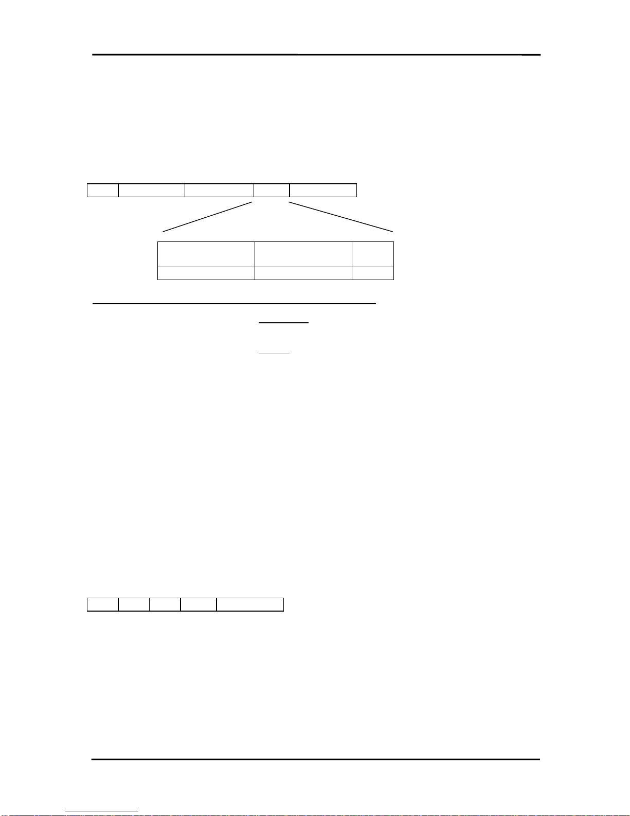
command format is defined as follows:
Command Length Data Checksum
Command
CommandCommand
Command (1 Byte) – Hex command as shown in Table 1 – System Command Set
Table 1 – System Command SetTable 1 – System Command Set
Table 1 – System Command Set and
Table 2 – ConnexLink Command Set
Table 2 – ConnexLink Command SetTable 2 – ConnexLink Command Set
Table 2 – ConnexLink Command Set.
Length
LengthLength
Length (2 Bytes) – This is the total size of the remaining data for this command. The
length field is in little endian format (i.e. low byte/high byte). This length does not include
the checksum.
Data
DataData
Data (N Bytes) – The actual data associated with the command or sub-command.
Checksum
ChecksumChecksum
Checksum (1 Byte) – The checksum is a byte-by-byte, bitwise “EXCLUSIVE OR” of the
Command, Length and Data block.
Here are some important facts to remember when operating in API Mode:
Here are some important facts to remember when operating in API Mode:Here are some important facts to remember when operating in API Mode:
Here are some important facts to remember when operating in API Mode:
1) All commands issued by the Host must receive an
Acknowledge
AcknowledgeAcknowledge
Acknowledge
command from the
ConnexLink to signal completion of the issued command. This serves as flow control for
the information going to the ConnexLink.
2) When a command is issued by the ConnexLink to the Host, the Host must be ready to
accept the command and any data following the command. The ConnexLink will not get
an
Acknowledge
AcknowledgeAcknowledge
Acknowledge
command from the Host.
3) Although the Host will receive an
Acknowledge
AcknowledgeAcknowledge
Acknowledge
command for every command sent to the
ConnexLink, the Host must be able to accept any command issued by the ConnexLink
prior to receiving the
Acknowledge
AcknowledgeAcknowledge
Acknowledge
command.

ConnexLink User’s Manual
ConnexLink User’s ManualConnexLink User’s Manual
ConnexLink User’s Manual
7/11/2003 13
2.1
2.12.1
2.1
System Command Set
System Command SetSystem Command Set
System Command Set
The System Commands allow the OEM to initialize the system and perform general system
analysis. In addition, the EEPROM parameters can only be programmed using these
commands. The table below summarizes the commands.
Table
TableTable
Table 1
11
1 - System Command Set
- System Command Set- System Command Set
- System Command Set
Name
NameName
Name Command
CommandCommand
Command Length
LengthLength
Length
Low
LowLow
Low Length
LengthLength
Length
High
HighHigh
High Data
DataData
Data Checksum
ChecksumChecksum
Checksum
Reset AAh 00h 00h No Data AAh
Control 86h 1 to 5 (depends on
sub-command) As Required As Required
Diagnostic Result 87h As Required As Required As Required
Standby 88h 01h 00h 00h – Client Sleep Walk
01h – Server Deep
Sleep
04h – Cancel Standby
As Required
Status Request 8Ah 01h 00h 0 – Reset error counter
1 – Don’t do anything 8Ah
Status Reply 8Bh 14h - 74h 00h See Section 5.1.6,
Section 5.1.6,Section 5.1.6,
Section 5.1.6,
Status Reply
Status ReplyStatus Reply
Status Reply As Required
Update EEPROM
Checksum 8Ch 00h 00h No Data 8Ch
Check EEPROM
Checksum 8Dh 00h 00h No Data 8Dh
EEPROM
Checksum Status 8Eh 01h 00h 0 – Checksum invalid
1 – Checksum valid 8Eh
Acknowledge As Required As Required As Required As Required
2.1.1
2.1.12.1.1
2.1.1 Reset
ResetReset
Reset
The Host issues this command to a ConnexLink. This command provides a software reset to a
ConnexLink, initializing the code at the same location as a hardware reset. The Host must wait
for the
Acknowledge
AcknowledgeAcknowledge
Acknowledge
command before issuing any additional commands. This command must
be followed by an
RF Enable
RF EnableRF Enable
RF Enable
command.
Example: AA|00|00|AA (There are no Data bytes for this command)
Acknowledge: AA|01|00|00|AB

ConnexLink User’s Manual
ConnexLink User’s ManualConnexLink User’s Manual
ConnexLink User’s Manual
7/11/2003 14
2.1.2
2.1.22.1.2
2.1.2 Control
ControlControl
Control
The Host issues this command to a ConnexLink to write and read EEPROM addresses as well as
for NOP. The Host must wait for the
Diagnostic Result
Diagnostic ResultDiagnostic Result
Diagnostic Result
command before issuing any additional
commands. Refer to Section 6, Configuring the AC5124C
Section 6, Configuring the AC5124CSection 6, Configuring the AC5124C
Section 6, Configuring the AC5124C for the list of configurable EEPROM
parameters.
Sub-command (Counts as 1 Byte in the
Sub-command (Counts as 1 Byte in theSub-command (Counts as 1 Byte in the
Sub-command (Counts as 1 Byte in the
Length)
Length)Length)
Length) Description
DescriptionDescription
Description
02h Read EEPROM. Additional data: first 2 bytes
specify starting address. Second 2 bytes specify
ending address.
08h NOP.
09h Write EEPROM. Additional data: first 2 Bytes
specify starting address. Second 2 Bytes specify
ending address. Remaining bytes specify data to
be written. (Range 00h to 7Fh)
Data Frame:
86h Length Low 00h Sub-command Data Checksum
Read EEPROM Example (Addresses 04h to 09h): 86|05|00|02|04|00|09|00|8C
Diagnostic Result: 87|07|00|02|FF|FF|FF|FF|FF|FF|82
Example (NOP): 86|01|00|08|8F
Diagnostic Result: 87|02|00|08|00|8D
Write EEPROM Example (write value 01h to address 31h): 86|06|00|09|31|00|31|00|01|88
Diagnostic Result: 87|02|00|09|00|8C
Any additional sub-commands are reserved by the system and if used may cause system
operation problems.
2.1.3
2.1.32.1.3
2.1.3 Diagnostic Result
Diagnostic ResultDiagnostic Result
Diagnostic Result
A ConnexLink issues this command to the Host in response to a
Control
ControlControl
Control
command.
Sub result (Counts as 1 Byte in the
Sub result (Counts as 1 Byte in theSub result (Counts as 1 Byte in the
Sub result (Counts as 1 Byte in the
Length)
Length)Length)
Length) Description
DescriptionDescription
Description
02h Read EEPROM
08h NOP. Returns 6 Bytes (87 02 00 08 00 8D)
09h Write EEPROM status.
0 - Write successful. 1- Write failed.
Data Frame:
87h Length Low Length High Sub-result Data Checksum

ConnexLink User’s Manual
ConnexLink User’s ManualConnexLink User’s Manual
ConnexLink User’s Manual
7/11/2003 15
2.1.4
2.1.42.1.4
2.1.4 Standby
StandbyStandby
Standby
The Host issues the following commands to enable Sleep Walk Mode for Clients and Deep Sleep
Mode for Servers. See Section 6.1.13.3, Power Down Modes
Section 6.1.13.3, Power Down ModesSection 6.1.13.3, Power Down Modes
Section 6.1.13.3, Power Down Modes for detailed information on these
modes.
•88 01 00 00 89 – This will command the Client into Sleep Walk mode.
•88 01 00 01 88 – This will command the Server into Deep Sleep mode.
•88 01 00 04 8D – This will cancel the power down functions.
2.1.5
2.1.52.1.5
2.1.5 Status Request
Status RequestStatus Request
Status Request
The Host issues this command to a ConnexLink to determine various statistics associated with
the RF Data Link Layer. A Data value of 00h will reset the Error Counters while a value of 01h will
leave them at their current values. The Host must wait for the
Status Reply
Status ReplyStatus Reply
Status Reply
command before
issuing any additional commands.
Example: 8A|01|00|01|8A
Status Reply (0 Active ConnexLinks): 8B|20|00|A8|03|00|00|00|00|00|01|00|00|00|00|00|
00|00|00|00|00|00|01|00|50|67|00|3C|3D|D3|01|00|07|00|00|E3
2.1.6
2.1.62.1.6
2.1.6 Status Reply
Status ReplyStatus Reply
Status Reply
A ConnexLink issues this command to the Host in response to a
Status Request
Status RequestStatus Request
Status Request
command. The
parameters pertain to the RF Data Link Layer and provide cumulative totals. The statistics and
their sizes are shown below:
Name
NameName
Name Type
TypeType
Type Description
DescriptionDescription
Description Size
SizeSize
Size
ConnexLink Time Time
Counter Incremented by 1 every 250ms.
Initialized to 0 at power on or reset. Unsigned Byte –
3 Bytes, Low
Byte first
Tx Failures Error
Counter Number of times a ConnexLink was not
able to deliver a data frame to the
destination
Unsigned Long -
4 Bytes
Tx Retries Error
Counter Number of times a ConnexLink had to
retry before delivering a data frame to the
destination
Unsigned Long -
4 Bytes
Rx Failures Error
Counter Number of times a ConnexLink had to
throw away a received data frame
because of bad CRC/checksum
Unsigned Long -
4 Bytes
Rx Retries Error
Counter Number of times data frames had to be
retransmitted before a valid data frame
was received
Unsigned Long -
4 Bytes
Num Active
ConnexLinks Data
Counter Number of Clients registered to a
Server. If the ConnexLink under
consideration is a Client, just return 0
Unsigned Byte -
1 Byte
List of Registered
ConnexLinks Identity List of 6-Byte IEEE 802.3 ConnexLink
addresses + 3 Byte time stamp + 3 Byte
packet count. Time stamp and packet
counter are reset at power on or Reset.
12 Bytes * Num
Reg Clients

ConnexLink User’s Manual
ConnexLink User’s ManualConnexLink User’s Manual
ConnexLink User’s Manual
7/11/2003 16
Status Reply Example
Status Reply ExampleStatus Reply Example
Status Reply Example
Name
NameName
Name Type
TypeType
Type 0 Active ConnexLinks
0 Active ConnexLinks0 Active ConnexLinks
0 Active ConnexLinks 2 Active ConnexLinks
2 Active ConnexLinks2 Active ConnexLinks
2 Active ConnexLinks
ConnexLink Time Time Counter 1 Byte – TL
1 Byte – TM
1 Byte – TH
1 Byte – TL
1 Byte – TM
1 Byte – TH
Tx Failures Error Counter 4 Bytes 4 Bytes
Tx Retries Error Counter 4 Bytes 4 Bytes
Rx Failures Error Counter 4 Bytes 4 Bytes
Rx Retries Error Counter 4 Bytes 4 Bytes
Num Active ConnexLinks Data Counter 0 2
List of Registered
ConnexLinks Identity 6 Bytes IEEE Address
3 Bytes time stamp
3 Bytes packet count
6 Bytes IEEE Address
3 Bytes time stamp
3 Bytes packet count
Checksum Actual Actual
Data Frame:
8Bh Length Low 00h Data Checksum
2.1.7
2.1.72.1.7
2.1.7 Update EEPROM Checksum
Update EEPROM ChecksumUpdate EEPROM Checksum
Update EEPROM Checksum
The Host issues this command to a ConnexLink to recalculate the checksum. The Host typically
issues this command after it has completed writing data to the EEPROM. The Host must wait for
the
Acknowledge
AcknowledgeAcknowledge
Acknowledge
command before issuing any additional commands.
Example: 8C|00|00|8C (There are no Data bytes for this command)
Acknowledge: 8C|00|00|8C
2.1.8
2.1.82.1.8
2.1.8 Check EEPROM Checksum
Check EEPROM ChecksumCheck EEPROM Checksum
Check EEPROM Checksum
The Host issues this command to a ConnexLink to validate the EEPROM checksum. The Host
typically issues this command after resetting a ConnexLink. A ConnexLink replies with a valid or
invalid checksum by sending back the
EEPROM Checksum Status
EEPROM Checksum StatusEEPROM Checksum Status
EEPROM Checksum Status
command.
Example: 8D|00|00|8D (There are no Data bytes for this command)
EEPROM Checksum Status: 8E|01|00|01|8E
2.1.9
2.1.92.1.9
2.1.9 EEPROM Checksum Status
EEPROM Checksum StatusEEPROM Checksum Status
EEPROM Checksum Status
A ConnexLink issues this command to the Host in response to a
Check EEPROM Checksum
Check EEPROM ChecksumCheck EEPROM Checksum
Check EEPROM Checksum
command. A Data value of 00h indicates an invalid Checksum while a value of 01h indicates a
valid Checksum.

ConnexLink User’s Manual
ConnexLink User’s ManualConnexLink User’s Manual
ConnexLink User’s Manual
7/11/2003 17
2.1.10
2.1.102.1.10
2.1.10 Acknowledge
AcknowledgeAcknowledge
Acknowledge
A ConnexLink issues this command in response to some of the Host commands indicating a
positive response. The
Acknowledge
AcknowledgeAcknowledge
Acknowledge
consists of the Host command sequence with a zero
length, unless otherwise noted.
2.2
2.22.2
2.2
ConnexLink Command Set
ConnexLink Command SetConnexLink Command Set
ConnexLink Command Set
The ConnexLink Commands allow the OEM to control the flow of data into and out of a
ConnexLink as well as initialization of a ConnexLink. The table below summarizes the
commands.
Table
TableTable
Table 2
22
2 - ConnexLink Command Set
- ConnexLink Command Set- ConnexLink Command Set
- ConnexLink Command Set
Name
NameName
Name Command
CommandCommand
Command Length
LengthLength
Length
Low
LowLow
Low Length
LengthLength
Length
High
HighHigh
High Data
DataData
Data Checksum
ChecksumChecksum
Checksum
RF Enable 80h 00h 00h No Data 80h
Send Data 81h 0Ch – 7FBh (includes
802.3 Header) As Required As
Required
Send Data
Complete 82h 01h 00h 00h or 01h (See
Section 5.2.3, Send
Section 5.2.3, SendSection 5.2.3, Send
Section 5.2.3, Send
Data Complete
Data CompleteData Complete
Data Complete)
As
Required
Received Data 83h 0Ch – 7FBh (includes
802.3 Header) As Required As
Required
In Range 84h 06h 00h IEEE 802.3 address
of Server As
Required
Out of Range 85h 00h 00h No Data 85h
2.2.1
2.2.12.2.1
2.2.1 RF Enable
RF EnableRF Enable
RF Enable
The Host issues this command to a ConnexLink prior to any RF data transfers. The Host typically
issues this command after resetting a ConnexLink. This enables the RF interface of a
ConnexLink and turns the transmitter/receiver ON. The Host must wait for the
Acknowledge
AcknowledgeAcknowledge
Acknowledge
command before issuing any additional commands. Ensure that only one RF Enable command
is issued following a Reset.
Example: 80|00|00|80 (There are no Data bytes for this command)
Acknowledge: 80|00|00|80
ConnexLink User’s Manual
ConnexLink User’s ManualConnexLink User’s Manual
ConnexLink User’s Manual
7/11/2003 18
2.2.2
2.2.22.2.2
2.2.2 Send Data
Send DataSend Data
Send Data
The Host issues this command to a ConnexLink before sending a data packet to it. Broadcast
frames are sent to all registered Clients at the same time without RF-Layer acknowledgements.
Broadcast frames are not required to reach all destinations. The Host must wait for the
Send
SendSend
Send
Data Complete
Data CompleteData Complete
Data Complete
command before issuing any additional commands.
Data Frame:
81h Length Low Length High Data Checksum
Destination
DestinationDestination
Destination
Address
AddressAddress
Address Source Address
Source AddressSource Address
Source Address Data
DataData
Data
MS Byte…LS Byte MS Byte…LS Byte
Note: The Data must include the following header information:
•(6) Bytes for the IEEE 802.3
destination
address, or FF FF FF FF FF FF for broadcast
packets
•(6) Bytes for the IEEE 802.3
source
address
These unique IEEE addresses are provided by AeroComm and stored in EEPROM addresses
28h – 2Dh.
2.2.3
2.2.32.2.3
2.2.3 Send Data Complete
Send Data CompleteSend Data Complete
Send Data Complete
A ConnexLink issues this command upon completion of the data transmission process, as
indicated by a RF-layer acknowledgment from the destination ConnexLink. An additional byte of
data indicates a success or a failure code. This command will be returned for every
Send Data
Send DataSend Data
Send Data
command unless the device power fails.
•Command:
Command:Command:
Command: 82h
•Length:
Length:Length:
Length: 01h
•Data:
Data:Data:
Data: 00h – Indicates success. 01h – Can’t send packet.
•Checksum:
Checksum:Checksum:
Checksum: As required
Data Frame:
82h 01h 00h Data Checksum

ConnexLink User’s Manual
ConnexLink User’s ManualConnexLink User’s Manual
ConnexLink User’s Manual
7/11/2003 19
2.2.4
2.2.42.2.4
2.2.4 Received Data
Received DataReceived Data
Received Data
A ConnexLink issues this command upon reception of data from the RF interface. The
information in the data frame is the received data.
Since more than one Client can transmit to a Server, multiple
Received Data
Received DataReceived Data
Received Data
commands can be
issued to the Server Host at the same time. The command does not require an
Acknowledge
AcknowledgeAcknowledge
Acknowledge
command; therefore, the Server Host must be capable of receiving multiple, consecutive
Received Data
Received DataReceived Data
Received Data
commands.
Data Frame:
83h Length Low Length High Data Checksum
Destination
DestinationDestination
Destination
Address
AddressAddress
Address Source Address
Source AddressSource Address
Source Address Data
DataData
Data
MS Byte…LS Byte MS Byte…LS Byte
2.2.5
2.2.52.2.5
2.2.5 In Range
In RangeIn Range
In Range
The Client issues this command upon detecting a Server beacon after a Reset or after an
Out of
Out ofOut of
Out of
Range
RangeRange
Range
command has been issued to the Host. The Client Host will get updated with this
command at the time intervals specified by the Range Refresh parameter at EEPROM address
32h. The OEM should allow for some hysterisis so the Host isn’t flooded with these commands
in a fringe coverage area. AeroComm has established a default value of 5 seconds through
extensive testing. This command includes the IEEE 802.3 Server Address.
Data Frame:
84h 06h 00h Data Checksum
Server IEEE
Server IEEEServer IEEE
Server IEEE
Address
AddressAddress
Address
MS Byte…LS Byte
2.2.6
2.2.62.2.6
2.2.6 Out of Range
Out of RangeOut of Range
Out of Range
The Client issues this command if it does not detect a Server beacon after a Reset or after an
In
InIn
In
Range
RangeRange
Range
command has been issued to the Host. The Client Host will get updated with these
commands at the time intervals specified by the Range Refresh parameter at EEPROM address
32h. The OEM should allow for some hysterisis so the Host isn’t flooded with these commands
in a fringe coverage area. AeroComm has established a default value of 5 seconds through
extensive testing.

ConnexLink User’s Manual
ConnexLink User’s ManualConnexLink User’s Manual
ConnexLink User’s Manual
7/11/2003 20
3.
3.3.
3. Troubleshooting
TroubleshootingTroubleshooting
Troubleshooting
Problem
ProblemProblem
Problem Solution
SolutionSolution
Solution
Read Radio
Read RadioRead Radio
Read Radio displays error message: “Radio
not responding.”
1. Make sure the ConnexLink unit is in
Program Mode
Program ModeProgram Mode
Program Mode. See Section 1.2.3
Section 1.2.3Section 1.2.3
Section 1.2.3
Programming
ProgrammingProgramming
Programming.
2. Make sure the ConnexLink unit does not
have a Null Modem
Null ModemNull Modem
Null Modem cable. Null Modem
Null ModemNull Modem
Null Modem
cables will have either a DB9 Male
connector or DB9 Female with a blue end.
If the unit has a Null Modem
Null ModemNull Modem
Null Modem cable, use a
Null Modem
Null ModemNull Modem
Null Modem adapter to connect the
ConnexLink to the programming PC.
3. If any other programs that utilize the same
COM port as ConnexLinks are open, close
them and try to read the radio again.
4. Reset the radio by cycling power after
each unsuccessful Read.
Write Radio
Write RadioWrite Radio
Write Radio displays error message: “Radio
not responding.” Make sure the ConnexLink unit is in Program
Mode and the Program
ProgramProgram
Program button is depressed
until message is displayed to release the
button. See Section 1.2.3 Programming
Section 1.2.3 ProgrammingSection 1.2.3 Programming
Section 1.2.3 Programming.
Client’s Link
LinkLink
Link LED does not come on. 1. Make sure Server ConnexLink unit is
connected to power.
2. Press the Reset
ResetReset
Reset button or disconnect and
reconnect power.
3. If Parity
ParityParity
Parity is enabled on unit configuration,
the Link LED
Link LEDLink LED
Link LED will not turn on.
Link
LinkLink
Link LED is on, but data does not get
transmitted or received.
1. Make sure the ConnexLink unit(s) is
connected to the correct COM Port.
2. Check the COM port settings for correct
Baud Rate
Baud RateBaud Rate
Baud Rate, Parity
ParityParity
Parity and either Hardware
HardwareHardware
Hardware or
No Flow Control
No Flow ControlNo Flow Control
No Flow Control. The units will not
transmit with Flow Control
Flow ControlFlow Control
Flow Control set to Xon/Xoff
Xon/XoffXon/Xoff
Xon/Xoff.
3. Try increasing the Maximum Transmit
Maximum TransmitMaximum Transmit
Maximum Transmit
Attempts
AttemptsAttempts
Attempts (for Clients) and/or Broadcast
BroadcastBroadcast
Broadcast
Attempts
AttemptsAttempts
Attempts (for Servers) values in small
increments until communication is
established.
4. Connect a Null Modem
Null ModemNull Modem
Null Modem adapter between
the Client and its host device.
If these troubleshooting tips do not resolve the problem, please call our toll free number at (800)
492-2320, extension 207. Technical support hours are Monday through Friday, 8:00 am to 5:00
pm Central Standard Time.
Other manuals for ConnexLink
1
Table of contents
Popular Network Card manuals by other brands

Net to Net Technologies
Net to Net Technologies UIM-2E1 installation instructions

IBM
IBM EM78P809N specification

HP
HP Q6275A user guide

Continental Access
Continental Access CICP18ACCNETBD installation instructions

FXLuminaire
FXLuminaire Luxor quick start guide

Allied Telesis
Allied Telesis AT-2451 Series installation guide


