3
FOR ACCELATERM INSTALLATIONS
The CICP18ACCNETBD Ethernet board is mounted in the Ac-
celaterm Interface board (see the Accelaterm installation instruc-
tions WI1989 for more information regarding the Interface board
installation).
Prior to opening the Ethernet board package or
touching anything inside the control panel enclosure,
discharge any static electricity from your body or
clothing. Use a grounded wrist strap or touch an
unpainted, grounded metal object such as the metal
frame of the panel enclosure.
INSTALLATION
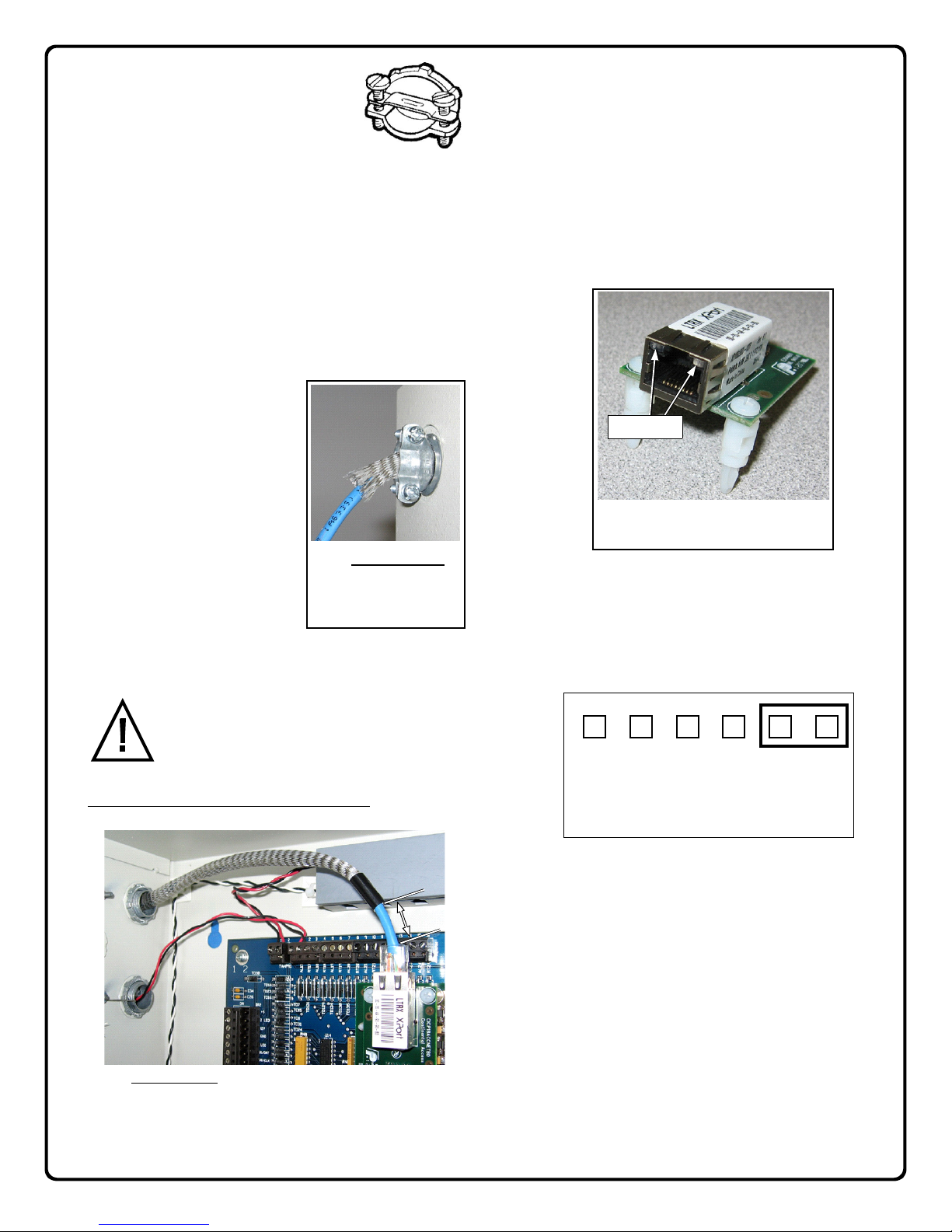
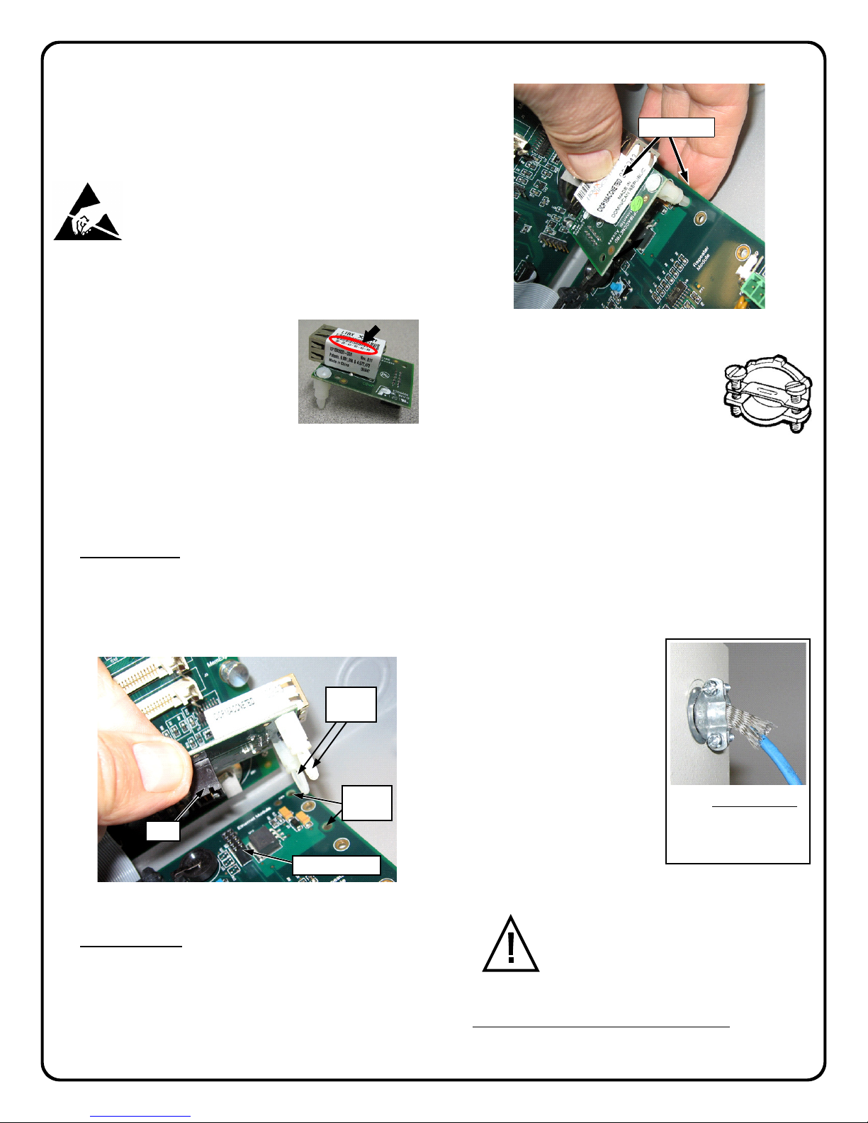
1. Find the MAC address located on
the white label wrapped around the
Ethernet plug (circled in Fig. 10 at
right). Write the MAC address here:
_______________________ and
keep this paper in a safe location for
future reference.
2. Before installation, verify that the Accelaterm control panel is
working correctly.
3. Disconnect power to the system, including the battery wires.
4. Align the board: The Ethernet board is mounted in the top
right corner of the Accelaterm Interface board. See Fig. 11.
Carefully align the two Ethernet board snap-lock standoffs
with the two Interface PC board mounting holes. Then align
the Ethernet board plug with the Interface board receptacle
"JP2" as shown below.
Insert the board: With both standoffs and the plug aligned,
firmly press the Ethernet board into the Accelaterm Interface
board by holding the Interface board with the tips of your fin-
gers and squeezing the Ethernet board as shown Fig. 12.
5. Insert your CAT5/6 Ethernet cable first
through a cable clamp (Fig. 13) and then
through a knockout located on the right
side of the panel enclosure. Pull only
enough of the Ethernet cable into the en-
closure to allow the plug to be easily in-
serted into the Ethernet board receptacle.
6. In the parts bag, find the silver braided
shield. For FCC compliance, this braided shield must be both
secured to the cable clamp and placed over the Ethernet cable
in the interior of the panel enclosure.
Note: The presence of this silver braided shield makes
shielded twisted pair (STP) cable unnecessary. In addition,
unshielded twisted pair (UTP) cable does not need to be
routed in conduit.
Before tightening the cable
clamp, place the braided shield
over the Ethernet cable. Pull the
braided shield out through the
panel knockout and into the ca-
ble clamp. Thus, the braided
shield is grounded to the panel
enclosure by the cable clamp (as
shown in Fig. 14.
7. The Ethernet cable must be covered by the braided shield but
leave about one inch of cable exposed near the
plug. Note that this one inch of exposed cable
should be measured with the Ethernet cable
plugged into the Ethernet board receptacle. If
desired, use electrical tape to cover the end of
the braided shield similar to the image shown in the Fig. 7
photograph earlier in this manual.
DO NOT cover the plug with the braided shield.
Fig. 10: MAC address location
Fig. 11: Align the two snap-lock standoffs and plug with the Ac-
celaterm Interface board holes and receptacle "JP2".
Two
standoffs
Mounting
holes
Plug
Receptacle "JP2"
Fig. 12: Squeeze to insert the board
Squeeze Here
Fig. 13: Cable
Clamp
Fig. 14: PANEL EXTERIOR:
Both the Ethernet cable and
the braided shield must be
grounded to the panel enclo-
sure by the cable clamp.