Aeropro A240 Owner's manual

AEROPRO CZ
,
Produc
er
of
Light Sport Aircraft
Mladá 835, 687 25 Hluk, Czech Republic
Pilot Operating Handbook
and
Flight Training Supplement
AEROPRO
A2
4
0
Light Sport Aircraft

Aeropro CZ
-
A2
4
0
-
Pilot Operating Handbook and Flight Training Supplement
Sept
ember 20, 2017
0
-
2
Aircraft Type:
A2
4
0
Serial Number:
____
_
____
Registration:
N
_________
Date of Issue:
September 1, 2016
version 1.0
This aircraft was manufactured in accordance with Light Sport Aircraft airworthiness standards
and does
not conform to standard category airworthiness requirements.

Aeropro CZ
-
A2
4
0
-
Pilot Operating Handbook and Flight Training Supplement
Sept
ember 20, 2017
0
-
3
RECORD OF REVISIONS
Any revisions or amendments to the present manual shall be issued in the form of bulletins with attached
new pages. It is in the interests of every user to enter such re
vision into the table of revisions and to
replace the existing page by the new one. The revised or corrected text shall be indicated by a vertical line
on left page margin and the page shall bear revision number and date of its issue.
Rev. No.
Pages Affec
ted
Date of Issue
Bulletin Number
New Page Inserted On, Signature

Aeropro CZ
-
A2
4
0
-
Pilot Operating Handbook and Flight Training Supplement
Sept
ember 20, 2017
0
-
4
TABLE OF CONTENTS:
RECORD
OF
REVISIONS
................................
................................
..............
..
0
-
3
0.
GENERAL INFORMATION
................................
................................
.....
0
-
7
0.1
I
NTRODUCTION
................................
................................
.......................
0
-
7
0.2
C
ERTIFICATION
B
ASIS
................................
................................
.............
0
-
7
0.3
M
ANUFACTURER
................................
................................
....................
0
-
7
0.4
W
ARN
ING
,
C
AUTION AND
N
OTE
................................
..............................
0
-
7
1.
AIRPLANE AND SYSTEMS
DESCRIPTION
....................
....................
.
1
-
8
1.1
E
NGINE
...............................................................................
....................
1
-
9
1.2
P
ROPELLER
................................
................................
.............................
1
-
9
1.3
F
UEL AND FUEL CAPACIT
Y
................................
................................
......
1
-
9
1.4
O
IL
................................
................................
................................
........
1
-
11
1.5
O
PERATING WEIGHTS
&
LOADING
(
OC
CUPANTS
,
BAGGA
GE
,
FUEL
).........
1
-
11
1.6
C
OCKPIT OVERVIEW
................................................................
...............
1
-
12
1.7
A
IRCRAFT
E
LECTRICAL
S
YSTEM
................................
...........................
1
-
17
1.8
Electric Backup Fuel Pump..
…………………………………………………….
1
-
1
7
1.9 Additional Equipment........................................................................... 1
-
17
2.
OPERATING LIMITATION
S
................................
................................
.
2
-
18
2.1
S
TALL SPEED AT MAXIMU
M TAKE
-
OFF WEIGHT
(VS
AND
VSO)
............
2
-
18
2.2
F
LAPS EXTENDED SPEED
RANGE
(VSO
TO
VFE)
................................
...
2
-
18
2.3
M
AXIMUM MANEUVERING S
PEED
(VA)
................................
................
2
-
19
2.4
N
EVER EXCEED SPEED
(VNE)
................................
...............................
2
-
19
2.5
C
ROSSWIND AND WIND LI
MITATION
................................
......................
2
-
19
2.6
S
ERVICE CEILING
................................
................................
..................
2
-
19
2.7
L
OAD FACTORS
................................
................................
.....................
2
-
19
2.8
P
ROHIBITED MANEUVERS
................................
................................
......
2
-
19
2.9
O
THER
L
IMITATIONS
................................
................................
.............
2
-
20
3.
WEIGHT AND BALANCE I
NFORMATION
................................
........
3
-
21
3.1
I
NSTALLED EQUIPMENT L
IST
................................
................................
.
3
-
21
3.2
C
ENTER OF GRAVITY
(CG)
RANGE AND DETERMINAT
ION
......................
3
-
21
3.2
.1
Weight and balance determination for flight
...............................
3
-
21
3.2.2
Detailed calculation of CG position
…………………………...…. 3
-
21
4.
PERFORMANCE
................................
................................
......................
4
-
24
4.1
T
AKE
-
OFF AND LANDING DIST
ANCES
................................
.....................
4
-
24
4.2
R
ATE OF CLIMB
................................
................................
.....................
4
-
24
4.3
C
RUISE SPEEDS
................................
................................
.....................
4
-
24
4.4
RPM
................................
................................
................................
.....
4
-
24
4.5
F
UEL CONSUMPTION
................................
................................
.............
4
-
25
4.6
O
THER PERFORMANCE DAT
A
................................
................................
4
-
25
5.
NORMAL PROCEDURES
................................
................................
.......
5
-
26
5.1
P
REFLIGHT INSPECTION
................................
................................
.........
5
-
26
5.1.1
Daily preparation
................................
................................
........
5
-
26
5.1.2
Preflight Inspection
................................
................................
......
5
-
28
5.2
E
NGINE STARTING
................................
................................
.................
5
-
28
5.2.1
Use of External Power Supply
................................
.....................
5
-
29
5.2.2
Engine Starting
................................
................................
............
5
-
29
5.3
T
AXIING
................................
................................
................................
5
-
29
5.3.1
Prior to taxiing
................................
................................
.............
5
-
29

Aeropro CZ
-
A2
4
0
-
Pilot Operating Handbook and Flight Training Supplement
Sept
ember 20, 2017
0
-
5
5.3.2
Taxiing
…………………………………………………………………
5
-
29
5.3.3
Engine warm
-
up, power check
.....................
................................
5
-
3
0
5.4
N
ORMAL TAKE
-
OFF
................................
................................
...............
5
-
30
5.4.1
Prior to tak
e
-
Off
................................
................................
...........
5
-
30
5.4.2
Take
-
off
................................
................................
........................
5
-
31
5.5
B
EST ANGLE OF CLIMB S
PEED
(VX)
................................
......................
5
-
31
5.5.1
Climbing
................................
................................
.......................
5
-
31
5.6
B
EST RATE OF CLIMB SP
EED
(V
Y
)
................................
.........................
5
-
32
5.6.1
Climbing
................................
................................
.......................
5
-
32
5.7
C
RUISE
................................
................................
................................
..
5
-
32
5.7.1
Cruise Flight
................................
................................
................
5
-
32
5.8
A
PPROACH
................................
................................
............................
5
-
32
5.8.1
Descent
................................
................................
.........................
5
-
32
5.8.2
Downwind
................................
................................
....................
5
-
32
5.9
N
ORMAL LANDING
................................
................................
................
5
-
33
5.9.1
On base leg
................................
................................
..................
5
-
33
5.9.2
On final
................................
................................
........................
5
-
33
5.9.3
Landing
................................
................................
........................
5
-
33
5.9.4
After landing
................................
................................
................
5
-
33
5.9.5
Engine stopping
................................
................................
...........
5
-
33
5.9.6
Post
-
flight check
................................
................................
..........
5
-
34
5.10
S
HORT FIELD TAKE
-
OFF AND LANDING PROC
EDURES
.............................
5
-
34
5.11
A
BORTED LANDING PROCE
DURES
................................
.........................
5
-
34
5.12
I
NFORMATION ON STALLS
,
SPINS AND ANY OTHER
USEFUL PILOT INFORMA
TION
....
5
-
34
5.12.1
Rain
................................
................................
..............................
5
-
34
6.
EMERGENCY PR
OCEDURES
................................
...............................
6
-
35
6.1
I
NTRODUCTION
................................
................................
.....................
6
-
35
6.2
E
NGINE
F
AILURE AND
E
MERGENCY LANDINGS
................................
.....
6
-
35
6.2.1
Engine failure during take
-
off Run
................................
..............
6
-
35
6.2.2
E
ngine failure during take
-
off
................................
......................
6
-
35
6.2.3
In
-
flight engine failure
................................
................................
.
6
-
35
6.2.4
Additional information for engine failure and emergency landing procedures....
6
-
36
6.2.5
Carburetor icing
................................
................................
..........
6
-
36
6.3
I
N
-
F
LIGHT
E
NGINE
S
TARTING
................................
...............................
6
-
37
6.4
F
IRES
................................
................................
................................
....
6
-
37
6.4.1
Engine fire on the ground
................................
............................
6
-
37
6.4.2
Engine fire during t
ake
-
off
................................
...........................
6
-
37
6.4.3
Engine fire in
-
flight
................................
................................
......
6
-
38
6.4.4
Cockpit or electrical fire
................................
..............................
6
-
38
6.5
G
LIDING
................................
................................
................................
6
-
38
6.6
P
RECAUTIONARY
L
ANDING
................................
................................
...
6
-
38
6.7
B
LOWN
-
O
UT
T
IRE
L
ANDING
................................
................................
.
6
-
39
6.8
D
AMAGED
L
ANDING
G
EAR
L
ANDING
................................
....................
6
-
39
6.9
V
IBRATIONS OR OTHER E
NGINE PROBLEMS
................................
...........
6
-
39
6.10
I
NADVERTENT ICING EN
COUNTER
................................
.........................
6
-
39
6.11
E
XTREME TURBULENCE EN
COUNTER
................................
....................
6
-
40
6.12
E
LECTRICAL SYSTEM MAL
FUNCTIONS
................................
...................
6
-
40
6.12.1
Charging
indicator is illuminated
................................
................
6
-
40
6.13
I
NADVERTENT
R
ESCUE
S
YSTEM
S
TALL AND SPIN RECOVE
RY
...............
6
-
40
6.13.1
The following general procedure should be followed should a stall occur:
6
-
40
6.13.2
The following general procedure should
be followed should a spin occur:
6
-
40
6.14
RESCUE SYSTEM …………………………………………………...6
-
4
0
6.14.1
Operation of Rescue System………………………………………
.
….6
-
4
0

Aeropro CZ
-
A2
4
0
-
Pilot Operating Handbook and Flight Training Supplement
Sept
ember 20, 2017
0
-
6
7.
AIRCRAFT GROUND HAND
LING AND SERVICING
......................
7
-
41
7.1
S
ERVICING FUEL
,
OIL
,
COOLANT
................................
............................
7
-
41
7.1.1
Servicing fuel
................................
................................
..............
7
-
44
7.1.2
Servicing oil
................................
................................
.................
7
-
41
7.1.3
Servicing coolant
................................
................................
.........
7
-
41
7.2
L
ANDING GEAR TIRE DIM
ENSION AND
PRESSURE
................................
...
7
-
42
7.3
T
OWING AND TIE
-
DOWN INSTRUCTIONS
................................
................
7
-
42
7.3.1
Aircraft towing instructions
................................
.........................
7
-
45
7.3.2
Aircraft tie
-
down instructions
................................
......................
7
-
42
7.4
P
ARKING BRAKE OPERA
TION
..................
...............................
..................
7
-
42
8.
REQUIRED PLACARDS AN
D MARKINGS
................................
.........
7
-
43
8.1
A
IRSPEED INDICATOR RA
NGE MARKINGS
................................
..............
7
-
43
8.2
O
PER
ATING LIMITATION ON
INSTRUMENT PANEL
................................
..
7
-
44
8.3
P
ASSENGER WARNING
................................
................................
...........
7
-
44
8.4
“N
O INTENTIONAL SPINS
”
................................
................................
......
7
-
44
8.5
M
ISCELLANEOUS PLACARD
S AND MARKINGS
................................
........
7
-
44
9.
SUPPLEMENTARY INFORM
ATION
................................
...................
8
-
45
9.1
F
LIGHT FAMILIARIZATIO
N PROCEDURES
................................
................
8
-
45
9.2
P
ILOT OPERATING ADVIS
ORIES
................................
..............................
8
-
45
9.3
F
URTHER
I
NFORMATION
................................
................................
.......
8
-
45
10. APPENDIX
10.1 Airplane weight and balance statement………………………………..10
-
1

Aeropro CZ
-
A2
4
0
-
Pilot Operating Handbook and Flight Training Supplement
Sept
ember 20, 2017
0
-
7
0.
General information
0.1
Introduction
This handbook is provided with your aircraft to allow you to attain as much knowledge about the aircraft
and its opera
tion as possible. This manual is following
ASTM F2746
-
09 Standard Specification for Pilot’s
Operating Handbook (POH) for Light Sport Airplane
. Read this manual thoroughly before your first flight
and make sure you understand all the information contained w
ithin. This aircraft is equipped with a non
-
certified engine that meets the ASTM F
-
2339 engine standard. Flying this aircraft must always be done
with the possibility of a safe landing due to loss of engine power.
Pay attention to the fact that you as the
pilot are fully responsible for the safety of your passengers and
persons or property on the ground.
0.2
Certification basis
This aircraft was manufactured in accordance with Light Sport Aircraft airworthiness standards and does
not conform to standard categ
ory airworthiness requirements.
0.3
Manufacturer
A
eropro
CZ
Mladá 835
687 25 Hluk
Czech Republic
0.4
Warnings, cautions and notes:
In this handbook the following is used to highlight especially important information:
WARNING
Information which could prevent
personnel injury or loss of life
CAUTION
Information which could prevent damage to equipment
NOTE
Information of special importance to pilots

Aeropro CZ
-
A2
4
0
-
Pilot Operating Handbook and Flight Training Supplement
Sept
ember 20, 2017
1
-
8
1.
Airplane and systems description
The
Aeropro
A2
4
0
is an
S
-
LSA
aircraft
designed as a high
-
wing mono
plane. A two
-
spar wing is equipped
with
external airfoil
flaperons. Fuselage is an open truss structure welded of
chromoly
steel tubes. Tail
unit is formed of a lattice
-
work tube frame. The
A2
4
0
is equipped with t
ricycle
-
gear with a steerable
nosewheel
.
Wing area including flaperon
s
…………………
………
……………..
122.53 sq. ft
Chord length (inc
luding flaperon)………………
……….
……………
4.265 ft
Win
g loading...........................................................................
10.1 lbs/sq. ft
Power loading........
............................
..............................
........
12.35 lbs/HP
Aspect
-
ratio
.......................................
......................................
6.74
:1
Propeller
clearance..........................
..
........................
...
...
.........
1
1
.5
inches

Aeropro CZ
-
A2
4
0
-
Pilot Operating Handbook and Flight Training Supplement
Sept
ember 20, 2017
1
-
9
1.1
Engine
The
A2
4
0
is powered by the Rotax 912ULS
100
-
hp
engine. It is a four
-
cylinder, four
-
stroke, horizontally
-
opposed, center
-
camshaft engine with overhead valves. Engine cooling is of a combined type; cylinder
heads ar
e water
-
cooled while cylinders are air
-
cooled. The engine has dry
-
sump lubrication. The ignition
system is a dual, electronic and capacitor flywheel magneto type. The engine is equipped with an electric
starter, AC generator and a mechanical fuel deliver
y pump. The propeller is driven by an integrated
reduction gearbox with mechanical damping.
Engine manufacturer
.....................................
.
..
Rotax GmbH., Austria
Engine model.........................
.............................
Rotax 912ULS
Ma
x. power
-
take
-
off............
...... 100 hp
-
continuous......
....
.
..
94 hp
Max. engine speed (MSL)
-
take
-
off................
5800 RPM (max. 5 min)
-
continuous.....
..
...
.
5500 RPM
Max. cylinder head temperature.......
..............................
....
....
280
F
Min. o
il temperature………………………………………
….
…
..
..
12
2
F for full
-
throttle operation
Normal ope
rating temperature……………………………
….
...
…
190
–
230
F
M
ax. oil temperature....................................................
.
...
.....
.
..
300
F
M
inimum oil pressure……………...................…
............
....
.
..
…
12 psi min oil pressure below 3,500 rpm
M
aximum oil pressu
re (cold start only)…………………
…..
..
.
.
..
103 psi
N
ormal oil pressure range..........................
.............
.........
...
.
..
29
–
73 psi
Oi
l consumption
…………………………………………
…
….
...
max 0.06 quarts/hour
Fuel pressure
-
minimum...............
...........................
.
....
.18 bar (2.2 psi)
-
maximum.............
..............................
..
.
.4
bar (5.8
psi)
Pr
opeller gearbox reduction ratio....
..............................
.
.
.....
...
.
2.43 : 1
For more details see
Operator’s Manual f
or all versions of
Rotax 912
supplied with the engi
ne.
WARNING
This aircraft is equipped with a non
-
certified engine that
meets
the
ASTM F
-
2339
engine standard.
Flying this aircraft must always be done with the possibility of a safe landing due
to loss of engine power. The pilot is fully responsible for consequences of such
failure.
1.2
Propeller
The
standard
propeller is manu
factured by
Woodcomp
in the
Czech Republic
.
The propeller is a
3
-
blade,
ground
-
adjustable prop.
Propeller
is 68" diameter.
For additional propeller information see
Operators Manual and Technical description
supplied with the
propeller.
1.3
Fuel and fuel cap
acity
Fuel tank capacity
-
wing tanks
(two)............................
.
....
10.6 U.S. gallons each
-
central connecting tank
(header tank)
...........................
1.
3
U.S. gallons
Max. fuel quantity
..............................................
...............
22.
5
U.S. gallons
Usable fuel quantity.........................
...............................
.
2
2
.
0
U.S. gallons
Unusable fuel quantity
......................................................
0.
5
U.S. gallons
Fuel specifications…
……....
..
p
remium unleaded auto fuel (Standard Spec. for Automotive
Spark
-
Ignition Engine, Fuel
, ASTM D 4814) or AVGAS 100 LL

Aeropro CZ
-
A2
4
0
-
Pilot Operating Handbook and Flight Training Supplement
Sept
ember 20, 2017
1
-
10
Due to the higher lead content in AVGAS, the wear of the valve seats, deposits in th
e combustion
chamber and lead sediments in the lubrication system will increase. Therefore, use AVGAS only if you
encounter problems with vapor lock or if other fuel types are not available.
For additional information concerning fuel specification consult
the
Operator’s Manual for all versions
of Rotax 912
supplied with the engine.
The fuel system consists of two 10.6 U.S. gallon
s wing tanks, a 1.
1
U.S. gallons
central header tank
behind the left seat, a fuel drain valve positioned below the header tank,
three fuel valves, one fuel filter,
an engine driven fuel pump
,
a backup electric fuel pump (not shown in the diagram below),
and the
connecting fuel lines.
The fuel is gravity
-
fed from the right
-
hand and/or left
-
hand wing tank, through the wing tank fu
el values,
into the central header tank. The fuel is then further directed from the central tank through the fuel filter
and the electric fuel boost pump through the main fuel valve and to the mechanical fuel pump on the
engine which then delivers the fuel
to the carburetors.
The amount of fuel in each tank is indicated by a visual sight tube which is a part of each tank. Minimum
fuel quantity in the central tank is indicated by a red warning light on the instrument panel. The remaining
fuel (0.9 U.S. gall
on), is enough for approximately 10 minutes of flight. The low fuel warning light can be
tested at any time by pushing the control button next to the light on the instrument panel. If the red light
does not light up when the control button is pushed and he
ld, consider the bulb to be blown out and so do
not rely on the minimum fuel quantity warning light:
-
In this case, make a more conservative estimate for
fuel on board, regularly check the fuel quantity in wing tanks and land as soon as you are not confid
ent of
the fuel quantity in the wing tanks.
Although it is normal to leave both wing tank fuel values open, occasionally, one tank will drain faster than
the other. Should this situation occur, manipulate the fuel tank valves to ensure continuous flow of
fuel to
the engine is maintained.

Aeropro CZ
-
A2
4
0
-
Pilot Operating Handbook and Flight Training Supplement
Sept
ember 20, 2017
1
-
11
The fuel drain valve outlet is located behind and below the left seat on the outside of the fuselage; to
check for water and dirt, push the neck of the drain pipe gently upwards, into the fuselage and
subsequently a fuel
sample can be taken.
For refuelling information see section
7.1
1.4
Oil
Oil tank capacity………………………………………………….
3.2 quarts
Maximum oil quantity…………………………………………….
2.6 quarts
Minimum o
il quantity…………………………………………….
2
.1 quarts
Oil specification:
Use semi
-
synthetic 10w40 motorcycle type oil of a registered brand name. Caution
:
When selecting the
most suitable lubricants refer to the additional information in the Rotax Service Information SI
-
18
-
1997.
Normally the recomme
nded oil is Aeroshell Sport 4 (a 10w40 semi
-
synthetic oil)
.
—
Use only oil with API classification "
SF
" or "
SG
"!
—
Due to the high stresses in the reduction gears, oils with gear additives such as high
performance motor cycle oils are required
—
Because of the
incorporated friction clutch, oils with friction modifier additives are
unsuitable as this could result in a slipping clutch during normal operation.
—
Heavy duty 4
-
stroke motor cycle oils meet all the requirements. These oils are normally
not mineral oils
but
are
semi
-
or full synthetic oils.
—
Oils primarily for Diesel engines are
insufficient
due to
high temperature properties
and additives which favor clutch slipping, generally therefore are unsuitable.
CAUTION
:
If the engine is mainly run on AVGAS
mor
e frequent
oil changes will be required. See Rotax
Service Information SI
-
18
-
1997.
For additional information concerning oil system consult
Operator’s Manual for all versions of Rotax
912
supplied with the engine.
The maximum and minimum oil level is indi
cated by two marks on the dipstick in the oil tank.
1.5
Operating weights and loading (occupants, baggage, fuel, ballast)
Empt
y weight (wit
h typical options).......................................
6
5
5
lbs
Max. take
-
off weight..............................
...............................
1235 lbs
Max. landing weight...............................................................
1235 lbs
Max. fuel weight………………………………………………….
135 lbs
Max. baggage
weight in baggage compartm
ent…………….
50
lbs
Maximum num
ber of p
ersons on board………………….......
2
Minimum crew weight……………………………………………
121 lbs
WARNING
Make sure that above
-
mentioned weight limits are strictly followed.
Structural failures which result from
overloading of the aircraft may
be dramatic and catastrophic.
The additional stress placed on the structural parts by overloading can accelerate the occurrence of metal
fatigue failures. Also
,
flight characteristics might change significantly when aircraft is
overloaded. Take
-
off
and landing distance is significantly longer for overloaded aircraft. Overloading of the
aircraft is one of the
causes of accidents.

Aeropro CZ
-
A2
4
0
-
Pilot Operating Handbook and Flight Training Supplement
Sept
ember 20, 2017
1
-
12
1.6
Cockpit overview
LAYOUT OF CONTROLS AND INSTRUMENTS
(see following pages for details conc
erning Figures 1
-
9)
Fig.1
a
irspeed indicator
1. control stick
19. area for GPS or iPad installation
Fig.2
e
ngine start up
2. rudder pedals
20. air vents
Fig.3
m
ain fuel valve
3. flaperon control knob
21.
EIS engine instrumentation
Fig.4 EIS en
gine instrument
4. elevator trim control knob
22.
intercom
Fig.5
c
entral control panel
5. main fuel valve
23. ELT panel controller
Fig.6
f
laps, trim
6.
boost pump switch
24
. Rotax fuel pressure gauge
Fig.7 s
witches and
circuit breakers
7.
keye
d igntion switch
2
5.
cigarette lighter type power socket
Fig.8
c
ontrol lights
8. magneto on/off switches
26.
circuit breaker for power socket
Fig.9
d
oor lock mechanism
9. airspeed indicator
27.
mapbox
10.
altimeter/VSI
28.
throttle
11. tran
sponder
29.
carb heat knob
12. radio
30.
cockpit heat knob
13. EFIS/attitude indicator (optional)
31.
oil cooler flap knob
1
4. annunciator test button
32
brake lever
15. low fuel level warning light
33.
choke lever
16. low voltage war
ning light
34.
switches
17. EIS warning light
35.
circuit breakers
18.
compass

Aeropro CZ
-
A2
4
0
-
Pilot Operating Handbook and Flight Training Supplement
Sept
ember 20, 2017
1
-
13
List of typical installed instruments and other equipment including options:
Type
Serial No.
a
irspeed indicator
ASI 150 M
-
3
a
ltimeter
and vertical speed indicator
MGL ALT
-
3 electronic
s
lip
i
ndicator
(in EFIS)
m
agnetic compass
CM
-
13
f
uel pressure
BDT1/31/B
ELT
ELT345
r
adio
-
intercom
ATR833
-
OLED
and PM1000II
t
ransponder with encode
r
Funkwerk Avionics TRT800H
-
OLED
EFIS or
a
ttitude indicator (optional)
Figure 1
-
Airspeed Indicator marking
Figure 2
-
Ignition and master switch
Ignition OFF
Ignition ON

Aeropro CZ
-
A2
4
0
-
Pilot Operating Handbook and Flight Training Supplement
Sept
ember 20, 2017
1
-
14
Figure 3
-
Main Fuel Valve open and closed position
Figure 4
-
EIS Model 4000 for Rotax 912
-
series engines
Display panel description (shown is EIS page 1
-
defau
lt display page)
tachometer
-
engine RPM
OAT
-
outside air temperature
H
2O
–
coolant t
emperature
oil temperature
aircraft hourmeter
EGT
-
exhaust gas temperature (hottest EGT)
oil pressure
Indicator unit alert li
mits max limit
Engine rotation speed (rpm)
..........................
5
6
00 ................. 5800
EGT/Exhaust gas temperature (ºF)
..............
16
5
0 .................. 1850
H2O
/c
oolant
temperature (ºF)
.....................
2
28
................... 2
4
8
Oil temperature, (ºF)
................................
.....
260 ..................
. 300
Oil pressure, max (psi)
................................
.
8
4
................... 100
Oil pressure, min (psi)
................................
..
28 .................. 12 (minimum)
Oil pressure, normal (psi)....
......
..
..
. 29
-
72
Aeropro CZ
-
A2
4
0
-
Pilot Operating Handbook and Flight Training Supplement
Sept
ember 20, 2017
1
-
15
T
he
EIS
system not only alerts you when reaching an actual system lim
it, it also has the
capability to provide alerts when reaching a Warning Limit that is just short of the actual non
-
permissible limit
.
When one or more Warning Limits are exceeded
–
the corresponding value blinks on the EIS
display, the alarm lamp on the i
nstrument panel blinks
.
When
the pilot presses the “Next/Ack”
button on the EIS,
the
Alarm Lamp goes steady until the out of tolerance condition is corrected.
When the actual limit is reached, the EIS reacts in the same manner as a new fault, except the
alarm lamp blinks at longer intervals. The pilot must press Next/Ack again to turn both the
blinking alarm light and EIS display to steady.
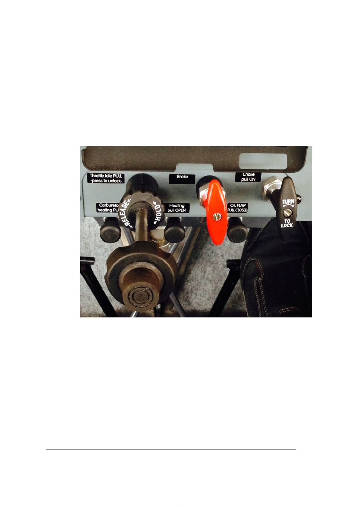
Figure 5
–
c
entral panel
Note: Rotate throttle lever
knob
for fine power settings (clockwise to increase power,
counterclockwise to reduce
power), for larger changes push/pull throttle when the button is pressed and held
.

Aeropro CZ
-
A2
4
0
-
Pilot Operating Handbook and Flight Training Supplement
Sept
ember 20, 2017
1
-
16
Figure 6
–
Flaps and trim
Figure 7
–
Switches and fuses panel
(older panel shown...)
Figure 8
–
Control lights and fuel reserve bulb check
button

Aeropro CZ
-
A2
4
0
-
Pilot Operating Handbook and Flight Training Supplement
Sept
ember 20, 2017
1
-
17
Figure 9
–
Door locking mechanism
The battery (Powersafe SBS8, 12v, 7 ah) is located behind the right
-
hand pilot’s seat. Nominal voltage in
aircraft system is 13.5 to 14.2 V. The engine is equipped with an integrated AC generator with external
rectifier
-
regulator (12 V, 20A DC).
1.7
Aircraft lighting equipment
The A220 features the Whelen LED wingtip lights. This system consists of a white rearward
-
facing LED
lights and a flashing LED strobe light on the side of both wingtips, a green forward
-
faci
ng LED light on the
right wingtip and a red forward
-
facing light on the left wingtip. There is also a landing light fitted to the
lower nose cowling which also acts as a taxi light. Power for the light system is taken from the aircraft's
main power supply.
NOTE:
The A240 is NOT approved for night flight, and the exterior aircraft lighting does not comply with all
the FAR requirements for night flight.
1.8
Electric fuel pump
The
A2
4
0
is equipped with an electric fuel pump with an on/off switch and "on" indicato
r light on the
instrument panel. The electric fuel pump serves as a booster or backup to the engine
-
driven mechanical
fuel pump.
The electric fuel pump should be used at any time when the sudden failure of the
engine
-
driven mechanical fuel pump and a los
s of fuel pressure could cause a loss of engine
power and compromise safety. Normally this will mean utilizing the electric fuel pump during
takeoff, during climb
-
out to a safe minimum altitude, during any low
-
altitude operations, and
during landing.
1.9
Add
itional equipment
reserved

Aeropro CZ
-
A2
4
0
-
Pilot Operating Handbook and Flight Training Supplement
Sept
ember 20, 2017
2
-
18
2.
Operating limitations
Airspeed indicator system calibration:
As requested by ASTM F
-
2245
-
04
§9.1
all flight speeds are presented as calibrated airspeeds in miles
per hours (MPH). As the calibrated airspeed cannot be usually de
termined by a simple reading of the
aircraft airspeed indicator, corresponding Indicated airspeeds in miles per hours (MPH) are also
presented in this document. All airspeed values in this handbook assume no instrument error.
2.1
Stall speed at maximum take
-
o
ff weight (V
S
and V
SO
)
Aircraft configuration
Stall speed
–
angle of bank 0°
MPH
(Indicated Air speed)
MPH
(Calibrated Air speed)
Flaps down (V
so
)
4
1
45
Flaps up (V
s
)
.
49
.
50
WARNING
The stall speed mentioned above are with wings level. Once any
angle of bank
(e.g. turn) is encountered the stall spe
ed is significantly increasing.
e
xample: angle of bank
60° …….
V
S
= 73 MPH
The more bank
–
the higher the stall speed. This simple rule is especially important when a turn at
maximum permitted angle
of bank (60°) is performed. Do not start the turn until you have sufficient
airspeed reserve
–
recommended entry speed is 92 MPH. Full throttle is also essential to have sufficient
thrust reserve as the drag is
increasing during a steep turn.
2.2
Flaps extend
ed speed range (V
SO
to V
FE
)
MPH
(Indicated Air Speed)
MPH (Calibrated Air Speed)
Lower limit
41
45
Upper limit
93
90
MPH
(Indicated Air
speed)
MPH
(Calibrated Air
speed)
40
44
46
48
57
59
69
69
81
79
92
89
104
99
115
109

Aeropro CZ
-
A2
4
0
-
Pilot Operating Handbook and Flight Training Supplement
Sept
ember 20, 2017
2
-
19
2.3
Maximum maneuvering speed (V
A
)
MPH
(Indicated Air Speed)
MPH
(Calibrated Air Speed)
Max. maneuvering speed (V
A
)
109
104
2.4
Never
exceed speed (V
NE
)
MPH
(Indicated Air Speed)
MPH (Calibrated Air Speed)
Never exceed speed
(V
NE
)
143
134
2.5
Crosswind and wind limitation
Maximum permitted wind speed components for take
-
off and landing:
m
ax. headwind ………………….……………..............
28 mph
(25 knots)
c
rosswind……………………………………………
.
.
….
17 mph (15 knots)
tail wind………………………………………………
..
….
7 mph (6 knots)
Crosswind take
-
offs and landings require training and experience, the higher crosswind component, the
better your skill must be. Do not fly with
out proper experience when the wind speed is approaching the
limit.
Avoid take
-
offs with a tail wind when possible
–
the total take
-
off distance is significantly longer and longer
ground distance is required to gain altitude.
When landing with a tail win
d the aircraft ground speed is higher resulting in longer landing distance.
2.6
Service ceiling
Service ceiling
................................
................................
..
14,760 ft (standard day)
WARNING
Oxygen mask and/or other equipment
as
required to reach
maximum
ceiling, consult respective re
gulations.
2.7
Load factors
Flaps up:
Maximum positive
load factor
(measured at CG)
………..……
+4 Gs
Maximum negative
load factor
(measured at CG)
……………
-
2 Gs
Flaps down:
Maximum positive
load factor
(measured at CG)
…………….. +
2 Gs
Maximum negative
load factor
(m
easured at CG)
…………….
0 Gs
2.8
Prohibited maneuvers
WARNING
Aerobatics and intentional spins are prohibited.
Maximum angle of bank
: 60°

Aeropro CZ
-
A2
4
0
-
Pilot Operating Handbook and Flight Training Supplement
Sept
ember 20, 2017
2
-
20
2.9
Other Limitations
WARNING
No s
moking
.
WARNING
Flights with rear
cockpit cover
removed are prohibited
.
WARNING
Flights at ambient temperature between 14
F and 32
F are permitted only
under no icing conditions and when the carburetor
heating is activated.
WARNING
IFR flights and flying in clouds is prohibited.
Night Flights are prohibited
.
Flight into know icing conditions is prohibited
.
This aircraft is not certified for operation in IMC (Instrument meteorological conditions). Alw
ays stay clear
of clouds and have visual contact with the ground. Follow the airspace classification regarding distance
from clouds. Always evaluate weather during your flight and try to get weather information from your
destination using radio whenever po
ssible. When weather is deteriorating make a diversion or turn back
before the low cloud base and/or low visibility are critical. The aircraft is not certified to be flown at night.
Table of contents
Other Aeropro Aircraft manuals


