Aeropro CZ A240 User manual

Aeropro CZ A240 /A220
MAINTENANCE MANUAL
Aeropro CZ A240/A220 MAINTENANCE MANUAL
standard with Rotax 912ULS engine, also
with section for A220 taildragger, and
with section for optional Rotax 914UL turbo engine

Maintenance Manual
AEROPRO CZ
0-1
Maintenance Manual
March 21, 2020
List of effective pages
Insert latest changed pages. Destroy superseded pages.
Note: Changed pages are indicated by the marking “changed” at the bottom of the page.
Dates of issue for original and changed pages are:
March 21, 2020
Total pages in this publication is consisting of the following:
Page No. Change No.
Title …………………........................ 0
0-1 thru 0-4 …………………….................... 0
1-1 thru 1-8 ………….................................... 0
2-1 thru 2-11 ………....................................... 0
3-1 thru 3-9 …………................................... 0
4-1 thru 4-8 …………................................... 0
5-1 thru 5-12 ………...................................... 0
6-1 thru 6-7 …………................................... 0
7-1 thru 7-4 …………................................... 0
8-1 thru 8-4 …………................................... 0
9-1 thru 9-3 …………................................... 0
10-1 thru 10-23 for 912ULS engine................... 0
10a-1 thru 10a-13 for 914UL turbo engine........... 0
11-1 thru 11-6 for 912ULS engine.................. 0
11a-0 thru 11a-5 for 914UL turbo engine........... 0
12-1 thru 12-2 …….......................................... 0
13-1 thru 13-3 …….......................................... 0
14-1 thru 14-8 …….......................................... 0
15-1 thru 15-9 …….......................................... 0
16-1 thru 16-1 …….......................................... 0
17-1 thru 17-1 …….......................................... 0
18-1 thru 18-1 ……………………..................... 0
19-1 thru 19-2 ................................................ 0
20-1 thru 20-12 .................................................. 0
Upon receipt of the second and subsequent changes to this book, personal responsible for
maintaining this publication in current status should ascertain that all previous changes have been
received and incorporated.

Maintenance Manual
AEROPRO CZ
0-2
Maintenance Manual
March 21, 2020
Table of contents
Section Page
1 General description 1-1
2 Ground handling, servicing, lubrication and inspection 2-1
3 Structures –Fuselage 3-1
4 Structures –Wings and empennage 4-1
5 Structures –Landing gear and brakes 5-1
6 Structures –Aileron and flap control system 6-1
7 Structures –Elevator control system 7-1
8 Structures –Elevator trim control system 8-1
9 Structures –Rudder control system 9-1
10 Engine (standard Rotax 912ULS) 10-1
10A Engine (optional Rotax 914UL turbo). 10a-1
11 Fuel system (standard Rotax 912ULS) 11-1
11A Fuel system (optional Rotax 914UL turbo) 11a-0
12 Propeller 12-1
13 Utility systems 13-1
14 Instruments and instrument system 14-1
15 Electrical systems 15-1
16 Structural repair 16-1
17 Exterior painting 17-1
18 Wiring diagrams 18-1
19 Safety directives and safety monitoring system 19-1
20 A220 taildragger supplement 20-1

Maintenance Manual
AEROPRO CZ
0-3
Maintenance Manual
March 21, 2020
Foreword
This maintenance manual contains factory-recommended procedures and instructions for the ground
handling, servicing and maintaining of the Aeropro CZ A240 tricycle-gear aircraft (and with supplemental
information for the A220 taildragger). Besides serving as a reference for an experienced mechanic, this
manual also covers some step-by-step procedures for the less experienced person. This manual should
be kept in a handy place for ready reference. If properly used, it will better enable the mechanic to
maintain the Aeropro CZ A240/A220 aircraft and thereby establish a reputation for reliable service.
All information contained is based on data available at the time of publication and is supplemented
and kept current by service bulletins published by the Aeropro CZ Company. These bulletins are sent to
all Aeropro Aircraft Dealers so that they have the latest authoritative recommendations for servicing
Aeropro aircraft. Therefore it is recommended that owners of Aeropro aircraft utilize the knowledge and
experience of the factory-trained Dealer Service.
The Aeropro Service Bulletins can be found on the Aeropro web site at... http://www.aeropro.cz
The latest-version Aeropro Inspection Checklist can be found on a web page at…
www.aerotrek.aero/aerotrek-tips.htm

Maintenance Manual
AEROPRO CZ
0-4
Maintenance Manual
March 21, 2020
Common conversions and abbreviations
Units of length 1 mm = 0.03937 in
1 in = 25.4 mm
1 ft = 0.3048 m
Units of area 1 cm2= 0.155 sq in
1 sq in = 6.4516 cm2
Units of volume 1 cm3= 0.06102 cu in
1 cu in = 16.3871 cm3
1 gal (US) = 3.7854 l (dm3)
Units of mass 1 kg = 2.2046 lb
1 lb = 0.45359 kg
Units of force 1 N = 0.224809 lbf
1 lbf = 4.4482 N
Units of pressure 1 bar = 1000 hPa
1 bar = 14.5037 lbf/in2 (psi)
1 lbf/in2 (psi) = 0.0689 bar
1 in HG = 33.8638 hPa
Units of temperature °C = (°F –32) / 1.8
°F = (°C x 1.8) + 32
Velocities 1 m/s = 3.6 kph
1 ft/min = 18.288 m/s
1 m/s = 0.0555 ft/min
1 kts = 1.852 kph
1 kph = 0.53996 kts
Torques 1 Nm = 8.848 In.lb.
1 in.lb. = 0.113 Nm
1 ft.lb. = 1.356 Nm

Maintenance Manual
AEROPRO CZ
1-1
Maintenance Manual
March 21, 2020
note: This Maintenance Manual is for the A240 with standard Rotax 912ULS engine. When the
aircraft is an A220, this Maintenance Manual includes an additional section relevant to the
A220 taildragger. And/or when the aircraft is equipped with the optional Rotax 914UL turbo
engine, this Maintenance Manual includes additional sections relevant for the 914UL engine.
Section 1
General Description
Table of contents Page
1.1 General description………………………………………………….. 1-1
1.2 Description……………………………………………………............ 1-1
1.3 Aircraft specifications………………………………………………… 1-1
1.4 Torque values………………………………………………………… 1-2
1.5 Tire inflation pressures………………………………………………. 1-2
1.6 Approved oils and capacities……………………………………….. 1-2
1.7 Equipment list………………………………………………………… 1-2
1.8 Weight and balance information……………………………………. 1-3
1.8.1 Center of gravity determination………………………….....…… 1-3
1.8.2 CG-calculation………………………………………………........ 1-4
1.9 Sources to purchase parts………………………………………….. 1-6
1.10 Disposable replacement parts……………………………………... 1-7
1.11 General safety information………………………………………….. 1-8
1.12 Reporting possible safety of flight concerns during inspection.... 1-8
1.1 General description
1.2 Description
The Aeropro aircraft, as described in this manual, are conventional high wing aircraft. The
main supporting structure of the fuselage is of lattice-work welded of steel tubes. The A240 aircraft is
a fixed tricycle landing gear with a steerable nose wheel. A two place, side by side seating
configuration is standard. Each aircraft is equipped as standard with a 4-stroke, four-cylinder,
horizontally-opposed, water cooled Rotax 912ULS 100-hp engine, driving a three-blade propeller.
The Rotax 914UL turbo-charged engine is an option.
1.3 Aircraft specifications
Primary specifications of the aircraft, with dimensions based on gross weight, are given in
figure 1-1. If these dimensions are used for constructing a hangar or computing clearances,
remember that such factors as tire pressure or load distributions may result in some dimensions that
are somewhat different from those listed.

Maintenance Manual
AEROPRO CZ
1-2
Maintenance Manual
March 21, 2020
Figure 1-1.
Gross weight........................................................................... 1235 lb
Fuel capacity........................................................................... 22 gal.
Oil capacity.............................................................................. 0.79 gal.
Engine model (Refer to Section 11 for Engine Data)….......... .Rotax 912 ULS
Propeller.................................................................................. 3-blade
Main wheel tires………………………………………........…… 15x6.00x6 (standard tires)
Pressure……………………………………………....... 29 psi (standard tires)
Nose wheel tire…………………………………………….......... 12x4
Pressure……………………………………………....…29 psi
Aileron travel Up....................................................................... 18°, +/- 2°
Down............................................................................ 8.5°, +/- 1°
Wing flap travel......................................................................... 0° to 20°, +/- 2°
Rudder travel Right................................................................... 27°, +/- 2°
Left............................................................................... .27°, +/- 2°
Elevator travel Up..................................................................... 35°, +/- 2°
Down................................................................... 27°, +/- 2°
Elevator trim tab travel Up.......................................................... 15°, +/- 3°
Down...................................................... 50°, +/- 3°
Principal dimensions
Wing span....................................................................... 29.9'
Length with prop spinner................................................. 18.5'
Vertical stabilizer height.................................................. 7.3'
Track width...................................................................... 4.5'
Tail span.......................................................................... 7.8'
Battery location................................................................ under right seat
1.4 Torque values
A chart of recommended nut torque values is shown in figure 1-2. These torque values are
recommended for all installation procedures contained in this manual, except where other values are
stated. They are not to be used for checking tightness of installed parts during service.
Figure 1-2.
M4……………………………………………………………. 4 Nm / 35 in.lb.
M5……………………………………………………………. 6 Nm / 53 in.lb.
M6……………………………………………………………. 10 Nm / 88 in.lb.
M8……………………………………………………………. 24 Nm / 212 in.lb.
M10…………………………………………………………... 35 Nm / 310 in.lb.
1.5 Tire inflation pressure
Maintain tire pressure at the air pressures specified in figure 1-1. When checking the tire
pressure, examine the tires for wear, cuts, bruises and leakage. Remove oil, grease and mud from
the tires with soap and water.
1.6 Approved oils and capacities
In general we recommend referring to the latest Rotax 912-series engine operators manual
to check for a suitable engine oil. In the United States, only Aeroshell Sport 4 oil is recommended.
1.7Equipment list
In figure 1-5 a list of the factory installed equipment is provided. Additionally installed
equipment and alterations have to be considered when performing the weight and balance
calculation. If a ballistic recovery system is installed from the factory, this is already included in the
factory weight and balance calculation form.

Maintenance Manual
AEROPRO CZ
1-3
Maintenance Manual
March 21, 2020
Figure 1-5
Factory installed typical equipment
airspeed indicator, altimeter, vertical speed indicator, compass, slip indicator
RPM gauge (EIS)
oil pressure gauge (EIS)
oil temperature gauge (EIS)
fuel pressure gauge (Rotax)
H2O (water) temperature gauge (EIS)
exhaust gas temperatures gauge (EIS)
strobe and position lights (Whelen Microburst-III)
radio, intercom and transponder equipment
master, avionics and engine kill (ignition) switches
electrical system including circuit breakers
4-Point safety belts (pilot and passenger)
1.8 Weight and Balance information
To perform a successful weight and balance calculation, the center of gravity "C.G." has to
be determined with all the installed equipment, including engine oil, cooling liquid being considered,
but without fuel. Figure 1-6. shows how to conduct the C.G. determination. All measurements
including a listing of all the installed equipment has to be noted in the separate weight and balance
calculation form (an example is given in figure 1-7). This form has to be placed in the aircraft, so
every pilot will be able to conduct his specific weight and balance calculation prior to each flight.
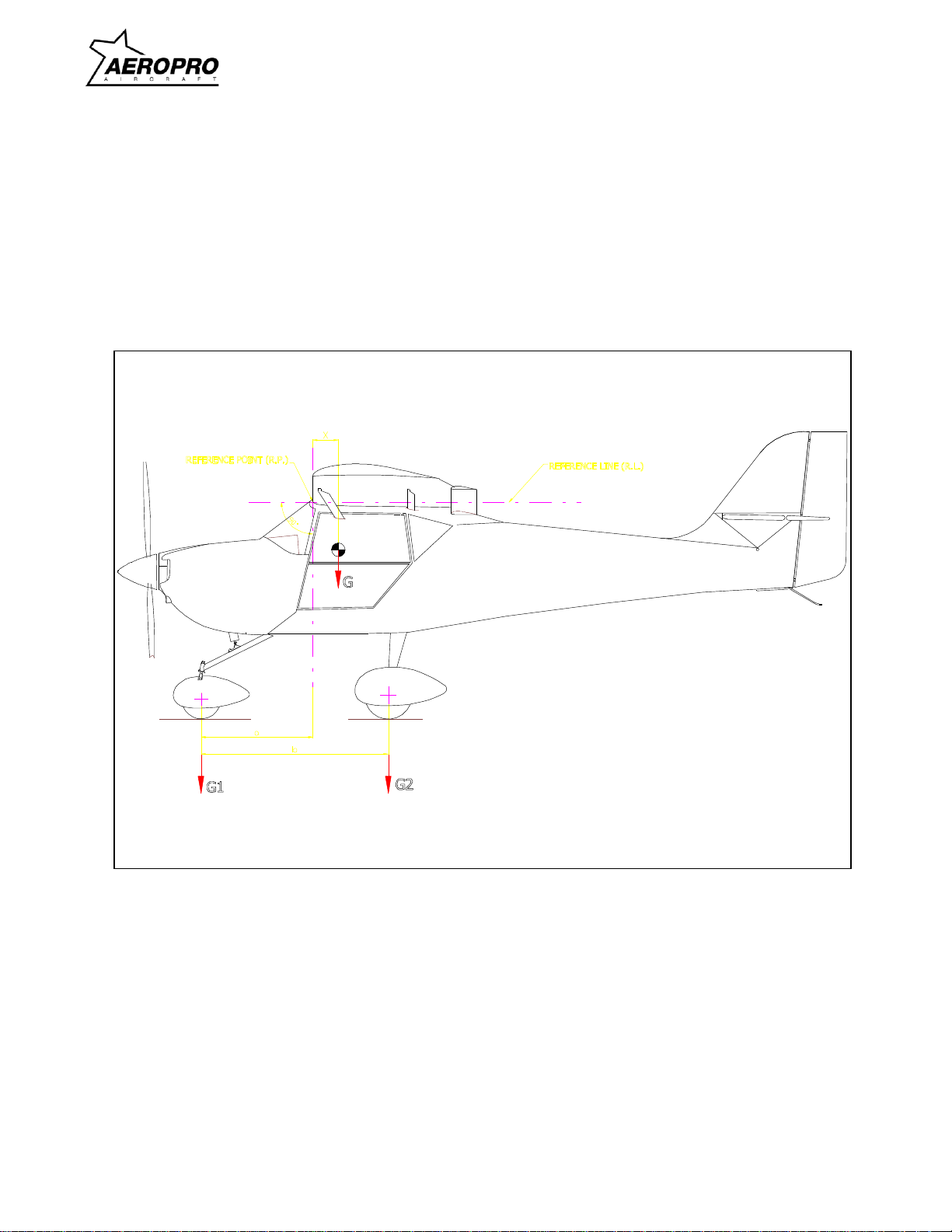
1.8.1 Center of gravity determination
To get the correct values, it is necessary to put the aircraft on three weighing scales located
on a level surface. To get the total weight G you have to add weight G1 and G2. The center of
gravity has to be calculated using this value. The C.G. is located at the distance (X) behind R.P.
(leading edge) near the fuselage (see figure 1-6.).photo showing aircraft weighing
Maintenance Manual
AEROPRO CZ
1-4
Maintenance Manual
March 21, 2020
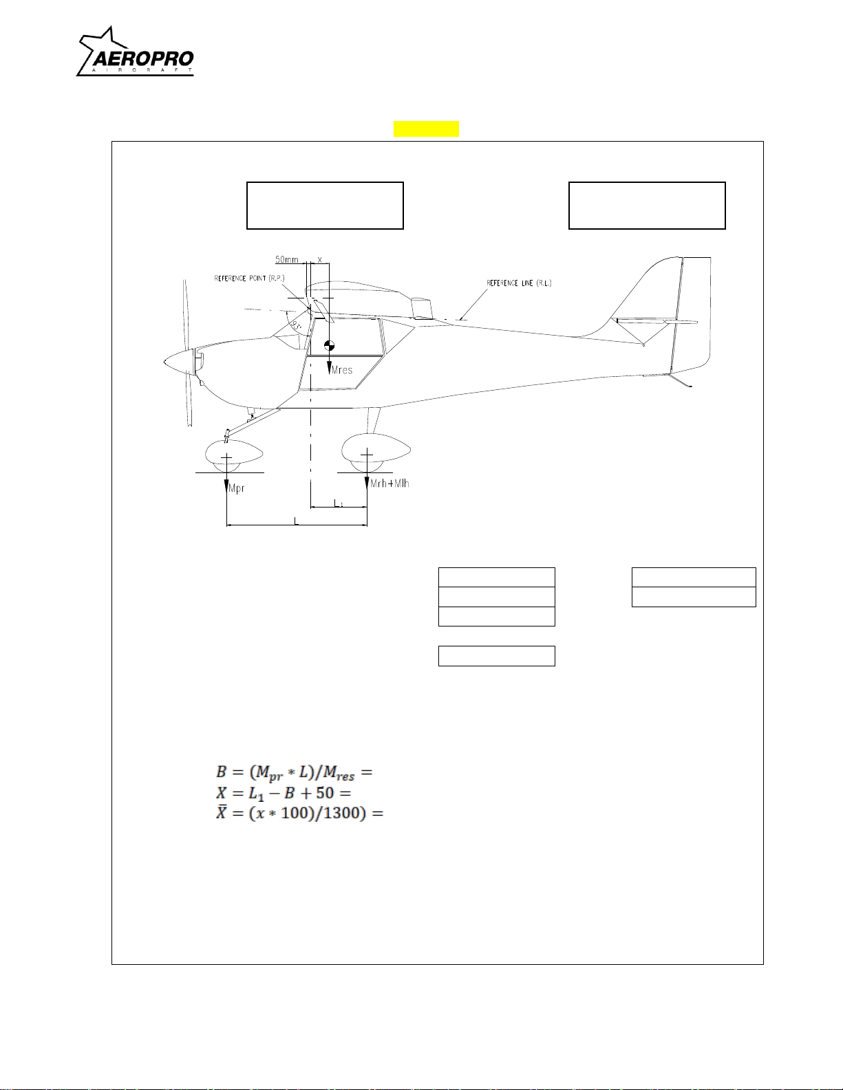
1.8.2 CG - calculation
A specific C.G.-calculation recommendation which has to be carried out prior to each flight is
provided in the Pilot Operating Handbook, Section 4.
Figure 1-6
note: illustration below is for Aeropro aircraft prior to s/n 18106 - see individual aircraft
documents for illustration appropriate for any specific aircraft
Maintenance Manual
AEROPRO CZ
1-5
Maintenance Manual
March 21, 2020
Figure 1-7
WEIGHTAND CG POSITION RECORD
Serial Number: Registration:
Aircraft leveling:
Values Weighed:
Main wheel
Starboard side:
Mrh =
kg
L =
mm
Port side:
Mlh =
kg
L1 =
mm
Nose wheel
Mpr =
kg
Result weight
Mres =
kg
CG position
[mm]
[mm]
[ % MAC ]
Date: Performed by:

Maintenance Manual
AEROPRO CZ
1-6
Maintenance Manual
March 21, 2020
1.9Sources to purchase parts
In figure 1-8. sources to purchase spare parts and disposable parts are given. When in
doubt, ask your Aeropro distributor.
Figure 1-8.
Part description Sources
Airframe and Engine Components……… Aeropro CZ
Hlavní 439, 687 25
HLUK Czech Republic
phone: (+420) 572 582 194
fax: (+420) 572 582 195
e-mail: aeroprocz@seznam.cz
Aerotrek Aircraft
Rollison Light Sport Aircraft, Inc.
34 E. Antioch Road
Bloomfield, IN 47424 USA
phone: 812-384-4972
e-mail: info@aerotrek.aero
web: www.aerotrek.aero
Engine Components………………………… Refer to ROTAX Engine Operator´s
Manual 912 Series, Section 14
or for 914UL turbo engine, Manual 914 Series

Maintenance Manual
AEROPRO CZ
1-7
Maintenance Manual
March 21, 2020
1.10Disposable replacement parts
A listing of disposable replacement parts which require replacement at regular servicing
intervals is given in figure 1-9. Details of where to purchase replacement parts are shown in figure 1-
8. When damage is found on any part of the aircraft please contact your Aeropro distributor when in
any doubt about replacement or repair. No repairs must be done to any of the listed parts due to
flight safety!
Figure 1-9
part description or location part description
engine compartment………………………… Rotax oil filter element
gasket for oil filter
gasket for oil drain screw
air cleaner element
all gaskets in general
exhaust system
retaining springs
self-locking nuts in general
propeller screws
engine mount screws
engine shock mounts
throttle control cables
other specific engine components……….. refer to Rotax Engine
Maintenance Manual.
propeller………………………………………. refer to propeller Operators Manual
landing gear……………………………….…. tires and tubes
cotter pins in general
hydraulic line fittings
self-locking nuts in general
brake pads
brake discs
all wheel and landing gear
components when damaged in general
airframe………………………………………. self-locking nuts in general
cotter pins in general

Maintenance Manual
AEROPRO CZ
1-8
Maintenance Manual
March 21, 2020
1.11General safety information
This aircraft should never be operated at locations, airspeeds, altitudes or other
circumstances from which a successful no-power landing cannot be made, after sudden engine
stoppage. This aircraft must only be flown at VFR (daylight) conditions and it is not approved for
acrobatics.
Whether you are a qualified pilot or a novice, complete knowledge of the aircraft, its controls
and operation is mandatory before venturing solo. Flying any type of aircraft involves a certain
amount of risk. Be informed and prepared for any potentially hazardous situation associated with
flying. A recognized training program and continued education for piloting an aircraft is absolutely
necessary for all aircraft pilots. Make sure you also obtain as much information as possible about
your aircraft, its maintenance and operation from your dealer.
Respect all government or local rules pertaining to flight operation in your flying area. Fly
only when and where conditions, topography and airspeeds are safest and legal. Select and use
proper aircraft instrumentation -- only approved instrumentation may be installed.
Before flight, ensure that all engine controls are operative. Make sure all controls can be
easily reached in case of emergency.
Unless in a suitable run up area, never run the engine with the propeller turning while on the
ground. Do not operate engine if bystanders are close.
In the interest of safety, the aircraft must not be left unattended while the engine is
running.
Keep an aircraft log and respect engine and aircraft maintenance schedules. Keep the
engine in top operating condition at all the times. Do not operate any aircraft which is not properly
maintained or has engine operating irregularities which have not been corrected.
Since special tools, equipment and certification may be required, servicing should only be
performed by repairmen specified in this manual.
To eliminate possible injury or damage, ensure any loose equipment or tools are properly
secured before starting the engine.
When in storage, protect the engine and fuel system from contamination and exposure.
Certain areas, altitudes and conditions present greater risk than others. The engine may
require carburetor recalibration or humidity or dust/sand preventive equipment, or additional
maintenance may be required.
Never operate the engine and gearbox without sufficient quantities of lubricating oil.
Periodically verify level of coolant.
Never exceed maximum rated rpm. Allow the engine to cool at idle for
several minutes before turning off.
1.12Reporting possible safety of flight concerns during inspection
If any concerns about safety of flight are found during inspection or maintenance this must
be reported in the inspection form (refer to Section 2). If in doubt about the airworthiness of the
aircraft, it is strongly recommended to contact your Aeropro distributor. The aircraft must not be flown
unless concerns about flight safety are resolved completely.

Maintenance Manual
AEROPRO CZ
2-1
Maintenance Manual
March 21, 2020
Section 2
Ground handling, servicing, lubrication and inspection
Table of contents Page
2.1 Ground handling…………………………........………………………...…… 2-2
2.2 Towing the aircraft……………………........…………………....…. 2-2
2.3 Hoisting………………………………………........………………… 2-2
2.4 Jacking……………………………………………........……………. 2-2
2.5 Parking…………………………………………………........………. 2-2
2.6 Tie-down……………………………………………………........…. 2-2
2.7 Flyable storage…………........…………………………………….. 2-3
2.8 Returning aircraft to service……........…………………… 2-3
2.9 Temporary storage……………………………........……………… 2-3
2.10 Inspection during storage…………………........……...… 2-3
2.11 Returning aircraft to service…………………........……… 2-3
2.12 Servicing……………………………………………………………..........…. 2-4
2.13 Fuel………………………........…………………………………….. 2-4
2.14 Fuel drains……………………........……………………………….. 2-4
2.15 Engine oil……………………………........………………………… 2-4
2.16 Engine induction air filter………………..........…………………… 2-4
2.17 Battery…………………………………………........………………. 2-4
2.18 Tires…………………………………………………........…………. 2-5
2.19 Hydraulic brake system…………………………………........…… 2-7
2.20 Cleaning…………………………………..........…………………………….. 2-8
2.21 Windshield and windows……………........………………………. 2-8
2.22 Plastic trim………………………………….........…………………. 2-8
2.23 Painted surfaces…………………………………........…………… 2-8
2.24 Aluminum surfaces……………………………………........……… 2-8
2.25 Engine and engine compartment…………………………............ 2-8
2.26 Upholstery and interior………………………........……………….. 2-9
2.27 Propeller……………………………………………........………….. 2-9
2.28 Wheels……………………………………………………........……. 2-9
2.29 Lubrication……………………………………………………………............. 2-9
2.30 Inspection…………………………..........…………………………………… 2-10
I. Inspection requirements……….........…………………………….. 2-10
II. Inspection charts……………………….........……………………... 2-10
III. Inspection guide lines……………………….........……………….. 2-10

Maintenance Manual
AEROPRO CZ
2-2
Maintenance Manual
March 21, 2020
2.1 Ground Handling
2.2 Towing the aircraft
Moving the aircraft by hand is done by using the wing struts and landing gear struts as push
points. Since there is no tow bar applicable at the nose gear, you have to press down and hold on the left
side of fuselage adjacent to the fin to raise the nose wheel off the ground. With the nose wheel clear of
ground, the aircraft can be turned by pivoting it about the main wheels.
2.3 Hoisting
The aircraft may be lifted by points designed for this purpose - the aircraft rear section may be
lifted by hand by use of the grip rail on the left side of the fuselage, or by the underside of the rear
fuselage lattice-work, preferably by use of tube gussets if possible, so that the fuselage part being lifted
can be supported with a soft pad on the lattice-work tubes of the fuselage, or on a stand under the tail-
wheel landing gear. The aircraft must be chocked on all wheel to prevent any undesirable movement.
Load relief of landing gear one side. To relieve the load on one side of the landing gear, lift that side of
the aircraft by the wing strut attachments points to the required height. This method cannot be applied for
a long-term aircraft supporting, it may be used for a momentary, short-term lifting of the aircraft only.
When jacking the whole of the aircraft firstly make ready a block padded on one side with a soft material.
We will use this block to support transversely the front part of the fuselage and, using two jacks, jack the
aircraft fuselage up to the required height. Furthermore, prepare a fixing stand to be located underneath
the aircraft, thus assuring stable support and positioning for the whole aircraft. To jack-up the aircraft, you
can also use special jacking stands designed for large aircraft if the size and frame configurations are
appropriate.
2.4 Jacking
Refer to paragraph 2.3. The aircraft does not feature further jacking points except for changing
main wheels. Doing so requires one person to lift the aircraft by pushing up at the points where the struts
connect to the wing, while a second person has to put a jack beneath the main wheel axle. A piece of
foam must be inserted between the jack and the wheel axle so that no damage will occur to the paint.
2.5 Parking
Parking precautions depend principally on local conditions. As a general precaution, apply the
parking brake or chock the wheels and lock the controls. It is often found a safe precaution to tie down the
aircraft as outlined in paragraph 2.6. if a hangar is not available even in weather not deemed a threat to
the aircraft. Weather conditions often change rapidly and many aircraft have been saved by the use of tie
downs.
2.6 Tie-down
When parking the aircraft in the open, point the aircraft into wind if possible. Secure control
surfaces by using suitable locks or clamps and set brakes.
After completing this procedure, proceed to tie the aircraft down as follows:
Tie ropes to the wing tie-down fittings (strut-wing attachment point). Secure the opposite ends of
ropes to the ground anchors.
Secure a tie-down rope (no chains or cables) to the exposed propeller shaft (between the cowling
and the spinnner) and secure the opposite end of the rope to a ground anchor.
Caution
Do not apply the parking brakes during cold weather (when accumulated moisture
may freeze the brakes) or when brakes
are overheated.

Maintenance Manual
AEROPRO CZ
2-3
Maintenance Manual
March 21, 2020
Secure the middle of a rope to the tail tie-down ring. Pull each end of rope away at a 45-degree
angle and secure to ground anchors at each side of tail.
Secure controls to the rearward position by using the seat belts.
2.7 Flyable storage
Flyable storage is defined as a maximum duration of 30 days non-operational storage and/or the
first 20 hours of intermittent engine operation.
During the 30 day non-operational storage or the first 20 hours of intermittent engine operation,
every seventh day the propeller should be rotated through 10 revolutions, without running the engine. If
the aircraft is stored outside, tie-down in accordance with paragraph 2.6. In addition, the pitot tube, static
airvents, air vents, openings in the engine cowling, and or similar openings should all have protective
covers installed to prevent entry of any foreign material. After 30 days, aircraft should be flown for 30
minutes or ground run-up until oil has reached operating temperature.
2.8 Returning aircraft to service
After flyable storage, returning the aircraft to service is accomplished by performing a thorough
pre-flight inspection. At the end of the first 20 hours of engine operation, drain engine oil and replace
external oil filter element. Service engine with correct grade and quantity of engine oil. Refer to figure 1-3.
and paragraph 1.6 for correct grade of engine oil.
2.9 Temporary storage
Temporary storage is defined as an aircraft in a non-operational status for a maximum duration of
90 days. The aircraft is made from metal material, composite materials and a fabric surface. This
construction will allow the aircraft to be stored for long periods of time without damage to the airframe.
Nevertheless we recommend to store the aircraft in a dry hanger to keep paintwork and metal parts in
good condition. For storage periods not exceeding 90 days, the following methods of treatment are
suggested:
a. Fill fuel tank with correct grade of gasoline.
b. Clean and wax aircraft thoroughly.
c. Clean any oil or grease from tires and coat tires with a tire preservative. Cover tires to protect\
against grease and oil.
d. Rotate wheels every 30 days to change supporting points and prevent flat-spotting the tires.
e. Seal or cover all openings which could allow moisture and/or dust to enter.
f. Remove battery (see paragraph 15.17) and store in a cool dry place, charge battery as required.
g. Seal all engine openings exposed to the atmosphere using suitable plugs or none-hygroscopic
tape. Attach a red streamer at each point that a plug or tape is installed.
h. If the aircraft is to be stored outside, perform the procedures outlined in paragraph 2.6. In
addition, the pitot tube, static ports, air vents, openings in the engine cowling and other similar
openings should have protective covers installed to prevent entry of foreign material.
i. Attach a warning placard to the propeller to the effect that the propeller should not be moved
while the engine is in storage state.
2.10 Inspection during storage
Remove dust accumulations from airframe as frequently as possible, clean and wax as required.
2.11 Returning aircraft to service
After temporary storage, use the following procedures to return aircraft to service:
a. Check tires for proper inflation.
b. Check battery and install.
c. Check the oil sump has proper quantity of engine oil (Refer to Pilot Operating Handbook and/or
Rotax Operator´s Manual for instructions).
d. Service induction air filter and remove warning placard from propeller.

Maintenance Manual
AEROPRO CZ
2-4
Maintenance Manual
March 21, 2020
e. Remove materials used to cover openings.
f. Check fuel tank and fuel lines for moisture and sediment, drain enough fuel to eliminate any
possible moisture and sediment within the fuel system.
g. Perform a thorough pre-flight inspection, then start and warm-up engine.
2.12 Servicing
Servicing requirements are shown in figure 2-2. The following paragraphs supplement this figure
by adding details not included in the figure.
2.13 Fuel
Fuel tank should be filled immediately after flight to lessen moisture condensation. Tank capacity
is listed in Section 1. The recommended fuel grade to be used is given in figure 2-2.
2.14 Fuel drains
A fuel drain is located at the bottom of the fuselage. The drain valve is accessed from beneath the
fuselage adjacent to the main left-hand undercarriage leg. To activate the drain, push the metal tube
upwards. 2.15 Engine oil
To check the engine oil, use the oil dipstick located in the oil tank on the right hand side of the
firewall. The level should be check immediately after the engine has been stopped and the propeller
turned in the operational direction until a bubbling noise can be heard from the oil expansion tank.
PLEASE ENSURE THAT THE IGNITION SWITCHES ARE DOWN AND THE KEY IS REMOVED
BEFORE TURNING THE PROPELLER! This is the only way to the engine oil level correctly. (Refer also
to the ROTAX Engine Operator's Manual).
Engine oil should be drained while the engine is still hot so that more positive draining is obtained.
Refer to the inspection charts for required intervals for oil and filter changes. Change oil at least every 12
months even if less than the specified hours have accumulated. Reduce this period for prolonged
operation in dusty areas, in cold climates where sludging conditions exist, or where short flights and long
idle periods are encountered, which cause sludging conditions.
2.16 Engine induction air filter
The induction air filter keeps dust and dirt from entering the induction system. Maintaining the air
filter in a good clean condition is extemely important as contaminated air is responsible for considerable
amounts of wear on the engine. The filter should be removed, inspected and cleaned as necessary at
least every 50 hours and more frequently if warranted by use in non-ideal operating conditions. Due to
reasons of flight safety the filter should be replaced after using 100 hours of engine operation time or one
year, whichever should occur first.
2.17 Battery
The installed battery needs no further servicing, except checking cable connections. It is
important to check battery voltage when the aircraft is out of service for more than two weeks. Battery
voltage has to maintain at least 12.0 volts without engine running and all equipment switched off and
master switch in "off" position (regular voltage 12.5 volts). If voltage does indicate 12.2 volts or less it has
to be charged. Charging instructions can be found on the battery. If battery voltage is less than 11.8 volts
a replacement battery may be required.
Caution
Never operate with less than the minimum engine oil level on the dipstick marking.
Caution
The filter has to be replaced if damaged, if in doubt, the filter has to be replaced as a
precaution to flight safety. Be sure air box is clean before installing a new filter.
Maintenance Manual
AEROPRO CZ
2-5
Maintenance Manual
March 21, 2020
2.18 Tires
Maintain the tire pressures at the air pressure specified in figure 1-1. When checking tire
pressure, examine tires for wear, cuts, bruises and spillage. Remove oil, grease and mud from tires with
soap and water.
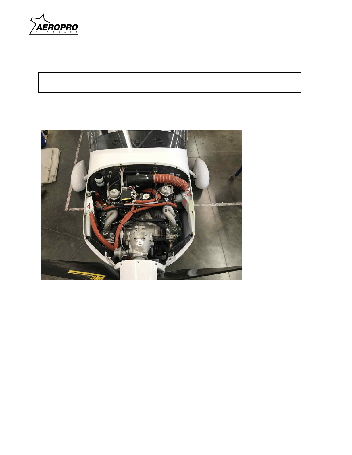
Figure 2-1 - Rotax 912ULS engine installation
1. Controls lever for carburetor heat
2. Clip for elastic air tube
3. Holder for oil cooler –one screw M5
4. Oil cooler
Note
Recommended tire pressures should be maintained. Especially in cold weather,
remember that any drop in temperature of the air inside a tire causes a
corresponding drop in air pressure.
Maintenance Manual
AEROPRO CZ
2-6
Maintenance Manual
March 21, 2020
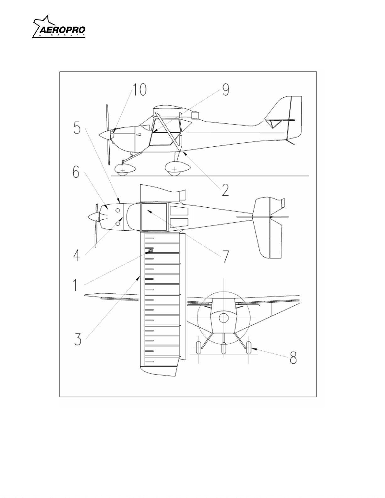
Figure 2-2

Maintenance Manual
AEROPRO CZ
2-7
Maintenance Manual
March 21, 2020
Figure 2-2
Daily
1 Fuel tank filler
Service after each flight. Keep full to reduce the possibilty of condensation in the fuel
tank. Refer to paragraph 2.13.
2 Fuel tank sump drain
Drain off sufficient amount to test for water or sediment contamination
before first flight of the day.
3 Pitot port
Check for damage, alignment and blockages before first flight of the day.
4 Induction air filter
Inspect and service regularly, give extra consideration when in dusty conditions.
Refer to paragraph 2.16 for details.
5 Oil dipstick and oil filler cap
Check oil during pre-flight. Add oil if necessary. Check base of cap for water
contamination. Refer to paragraph 2.15 for details
10 Engine cooling system
Check water level on preflight. Add specified coolant as required. Refer to the POH
and latest engine manufacturer's manual for details.
First 25 hours
6 Engine oil system
Drain and refill Oil with recommended engine oil grade, replace oil filter.
100 hours
4 Induction air filter
Clean filter per paragraph 2.16, replace as required.
7 BatteryCheck for correct voltage level. Charge or replace if required. Refer to paragraph
2.17 for details.
8 Tires Maintain correct tire inflation as listed in figure 1-1. Also refer to paragraph 2.18 for
details.
200 hours
9 Brake master cylinder
Check fluid level and refill as required with DOT 4 automobile brake fluid. Refer to
paragraph 2.19 for details.
2 Fuel tank sump drain
Drain sufficient amount to check for trances of water or sediment,
refer to paragraph 2.14 for details.
2.19 Hydraulic brake system
Check brake master cylinder and refill with correct grade of brake fluid. To refill, DOT 4
automobile brake fluid is required, as specified in the inspection chart, and no aircraft hydraulic fluid
should ever be used. Bleed the brake system to remove entrapped air whenever there is a spongy
response to the brake lever. Refer to paragraph 5.40 for filling and bleeding the brake system.
Other manuals for CZ A240
1
This manual suits for next models
1
Other Aeropro Aircraft manuals


