Thoma Modelltechnik ORBIS 20'' User manual
Installation and Operating
Manual
for the ORBIS 20’’
self-launch-system
2020 / 08
www.dr-martin-thoma.com
rbis
20‘‘

Page 2
Content
Preface to this installation and operating manual .....................................................................3
1. Installation instruction........................................................................................................4
1.1. Legend.........................................................................................................................4
1.2. Verify spatial requirements ..........................................................................................6
1.3. Determining the distance I...........................................................................................6
1.4. Cut-back of the rear wing spar.....................................................................................6
1.5. Cast for a fuselage cover.............................................................................................7
1.6. Cut out the fuselage hatches.......................................................................................7
1.7. Fuselage hatch hinges.................................................................................................8
1.8. Limit stop for the fuselage hatches..............................................................................9
1.9. Hooks for the flap springs............................................................................................9
1.10. Birch plywood support for the aluminium-support-frame ........................................10
1.11. Installation of the energy chain...............................................................................11
1.12. Cabling for operation..............................................................................................12
1.13. Installation of the brushless motor..........................................................................12
1.14. Mounting of the prop mechanism ...........................................................................12
1.15. Installation of a fuselage cover...............................................................................13
1.16. Installation of springs and a piece of wood on the left fuselage hatch....................14
1.17. Installation of a wheel cover...................................................................................14
2. Warnings .........................................................................................................................16
2.1. General Attention.......................................................................................................16
2.2. Warnings and safety instructions...............................................................................16
2.3. Disclaim of liability and damage.................................................................................18
3. Programming and Operation ...........................................................................................19
3.1. Introduction to the programming................................................................................19
3.2. Programming of the radio transmitter ........................................................................19
3.3. Programming of the receiver .....................................................................................20
3.4. Installation and adjustment of the Jeti MEZON 135 Opto controller ..........................20
3.5. Introduction to the Dirk Merbold controller.................................................................22
3.6. Programming of the Dirk Merbold controller..............................................................22
3.7. Operation procedure..................................................................................................26
4. Maintenance....................................................................................................................30
4.1. Prop mechanism and motor bell................................................................................30
4.2. Self-launch-system....................................................................................................32
5. Warranty..........................................................................................................................33
Page 3
Preface to this installation and operating manual
This manual must be read carefully before installing or operating the self-launch-system ORBIS. The
chapters will cover the following topics:
1. Installation: The first chapter takes you through the installation step by step and describes how to
cut the fuselage opening and the install the fuselage covers, where to position the support-frames.
2. Warnings: Read the warnings carefully before operating the ORBIS. Do not forget that you are
operating propeller blades with up to 3.600 Watts!
3. Programming and Operating Instructions: The programming of the Dirk Merbold Controller and
the operating of the ORBIS.
4. Maintenance: Necessary maintenance work on the ORBIS.
5. Warranty: The document ends with the warranty conditions.
Please pay special attention to the text marked with the following symbols:
Important warnings and information for operation security
Important information
Please send us your comments or suggestions for improvement of this manual or the ORBIS to:
info@dr-martin-thoma.com
Your helpful suggestions have lead to this improved version of the ORBIS 20!
Page 4
1. Installation instruction
1.1. Legend
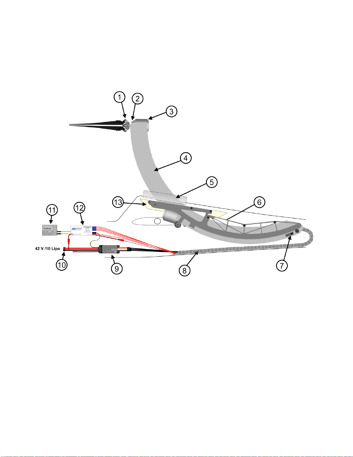
The figure below shows the different components of the self-launch-system ORBIS. This installation
instruction refers to these components.
Graphic 1.1.1. Legend for the ORBIS overview
1. Prop mechanism.
2. Tilt plate.
3. Brushless Strecker motor.
4. Full carbon-SLS-support arms
5. Fuselage cover
6. Aluminium-support-frame.
7. Micro switches to control the extension and retraction.
8. Energy chain.
9. Brushless controller Jeti MEZON 135 Opto (10 Lipo).
10. Power supply for the brushless controller Jeti MEZON 135 Opto and for the gear motor via the
Dirk Merbold controller.
11. RC-receiver.
12. Dirk Merbold controller.
13. Birch ply-wood support.

Page 5
Graphic 1.1.2. Legend for the lower ORBIS area
14. Gearmotor.
15. Turning- servo.
16. Micro switch for safety function: Important to prevent motor starting inside the fuselage.
The micro switch will be activated only when the ORBIS is completely extracted and the tilt-servo /
prop mechanism is in flight position.
Connected via female connector 8 on the Dirk Merbold controller.
17. Micro switch for the retraction activation of the gear motor.
Connected via female connector 7 on the Dirk Merbold controller.
18. Micro switch for the extension deactivation of the gear motor.
Connected via plug 6 on the Dirk Merbold controller.
19. Micro switch for the retraction deactivation of the gear motor.
Connected via female connector 5 on the Dirk Merbold controller.
Aside is a second micro switch to cut-off the power supply of the tilt-servo when the ORBIS is fully
retracted.

Page 6
1.2. Verify spatial requirements
Before you begin with the installation you have to verify the spatial requirements of the ORBIS20.
In a distance of 600 mm from the rear edge of the cockpit canopy the diameter of the fuselage must
be at least 105 mm (see graphic 1.2.1). If the diameter is between 120 mm and 105 mm you have to
attempt to insert the ORBIS into the fuselage to verify if you have enough room.
Graphic 1.2.1. Spatial requirements for the ORBIS 20’’.
1.3. Determining the distance I
The distance from the rear edge of the cockpit canopy to the front edge of the fuselage opening (see
graphic 1.2.1.-distance I) should be between 40 mm and 200 mm. With a very narrow fuselage this
distance may have to be diminished down to 10 mm. When you have determined the value for the
distance I, double-check the spatial requirements.
1.4. Cut-back of the rear wing spar
Because of spatial requirements the rear wing spar has to be cut-back centric over a length of 95 mm.
The remaining wing spars have to be reinforced with a glass fibre epoxy resin.
Graphic 1.4.1 Cut-back of the rear wing spar
Page 7
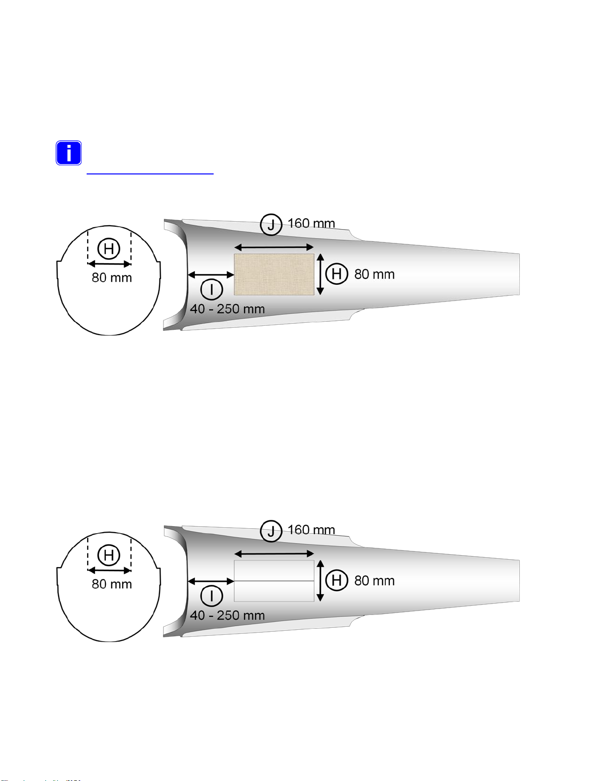
1.5. Cast for a fuselage cover
One special feature of the ORBIS is that you can attach a cover between the two carbon arm
supports, which covers the fuselage opening in the extended position. To make this fuselage cover
you must make a cast in the range of the fuselage flaps. Please make a second cover for
replacement. Put a thin plastic foil over the fuselage and laminate at least four to five glass fibre layers
with epoxy resin in the minimum size of J 160 mm x H 80 mm.
A glossy white universal sized cover can also be ordered on the website:
(www.dr-martin-thoma.com)
Graphic 1.5.1 Cast for a fuselage cover
1.6. Cut out the fuselage hatches
Mark the cut-out for the two fuselage hatches with a pencil. The hatches are divided along the centre
of the fuselage. Please keep in mind that the upper fuselage joint does not necessarily represent the
actual centre of the fuselage. Measure the two fuselage hatches according to graphic 1.6.1, where the
length of the fuselage hatches J is 160 mm and the width H is 80 mm. The fuselage opening must
have a width of 80 mm. Since the hatches are curved, they have a slightly larger width. Measure the
width from the top with a calliper gauge. Cut out the fuselage hatches with an oscillating 0,4 mm saw
or second best take a sharp knife or a Dremel using a thin cutting wheel. Use straight metal rail
guidance and fasten it with screw clamps.
Graphic 1.6.1 Cut out the fuselage hatches

Page 8
1.7. Fuselage hatch hinges
Attach four brass tubes with a length of 20 mm (2.0 mm outer diameter / 1.1 mm inside diameter )
with superglue on the inside of the fuselage flaps as shown in the figure below.
Do not use larger tubes! Otherwise the ORBIS cannot extend through the opening!
Graphic 1.7.1 Attachment of Fuselage hatch hinges
Then a 1 mm spring steel wire of 35 mm length is glued into both front brass tubes with superglue.
(see graphic 1.7.2 - 22).
Graphic 1.7.2 Attachment of spring steel wire
Four brass tubes (2,0 mm / 1,1 mm) (see graphic 1.7.3 -23) with a length of 20 mm are mounted
inside the fuselage with superglue. It is recommended to attach both flaps with PVC tape before gluing
in order to adjust the position. The curved spring steel wires in the rear brass tubes have to be
removable but must not slip out of the tube. Therefore the steel wire should be broadened a bit with a
hammer so that it jams in the brass tube of the flap.
Graphic 1.7.3 Attachment of brass tubes
After attaching the brass tubes with superglue take epoxy resin and glass fibre in order attach
everything firmly.

Page 9
1.8. Limit stop for the fuselage hatches
In order to have a limit stop for the fuselage hatches you attach a glass fibre plate on the inside of the
fuselage.
Graphic 1.8.1. Attachment of limit stop for the fuselage hatches
After attaching the limit stops with superglue take epoxy resin and glass fibre in order attach
everything firmly.
1.9. Hooks for the flap springs
A hook is needed on each hatch to attach two springs that close the flaps in the retracted position.
Attach with epoxy resin and fibre material the two metal hooks out of 1.5 mm spring steel wire on the
fuselage hatches. It is advisable to bend the lower end around to increase the adhesive surface. Make
these hooks very flat, so that the motor cables do not get entangled in the hooks.
Thus jamming the flaps when opening, the attachment of a gap cover with super glue and then with
epoxy is recommended (see chart 1.8.1 -26). This is especially necessary if the trunk flap is made of a
softer material. Otherwise, the body flaps could bend up slightly during the opening and get stuck.
Graphic 1.9.1. Attachment of the hooks for the flap springs
Page 10
1.10. Birch plywood support for the aluminium-support-frame
Two 6 mm thick front birch plywood supports for the aluminium support frame are now adapted
according to graphic 1.10.1. It is recommended to adjust a cardboard piece first in order to find the
right fuselage form for the upper edge. The upper edge must be inclined in order to become gap free
to the fuselage (see graphic 1.10.3). Attach a 20 mm M2 screw into both plywood supports from below
(see graphic 1.10.1 - 28) and screw it in for 10 mm. Cut off the head. This screw will later on hold the
spring for the flaps.
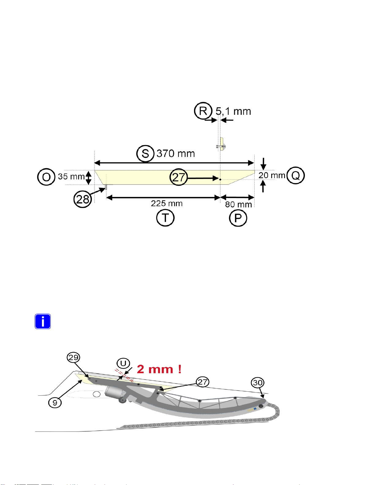
Graphic 1.10.1. Cutting out the left birch plywood support for the aluminium-support-frame
At the marked position 27 (see graphic 1.10.1 - 27) a 4 mm hole is drilled and the delivered M4
cylinder head screw is inserted and well attached with epoxy resin and fibre material. Between the
plywood support and the cylinder head a distance of 5,1 mm must remain (see graphic 1.10.1 –R) so
that the aluminium-support-frame can be inserted.
Push the aluminium-support-frame via the canopy opening into the fuselage. The back part of the
aluminium-support-frame should have only a few millimetres of distance between the upper fuselages
border (see graphic 1.10.2 -29).
The rear edge of the full carbon-SLS-support arms must have a distance of 2 mm (1.10.2 - U)
between the rear edge of the fuselage opening. Not more and not less.
In the front section of the aluminium-support-frame are two holes for the attachment of with two M4
imbus screws (see graphic 1.10.2 -29). Adjust the aluminium-support-frame in the desired position and
mark the spot 27 on both plywood supports.
Graphic 1.10.2 Adjustment of the installation position of the ORBIS.

Page 11
Drill a 6 mm hole on the position 29. Insert a drive-in M4 nut into the plywood supports. Attach the
aluminium-support-frame onto the plywood supports by screwing in the M4 imbus screws. Turn the
fuselage upside down and carefully adjust the desired position. Make sure that the fuselage opening is
at the correct position so that the ORBIS can extract out of this opening. Attach the plywood supports
with thickened (thixotroped) epoxy resin and fibre material on the grinded fuselage side (see graphic
1.10.3 -31). The M4 cylinder head screws (see graphic 1.10.2 - 27) are also well attached with epoxy
resin and fibre material.
Graphic 1.10.3. Cross section of the fuselage upside down with the inserted aluminium
support frame
1.11. Installation of the energy chain
The attachment position of the energy chain depends upon the fuselage size.
With spacious fuselages (see graphic 1.2.1 –C) with the fuselage diameter C bigger than 12 cm a
fastening element can be attached in the lower section of the fuselage ( see graphic 1.11.1 –32 ). Use
a cable strap to attach the last element of the energy chain.
Graphic 1.11.1. Fastening of the energy chain in fuselages

Page 12
1.12. Cabling for operation
In the condition as supplied to the customer the ORBIS is already wired and all connectors are joined.
It is only necessary to plug in the receiver, the brushless controller (Jeti MEZON 135 Opto) and the
lipo. Anyhow the entire cabling is shown in graphic 1.12.1 in case that an element has to be
exchanged.
Graphic 1.12.-1 Cabling of the ORBIS for operation
The female connectors coming out of the energy chain are numbered:
Connector 1: Servo cable for the tilt function
On the socket 2 the Jeti MEZON 135 Opto is connected
Connector 5: Connected to micro switch for the retraction deactivation of the gear motor.
Connector 6: Connected to micro switch for the extension deactivation of the gear motor.
Connector 7: Connected to micro switch for the retraction activation of the gear motor
Connector 8: Connected to safety micro switch for the possible activation of the brushless motor
1.13. Installation of the brushless motor
When delivered, the Strecker Brushless Motor is already attached to the ORBIS. If replacement of the
engine should be necessary, please note the following. The brushless motor is attached on the rotary
plate with three M4 TORX countersunk screws of 14mm length. The motor cable must be routed
through the CFK support and the energy chain.
1.14. Mounting of the prop mechanism
The prop mechanism can be mounted by tightening both headless hexagon screws. The screws have
to be positioned at both flat areas of the motor shaft. (see graphic 1.15.1 –33). Only this way the prop
mechanism will hold on the motor shaft. The imbus screws are secured each with an additional

Page 13
hexagon screw, so that the propmechanism will not loosen itself through vibration. This is the state in
which the ORBIS is delivered.
Verify the fixing of the prop mechanism by trying to turn the prop mechanism while
holding the motor crankcase.
Graphic 1.15.1. Mounting of the prop mechanism
Pay attention to the warnings for the prop mechanism in chapter 3.
1.15. Installation of a fuselage cover
The cast that was made in section 1.5. is now adapted to the form below. Be aware that you have to
be able to extend and retract the ORBIS to find the right position and form for the cover. The front
edge (1.16.1.-36 red line) of the cover depends on the form of the fuselage. If the fuselage is narrow
the cover must be smaller. Looking from the side the backrim of the cover (1.16.1.-37) may not
protrude the backside of the support arms.
Graphic 1.16.1. Installation of a fuselage cover
Consider the curvature of the cover since the figure above is a top view. Do not glue the cover
immediately between the SLS support arms. Firstly attach the cover with adhesive tape and verify that
the cover does not touch the fuselage wall or the levers of the end switches while the SLS is
retracting.

Page 14
The cover must not collide with any parts in the fuselage. In the extended position the cover has to be
flush with the rest of the fuselage wall. If the cover fits and has the correct form than attach it to the
SLS support arms with gel-superglue on the lower side of the cover.
Pay attention that the rear edge of the cover (see graphic 1.15.1 - 35) must flush with
the rear edge of the support arms. If the cover is going beyond the edge, the ORBIS cannot
extend nor retract.
1.16. Installation of springs and a piece of wood on the left fuselage hatch
Attach the spring on the M2 screw and hook the spring into the hook on the fuselage hatch (1.17.1 –
36).
Graphic 1.17.1.Installation of springs on the fuselage hatches and a piece of wood on the
left fuselage hatch
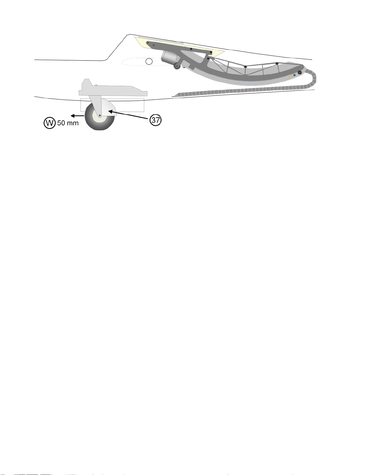
1.17. Installation of a wheel cover
It is recommended to shift the main wheel for 5 cm to the fuselage nose (see graphic 1.18.1 –W). This
will diminish the tendency of the fuselage to fall on the nose when performing a ground take-off. The
wheel of the landing gear is to be provided with a wheel cover (see graphic 1.18.1 –40). FEMA offers
such wheel covers. This is to avoid getting dirt inside the fuselage.
The interior of the fuselage and the ORBIS must be protected against any
contamination.
Page 15
Graphic 1.18.1. Positioning of the main wheel and installation of a wheel cover

Page 16
2. Warnings
2.1. General Attention
Before you operate a model airplane with motor power, you must be informed of the legal regulations
in your country. A model airplane may legally be considered an aircraft and is subject to appropriate
laws, which must be complied with.
All models / modellers need to be insured. Check out insurance offerings of your
national model organization. Never operate a model without insurance protection!
Technical disturbances e.g. radio interferences are an incalculable risk and pilots are obliged to take
all steps to avoid the possible damages. The minimum distance to populated areas, in order to ensure
security for people, animals and buildings, must be at least 1.5 km. Keep safe distance from power
lines. Do not fly the model in bad weather with low clouds or fog. Never fly directly into the sun. You
could lose eye-contact with the model. In order to avoid collisions, you must land your model
immediately, if a manned airplane approaches. The operation of a model with a self-launch-system
under the influence of alcohol, drugs, medicines, etc. is absolutely forbidden. Operate only with best
physical and mental condition. This is valid both for the operator and for its aides.
2.2. Warnings and safety instructions
General warnings
The operation of a self-launch-system can be very dangerous. The inappropriate operation of such a
system, which transfers up to 3,6 KW power to the propellers, can cause substantial personal injury.
This is a complex technology, which may be operated only by experienced model airplane pilots with
at least 18 years of age. The operation of the self-launch-system requires a check list before each
start and regular maintenance. The installation and operation of the self-launch-system may only be
done according to these instructions. Before the launch of a model with this system you must check
all functions and all rudders as well as the radio control range. Beyond that the instructions of the radio
control are to be followed.
Clearance distance
People or animals must keep the following minimum distance to the model airplane with a running
motor: - in front of the motor 10 m
- to each side of the model 15 m
- behind the motor 1 m
Always hold the model at the rear end of the fuselage when you want to test the motor. Never hold the
model at the front of the fuselage or from the side. These areas are in the danger zone.

Page 17
Range of application
The self-launch-system was solely developed for roll off ground by its own motor power. Other launch
techniques are prohibited, in particular hand launching of the model airplane while the motor is
running. This self-launch-system was solely designed for unmanned model airplanes. Do not use it for
any other purpose, in particular for any manned aircraft.
Prop mechanism
The tight mounting of the prop mechanism (two hexagon socket screws, M8 nuts ) and the motor
(three M3 screws ) must be checked before each launch. All M3 nuts on the prop mechanism have to
secured with superglue. Otherwise the prop mechanism or motor can disassemble and injure people.
From time to time you should clean the propellers with a moist piece of cloth.
Vibrations
Should vibrations occur during operation, you will have to balance the prop mechanism and the motor
bell again. The ORBIS may not be operated with vibration under any circumstances, otherwise this
may cause severe damage. If the vibration can not be eliminated, the ORBIS must be sent to the
Thoma Modelltechnik for maintenance.
Propellers
The 20 x 13 '' Freudenthaler propellers are specially designed and reinforced for the ORBIS. Only use
these propellers which can be ordered on the website www.dr-martin-thoma.com. Verify if the
propellers are undamaged before each take-off. Even the slightest damages on the propellers can
cause severe damages to your body if parts of the propeller are released. The entire prop
mechanism must be balanced out after an exchange of the propellers (see chapter 4 maintenance ).
Clean the propellers with a moist cloth from time to time to remove e.g. residue of insects.
Foreign parts
Any deviations from these instructions, like the use of other parts or materials and changes in the
ORBIS construction, affect the functionality of the system and must be avoided under all
circumstances.
Brushless controller
Use only the brushless Jeti MEZON 135 Opto controller. This brushless controller is well established
and harmonizes with the safety switch of the self-launch-system! Other brushless controllers could
catch fire in the airplane and destroy your model.
Dirk Merbold controller
The ORBIS may only be operated with the controller of Dirk Merbold and the Thoma firmware version.
The controller must be connected and programmed according to these instructions. Only the controller
of Dirk Merbold permits a control over a 3-way-switch and thus provides the necessary security. In
addition the controller accelerates the motor in the automatic modus very slowly thus preventing
damages to the prop mechanism.
Page 18
Operating
The motor must never be started if the self-launch-system is not completely extended. Although the
self-launch-system has a safety switch, it is possible that this switch can be damaged. This would
allow the motor to start even if the SLS is not completely extended. The starting of the motor in the
fuselage would cause severe damage. Therefore it must always be verified by eye-contact before
starting the motor (3-way-switch from centre to the front position) that the ORBIS is completely
extended and that the propellers are heading in flight direction. Before the ORBIS is retracted it is to
be verified by eye-contact that the propellers have come to a stop and pointing in the flight direction.
Indoor operating
Never let the propellers run with full power indoors. Objects are hurled by the enormous air turbulence
and could come into the propellers.
Foreign objects
Never leave foreign objects (e.g. pieces of cloth, screws, nuts) in the fuselage. This can lead to
malfunctioning.
Dirt protection
Protect the self-launch-system from dirt, rain and moisture. The prop mechanism is sensitive to dirt.
Water might damage the electronic components. The wheel of the landing gear must have a wheel
cover!
2.3. Disclaim of liability and damage
The adherence to these installation, operating and maintenance instructions in connection with the
model and the self-launch-system can not be supervised by Thoma Modelltechnik UG (limited liability).
Therefore Thoma Modelltechnik UG (limited liability) does not accept any liability for loss, damages or
costs, which may result from the incorrect operation, from incorrect behaviour and/or in any way
coherently with the aforementioned.
The liability of the Thoma Modelltechnik UG (limited liability) for damages caused by the self-launch-
system (including personal injuries, death, damage to buildings as well as damage by turnover or
trading loss, by business interruption or other indirect or direct damages) is excluded, as far as
German law does not regulate otherwise.
The liability is limited in all cases to the amount you paid for the self-launch-system.
The model pilot takes the entire responsibility while operating the self-launch-system.
You affirm that Thoma Modelltechnik UG (limited liability) cannot supervise the adherence to
these instructions concerning installation, operation, employment of airplane motor and
employment of the radio control.
On the part of Thoma model technology UG (limited liability) neither promises, contract arrangements,
warranties nor other agreements were made to persons or companies concerning the functionality and
the operation of the model. The operators rely on their own expertise and judgement with the
acquisition of a model and/or this self-launch-system.
German law is applicable.

Page 19
3. Programming and Operation
3.1. Introduction to the programming
The ORBIS has four different operating modes. You must choose one and program this mode into the
Dirk Merbold controller.
Operating Mode 1 A: ‘Speed Automatic On’and ‘tow release off’ on the Merbold controller.
This is the default and recommended mode for several reasons:
- The ‘Speed Automatic On’ mode will always make sure that you have the right acceleration
rate and will give you also the programmable power for ground take off.
- You will mainly fly with full throttle and thereby disburden the Jeti MEZON 135 Opto brushless
controller.
- The ‘tow release off’ mode gives you the opportunity to check the ORBIS in the extended
position without the motor starting to run.
Operating Mode 1 B: ‘Speed Automatic Off’and ‘tow release off’ on the Merbold Controller.
Operating Mode 2 A: ‘Speed Automatic On’and ‘tow release on’ on the Merbold Controller.
Operating Mode 2 B: ‘Speed Automatic Off’and ‘tow release on’ on the Merbold Controller.
3.2. Programming of the radio transmitter
For all operation modes the ORBIS needs a 3-way-switch which is assigned to a separate channel
on the radio transmitter. In the ‘‘Speed Automatic On’ you will actually only need the 3-way-switch to
control the entire ORBIS.
The 3-way-switch has pre-defined values for each switch position.
These values are reached, when the 3-way-switch switches the appropriate channel to the following
servo positions:
- 100% with position 1 (back) 1100 ms impulse length
0% with position 2 (centre) 1500 ms impulse length
+100% with position 3 (in front) 1900 ms impulse length
Important note for Jeti systems
Please make the servo pulse length of the Jetisystem is set to 20ms. A smaller or larger pulse length
may results in malfunction of the Merbold controller.
In the ‘Speed Automatic Off’ mode you will need a second continuous channel for the throttle
signal.
Page 20
The three defined operating settings in the ‘tow release off’ modus are:
•Position 1 (back): ORBIS retracted & motor off for gliding.
•Position 2 (centre): ORBIS extended & motor off .
•Position 3 (in front): ORBIS extended & motor slowly accelerating in the ‘Automatic
throttle control’ operation mode or ready for the manual throttle signal.
The three defined operating settings in the ‘tow release on’ modus are:
•Position 1 (back): Tow release locked & ORBIS retracted & motor off for gliding.
•Position 2 (centre): Tow release unlocked & v retracted & motor off for gliding.
•Position 3 (in front): ORBIS extended & motor on for the motorized climb or ready for
the manual throttle signal after extension.
The three operating conditions of the 3-way-switch must correspond to certain servo positions, since
the Merbold controller switches on two predefined signal values:
•Switch from position 1 to position 2 at 1300 ms receiver pulse length.
•Switch from position 2 to position 3 at 1700 ms receiver pulse length.
3.3. Programming of the receiver
Important note for Jeti systems
Please make the servo pulse length of the Jetisystem is set to 20ms. A smaller or larger pulse length
may results in malfunction of the Merbold controller.
The fail-safe adjustment has to be the following:
The receiver fail-safe adjustment for the 3-way-switch channel must be put on ‚hold the last
valid signal’ on the receiver. This assures that the last valid operation condition of the ORBIS and
that no unexpected behaviour of the ORBIS happens.
The receiver fail-safe adjustment for the elevator signal channel must be also put on ‚hold the last
valid signal’ on the receiver. This assures that the last valid signal for the elevator remains. This is
important when the ORBIS is running because you will need a different elevator adjustment.
The receiver fail-safe adjustment for the flaps and retract channel must be also put on ‚hold the last
valid signal’ on the receiver.
The side rudder and the ailerons must fail safe in neutral position.
3.4. Installation and adjustment of the Jeti MEZON 135 Opto controller
The Jeti MEZON 135 Opto controller is always connected to the male connector 2 of the
Merbold Controller. This is also the case when you want to use the ‘Speed Automatic Off’
This manual suits for next models
1
Table of contents


