Aeropro ST64X User manual
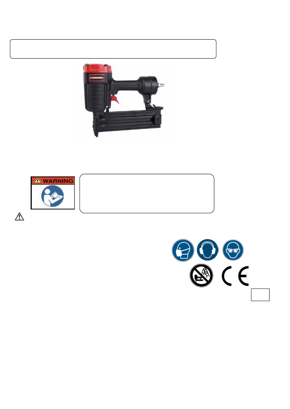
Air Nailer –Concrete nailer
Model No.:ST64X
Residual risks
Even when the tool is used as prescribed it is not possible to eliminate all residual risk factors. The following
hazards may arise in connection with the tool’s construction and design:
Damage to lungs if an effective dust mask is not worn.
Damage to hearing if effective hearing protection is not worn.
Health defects resulting from vibration emission if the power
tool is being used over longer period of time or not adequately
managed and properly maintained.
Wear eye protection.
Content
1 Technical data 2.7 Actuating systems
1.1 Fastener 3 Compressed air system
1.2 Accessories 4 Preparing the tool for use
1.3 Description/Features 4.1 Preparing a tool for first operation
1.4 Location of Parts 4.2 Connection to the Compressed air system
2 Special references 4.3 Filling the magazine
2.1 Regulations 4.4 Handling the tool
2.2 Noise emission 5. Maintenance
2.3 information on mechanical impact (vibration) 6 Troubleshooting
2.4 Safety of fastener driving tool 7 explode drawing
2.5 Safety at work 8 Spare parts list
2.6 Triggering devices
2018
OPERATING INSTRUCTIONS FOR FASTENER DRIVING TOOLS
OPERATED BY COMPRESSED AIR
IMPORTANT:
Read all safety rules and operating
Instructions carefully before first use it.
Keep this Manual for future reference.
1 Technical data
Type of tool ………………………………………………………………………………….… ST64X
Outline dimension……………………………………………………………….……90*275*355mm
Weight (without fasteners)…………………………………………………..……... 7.27Lbs (3.3kg)
Required pressure……………………………………………………………….80-110Psi (5.5-8Bar)
Max. pressure……………………………………………………………………….…..120Psi(8.3Bar)
Recommended lubricant………………………………………………….…….white mineral oil 10#
1.1 Fastener
Fastener size: Ga14(Φ2.2)
Nail length: 18-64mm (3/4”-2-1/2”)
Magazine capacity: 70pcs
1.2 Accessories
Hexagon Key
Lubricant
Operating instruction
1.3 Description/Features
This T-nailer is excellent for wood to concrete steel applications.with lightweight die-cast housing maximizes
productivity by reducing operator fatigue,shoots 14 gauge T-nails from 3/4”(18mm) to 2-1/2”(64mm) long.
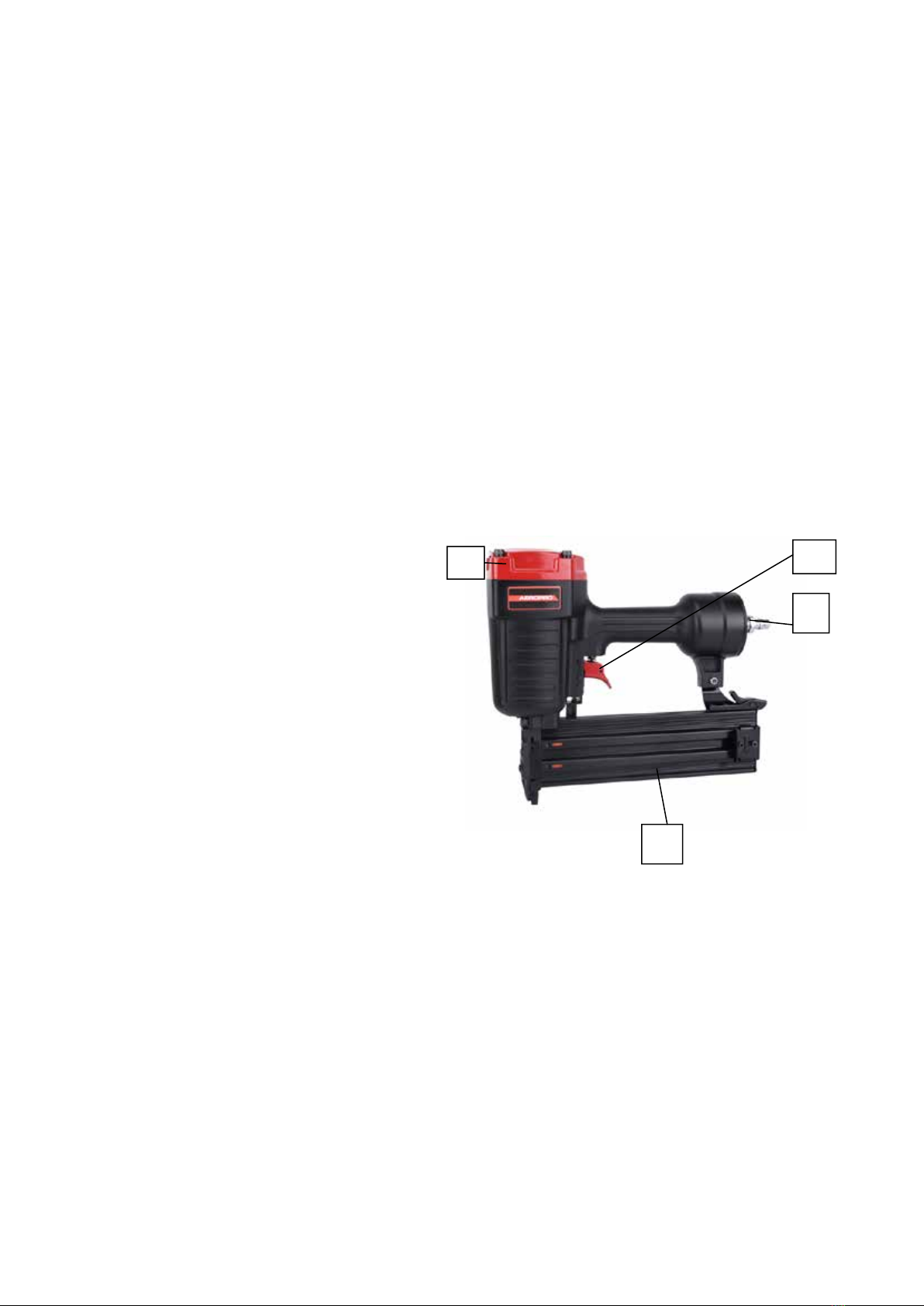
1.4 locations of Parts (see Figure 1)
A-Magazine
B-Trigger
C-Exhaust Vent
D- Air Quick Coupler
2 Special references
2.1 Instructions
The following standard is applicable to fastener driving tools; EN792-13:2000+A1:2008”Hand-held non-electric power
tools-safety requirements –Part 13: Fastener driving tools”.
This standard requires that
-only those fasteners which are specified in the operating instructions (see TECHNICAL DATA)shall be used in
fastener driving tools. The fastener driving tool and the fasteners specified in the operating instructions are to be
considered as one unit safety system;
-quick action couplings shall be used for connection to the compressed air system and the non-sealable nipple
must be fitted at the tool in such a way that no compressed air remains in the tool after disconnection;
-oxygen or combustible gases shall not be used as an energy source for compressed air operated fastener driving
tools;
-fastener driving tools shall only be connected to an air-supply where the maximum allowable pressure of the tool
cannot be exceeded by more than 10%;in the case of higher pressure ,a pressure reducing valve which includes a
downstream safety valve shall be built into the compressed air supply;
-only spare parts specified by the manufacturer or his authorized representative shall be used in the repair of
fastener driving tools;
-repairs shall be carried out only by the manufacturers authorized agents or by other experts, having due regard to
D
C
B
A

Fig 2
the information given in the operating instructions.
-stands for mounting the fastener driving tools to a support, for example to a work table, shall be designed and
constructed by the stand manufacturer in such a way that the fastener driving tools can be safely fixed for the
intended use, thus for example avoiding damage, distortion, displacement.
Special fields of application for the fastener driving tool may require the observance of additional provisions and
regulations.
-only the main energy and lubricants listed in the operating instructions may be used:
-fastener driving tools marked with an inverted equilateral triangle standing on one point may only be used with an
effective safety yoke;
-for the maintenance of fastener driving tools, only spare parts specified by the manufacturer or his authorized
representative shall be used;
-repairs shall be carried out only by agents authorized by the manufacturer or by other specialists, having due
regard to the information given in the operating instructions;
-NOTE: Specialists are those who, as a result by professional training or experience, have sufficient expertise
in the field of fastener driving tools and sufficient familiarity with relevant govemmental industrial protection
provisions, accident prevention regulations, directives and generally recognized technical regulations(e.g.
CEN-and CENELEC-standards),to be able to assess the safe working condition of fastener driving tools.
2.2 Noise emission
The characteristic noise values for the fastener driving tool have been determined in accordance with EN12549:1999 and
EN ISO4871”Acoustics-Noise test code for fastener driving tools-Engineering method”(see Technical Data).
These values are tool-related characteristic values and do not represent the noise development at the point of use. Noise
development at the point of use will for example depend on the working environment, the work piece, the work piece
support and the number of driving operations, etc.
2.3 Information on mechanical impact (vibration)
The characteristic vibration values for the fastener driving tool have been determined in accordance with ISO
8662-11:1999 and EN 12096 –Measurement of vibration in hand-held power tools –Part 11:Fastener driving tools(see
Technical Data).
This value is a tool-related characteristic value and does not represent the influence to the hand-arm-system when using
the tool. An influence to the hand-arm-system when using the tool will for example depend on the gripping force, the
contact pressure force, the working direction, the adjustment of energy supply, the workplace, the work piece support.
2.4 Safety of the fastener driving tool
-Check prior to each operation that the safety and triggering mechanism is functioning properly and that all nuts and
bolts are right.
-Do not carry out any alterations to the fastener driving tool without the manufactures authorization.
-Do not disassemble or make inoperative any parts of the fastener driving tool such as the safety yoke.
-Do not perform any” emergency repairs” without proper tools and equipment.
-The fastener driving tool should be serviced properly and at regular intervals in accordance with the
Manufacturer’s instructions.
-Avoid weakening or damaging the too, for example by:
punching or engraving;
modification not authorized by the manufacturer
guiding against templates made of hard material such as steel;
use the equipment as a hammer;
applying excessive force of any kind
2.5 Safety at work
Never point any operational fastener driving tool at yourself or at any other person or animals.
Hold the fastener driving tool during the work operation in such a way that no injuries can be
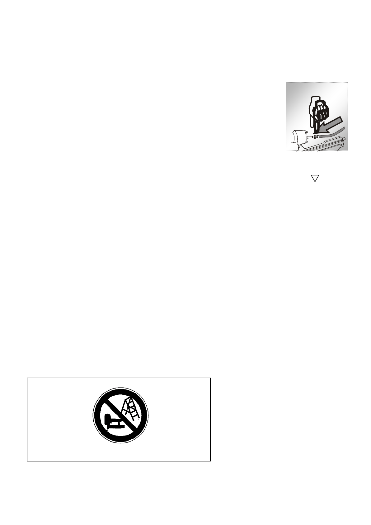
Fig 3
caused to the head or to the body in the event of possible recoil consequent upon a disruption in the energy supply or
hard areas within the workplace.(see fig 2)
Never actuate the fastener driving tool into free space. This will avoid any hazard caused by free flying fasteners and
excessive strain of the tool.
The tool shall be disconnected from the compressed air system for the purpose of transportation, especially where
ladders are used or where an unusual physical posture is adopted whilst moving (see Fig 3).
Carry the fastener driving tool at the workplace using only the handle, and never with the
trigger actuated.
Take conditions at the workplace into account. Fasteners can penetrate thin work pieces or
slip off corners and edges of workplaces, and thus put people at risk.
For personal safety, use protective equipment such ad hearing and eye protection (see fig 2)
IMPORTANT: DO NOT direct the adjustable vent hole to the operator or other person or animals
during the use.
2.6 Triggering devices
Fastener driving tools are operated by actuating the trigger using finger pressure.
In addition, fastener driving tool is fitted with a safety yoke which enables the driving operation to be carried out only after
the muzzle of the tool is pressed against a work piece, These tool are marked with an inverted triangle( ) behind the
serial number and are not permitted for use without an effective safety yoke.
2.7 Actuating systems
Depending on their purpose, fastener driving tool is fitted with actuating system of single sequential actuation and contact
actuation.
You could switch to one nail figure to choose single sequential actuation, and switch to two nail figure to choose contact
actuation.
- Single sequential actuation: An actuating system in which the trigger and the safety yoke have to be activated so the
only one single driving operation is actuated via the trigger after the muzzle of the tool has been applied to the driving
location, Thereafter further driving operations can only be performed after the trigger has been returned to the non driving
position whilst the safety yoke remains depressed.
-Contact actuation (restricted version):An actuating system in which the trigger and the safety yoke have to be actuated
for each driving operation, with the order of actuation not being specified .For repeated driving operations, it is sufficient if
either the trigger remains activated and the safety yoke is activated thereafter, or vice versa.
Fastener driving tools equipped with contact actuation must be marked with the symbol” Do not use on scaffoldings,
ladders’ (see Fig.4) and shall not be used for specific application for example:
-when changing one driving location to another involves the use of scaffoldings, stairs, ladders, or ladder alike
constructions, e.g. roof laths;
-closing boxes or crates;
-fitting transportation safety systems e.g. on vehicles and wagons.
Colours:
Red on white ground,
fastener driving tools and
ladder black
Fig. 4: Symbol” Do not use on scaffoldings, ladders”
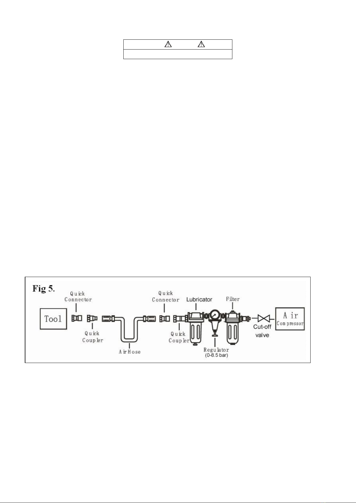
3 Compressed air system
Proper functioning of the fastener driving tool requires filtered, dry and lubricated compressed air in adequate quantities.
If the air pressure in the line system exceeds the maximum allowable of the fastener driving tool, a pressure reducing
valve followed by a downstream safety valve shall additionally be fitted in the supply line to the tool.
NOTE: When compressed air is generated by compressors, the natural moisture in the air condenses and collects
as condensed water in pressure vessels and pipelines. This condensate must be removed by water separators.
These water separators must be checked on a daily basis and if necessary drained, since corrosion can
otherwise develop in the compressed air system and in the fastener driving tool. Which serves to accelerate
wear?
The compressor plant shall be adequately dimensioned in terms of pressure output and performance (volumetric flow) for
the consumption which is to be expected. Line sections which are too small in relation to the length of the line (pipes and
hoses), as well as overloading the compressor, will result in pressure drops.
Permanently laid compressed air pipelines should have an internal diameter of at least 19 mm and a corresponding large
diameter where relatively long pipelines or multiple users are involved.
Compressed air pipelines should be laid so as to form a gradient (highest point in the direction to the compressor).Easily
accessible water separators should be installed at the lowest points.
Junctions for users should be joined to the pipelines from above,
Connecting points for fastener driving tools should be fitted with a compressed air servicing unit(filter/water
separator/oiler)directly at the junction point.
Oilers must be checked on a daily basis and if necessary topped up with the recommended grade of oil (see TECHNICAL
DATA). Where hose lengths of over 10 m are used., the oil supply for the fastener driving tool cannot be guaranteed, We
therefore recommend that 2to 5drops (depending on the loading of the fastener driving tool)of the recommended oil (see
TECHNICAL DATA) should be added via the air inlet of the tool, or an oiler attached directly to the fastener driving tool.
(see fig 5)
4 Preparing the tool for use
4.1 Preparing a tool for first time operation
Please Read and observe these Operating Instruction before using the tool. Basic safety measures should always be
strictly followed to protect against damage to the equipment and personal injury to the user or other people working in the
vicinity of operation.
4.2 Connection to the compressed air system
Ensure that the pressure supplied by the compressed air system does not exceed the maximum allowable pressure of
the fastener driving tool. Set the air pressure initially to the lower value of the recommended allowable pressure (see
TECHNICAL DATA).
Empty the magazine to prevent a fastener from being ejected at the next stage of work in the event that internal parts of
the fastener driving tool are not in the starting position following maintenance and repair work or transportation.
Connect the fastener driving tool to the compressed air supply using suitable pressure hose equipped with quick-action
WARNING
Never free-fire the tool at high pressure.

connectors.
Check for proper functioning by applying the muzzle of the fastener driving tool to a piece of wood or wooden material
and actuating the trigger once or twice.
4.3Filling the magazine
Only those fasteners specified under TECHNICAL DATA (see 1.1) may be used
When filling the magazine, hold the tool so that the muzzle is not pointing towards the operator or any other person or
animals.
4.4 Handling the tool
Pay attention to 2-Special Reference-of these operating instructions.
Having checked that the fastener driving tool is functioning correctly, apply the tool to a work piece and actuate the
trigger.
Check whether the fastener has been driven into the work piece in accordance with the requirements.
- if the fastener is protruding, increase the air pressure in increments of 0.5 bar, checking the result after each new
adjustment;
- if the fastener is driven into an excessive depth reduce the air pressure I increments of 0.5 bar until the result is
satisfactory.
You should endeavor in any event to work with the lowest possible air pressure. This will give you three significant
advantages;
1. Energy will be saved, 2. Less noise will be produced, 3. Areduction in fastener driving tool wear will be achieved.
Avoid triggering the fastener driving tool if the magazine is empty.
Any defective or improperly functioning fastener driving tool must immediately be disconnected from the compressed air
supply and passed to a specialist for inspection.
In the event of longer breaks in work or at the end of the working shift, disconnect the tool from the compressed air supply
and it is recommended to empty the magazine.
The compressed air connectors of the fastener driving tool and the hoses should be protected against contamination, the
ingress of coarse dust chips, sand etc, will result in leaks and damage to the fastener driving tool and the couplings.
5. Maintenance
Disconnect the tool from the compressor before adjusting, clearing jams, servicing &maintenance, relocating and during
non operation.
Regular lubrication, if your tool without using the in-liner automatic oilier, place 2 or 6 drops of pneumatic tool oil into
the air inlet before each work day or after 2 hours of continuous use depending in the characteristic of work piece or type
of fasteners.
Air-operated tools must be inspected periodically, and worn or broken parts must be replaced to keep the tool
operating safely and efficiently. Check and change all worn or damaged O-ring, Seals, etc. Tighten all the screws and
caps to avoid personal injury. This should be done by an expert.
Make regular inspection for free movement of trigger, spring and safety mechanism to assure safe system is complete
and functional: no loose and missing parts, no building or stocking parts.
Keep magazine and nose of tool clean and free of any dirt lint or abrasive particles.
When temperatures are below freezing, tools should be kept warm by any convenient, safe method.

6 Troubleshooting (See Table 1)
SYMPTOM
PROBLEM
SOLUTIONS
Air leak near top of tool or
in trigger area
1. O-ring in trigger valve is damaged.
2. Trigger valve head are damage.
3. Trigger valve stem, seal or O-ring are
damaged.
1. Check and replace O-ring.
2. Check and replace.
3.Check and replace trigger valve stem,
seal or O-ring
Air leak near bottom of tool.
1. Loose screws.
2. Worn or damaged O-rings or bumper.
1. Tighten screws.
2. Check and replace O-rings or bumper.
Air leak between body and
cylinder cap.
1. Loose screws.
2. Worn or damaged O-rings or seals.
1. Tighten screw.
2. Check and replace O-rings or bumper.
Blade driving fastener too
deep.
1. Worn bumper.
2. Air pressure is too high.
1. Replace bumper.
2. Adjust the air pressure.
Tool does not operate well:
can not drive fastener or
operate sluggishly.
1. Inadequate air supply.
2. Inadequate lubrication.
3. Worn or damaged O-rings or seals.
4. Exhaust port in cylinder head is blocked.
1. Verify adequate air supply.
2. Place 2 or 6 drops of oil into air inlet.
3. Check and replace O-rings or seal.
4. Replace damaged internal parts.
Tool skips fasteners.
1. Worn bumper or damaged spring.
2. Dirt in front plate.
3. Dirt or damage prevents fasteners from
moving freely in magazine.
4. Worn or dry O-ring on piston or lack of
Lubrication.
5. Cylinder covers seal leaking.
1. Replace bumper or pusher spring.
2. Clean drive channel on front plate.
3. Magazine needs to be cleaned.
4. O-ring needs to be replaced.
And lubricate.
5. Replace Sealing washer.
Tool jams.
1. Incorrect or damaged fasteners.
2. Damaged or worn driver guide.
3. Magazine or nose screw loose.
4. Magazine is dirty.
1. Change and use correct fastener.
2. Check and replace the driver.
3. Tighten the magazine.
4. Clean the magazine.

7. Explode Drawing &Spare parts list
Note: if you need spare parts of this model, please feel free to contact us or the distributor where you bought this tool. Tks
No.
K3 CODE
Description
Qty.
No.
K3 CODE
Description
Qty.
No.
K3 CODE
Description
Qty.
1
03.04.05.049
Bolt M6*35
4
24
03.04.01.048
O-ring 6.4*2
1
47
03.04.04.111-01
Safety nose
1
2
03.04.05.265
Spring Washer
6
25
03.04.29.005
Valve sleeve
1
48
03.04.08.157-01
Driver guide
1
3
Cylinder cover
1
26
03.04.01.060
O-ring 9*1.8
1
49
03.04.30.018
Insert bar
1
4
03.04.19.167
Sealing washer
1
27
03.04.01.034
O-ring 2.5*1.5
1
50
03.04.14.095
Fixed magazine
1
5
03.04.36.123
Compressed spring
1
28
03.04.34.043
Switch spring
2
51
03.04.09.035
Pusher
1
6
03.04.01.075
O-ring 13.7*2.4
1
29
03.04.15.038
Switch pole
1
52
03.04.15.107-01
Push rod
2
7
03.04.39.08.010
Head Valve
1
30
03.04.01.091
O-ring 18*2.65
1
53
03.04.36.135
Compressed spring
2
8
03.04.01.187
O-ring 56*2.65
1
31
03.04.32.056
Switch seat
1
54
03.04.18.055-02
Movable magazine
1
9
03.04.19.135
Sealing washer
1
32
03.04.36.006
Compressed spring
1
55
03.04.05.013
Bolt M4*16
2
10
03.04.19.136
Collar
1
33
03.04.01.027
O-ring 1.7*2
3
56
03.04.12.017-01
Locating seat
1
11
03.04.01.212
O-ring 73*2.65
1
34
03.04.31.056
Trigger pin
3
57
03.04.31.033-02
Shaft pin
1
12
03.04.01.185
O-ring 53*2.65
1
35
03.04.03.044-03
Trigger
1
58
03.04.24.051
Torsional spring
1
13
03.04.27.059
Cylinder
1
36
03.04.02.015
Safety spacer
1
59
03.04.10.030-01
Locating stem
1
14
03.04.01.183
O-ring 53*2
1
37
03.04.05.191
Pin 3*16
1
60
03.04.12.134-01
Fixed seat
1
15
03.04.01.166
O-ring 44.4*2.5
1
38
03.04.32.121-02
Safety seat
1
61
03.04.01.028
O-ring 1.9*1.1
1
16
03.04.39.01.066
Piston assembly
1
39
03.04.36.016
Compressed spring
1
62
03.04.05.262-03
Spring washer 4
3
17
03.04.06.053
Bumper
1
40
03.04.16.050-01
Safety yoke
1
63
03.04.05.009
Bolt M4*8
3
18
Gun body
1
41
03.04.02.065-01
Plate
1
64
03.04.05.204
Pin 4*10
1
19
03.04.06.009
Rubber washer
1
42
03.04.05.048
Bolt M6*30
2
65
03.04.05.034
Bolt M5*25
1
20
03.04.01.080
O-ring 15*2.65
1
43
03.04.05.028
Bolt M5*12
3
66
03.04.05.163-01
Nut M5
1
21
03.04.01.082
O-ring 16*1.6
1
44
03.04.13.154-01
Cover board
1
67
03.04.01.201
O-ring 63*2.65
1
22
03.04.32.105
Valve seat
1
45
03.04.05.032
Bolt M5*20
2
68
03.04.11.011-10
1
23
03.04.01.047
O-ring 6.1*1.8
1
46
03.04.05.263-03
Spring washer
3
69
Air inlet plug
1
Table of contents
Other Aeropro Nail Gun manuals


Popular Nail Gun manuals by other brands


Campbell Hausfeld
Campbell Hausfeld CHN70500 Easy setup guide

ISANTA
ISANTA Senco GT40FS operating instructions

Max
Max GS683RH-EX Operating and maintenance manual

Craftsman
Craftsman 351.181720 Operator's manual

Campbell Hausfeld
Campbell Hausfeld Finishing Nailer JB006750 operating instructions

Makita
Makita FN001G instruction manual