Aeropro 07204 User manual

16
FOR HELP OR ADVISE ON THIS PRODUCT PLEASE
CONTACT YOUR DISTRIBUTOR, OR SIP DIRECTLY
ON:
TEL: 01509500400
EMAIL: sales@sip-group.com or technical@sip-
group.com
www.sip-group.com
Please dispose of packaging for the product in a responsible
manner. It is suitable for recycling. Help to protect the
environment, take the packaging to the local amenity tip and
place into the appropriate recycling bin.
Ref: 090913
1
Composite
3” Cut Off Tool
07204
Please read and fully understand the in-
structions in this manual before operation.
Keep this manual safe for future reference

2
15
DECLARATION OF CONFORMITY
Declaration of Conformity
We
SIP (Industrial Products) Ltd
Gelders Hall Road
Shepshed
Loughborough
Leicestershire
LE12 9NH
England
As the manufacturer's authorised representative within the EC
declare that the
Composite 3” Cut Off Tool - SIP Part. No. 07204
Conforms to the requirements of the following directive(s), as indicated.
2006/42/EC Machinery Directive
Signed: …………………………………...
Mr P. Ippaso - Managing Director - SIP (Industrial Products) Ltd
Date: 06/01/2013.
And the relevant harmonised standard(s)

14
Ref. No. Description SIP Part No. Ref. No. Description SIP Part No.
1. Bolt AI05-00410 17. Back plate AI05-00426
2. Washer AI05-00411 18. Bearing AI05-00427
3. Disc 07591 19. Rubber ring AI05-00428
4. Fixed seat AI05-00413 20. Housing AI05-00429
5. Front sheath AI05-00414 21. Noise reduction nut AI05-00430
6. Disc guard AI05-00415 22. Air inlet plug AI05-00431
7. Lockage ring AI05-00416 23. Trigger AI05-00432
8. Bearing AI05-00417 24. Trigger pin AI05-00433
9. Front plate AI05-00418 25. Lockage pin AI05-00434
10. Rotor bushing AI05-00419 26. O-ring AI05-00435
11. Steel ball AI05-00420 27. O-ring AI05-00436
12. Gasket AI05-00421 28. Lockage ring spring AI05-00437
13. Rotor blade AI05-00422 29. Regulator AI05-00438
14. Rotor AI05-00423 30. O-ring AI05-00439
15. Pin AI05-00424 31. O-ring AI05-00440
16. Cylinder AI05-00425 32. Adjusting nut AI05-00441
PARTS LIST
3
Page No. Description
4. Safety Instructions
6. Contents and Accessories
7. Getting to Know Your Air Cut off tool
8. Technical Specifications
8. Guarantee
9. Operating Instructions
11. Maintenance
12. Troubleshooting
13. Exploded Drawing
14. Parts List
15. Declaration of Conformity
CONTENTS

4
SAFETY INSTRUCTIONS
IMPORTANT: Please read the following instructions carefully, failure to do so could
lead to serious personal injury and / or damage to the cut off tool.
When using your cut off tool, basic safety precautions should always be followed to
reduce the risk of personal injury and / or damage to it.
Read all of these instructions before operating the cut off tool and save this user man-
ual for future reference.
The cut off tool should not be modified or used for any application other than that for
which it was designed.
This air tool is designed to be used as a hand held, hand controlled tool for cutting
sheet metal, metal bolts / brackets and similar applications.
If you are unsure of its relative applications do not hesitate to contact us and we will
be more than happy to advise you.
Before operating the cut off tool always check no parts are broken and that no parts
are missing.
Always operate the cut off tool safely and correctly.
KNOW YOUR CUT OFF TOOL: Read and understand the owner's manual and labels
affixed to the cut off tool. Learn its applications and limitations, as well as the potential
hazards specific to it.
KEEP CHILDREN AND UNTRAINED PERSONNEL AWAY FROM THE WORK AREA: All visitors
should be kept at a safe distance from the work area; never allow untrained persons
to operate the cut off tool.
STAY ALERT: Always watch what you are doing and use common sense.
HAVE YOUR CUT OFF TOOL REPAIRED BY A QUALIFIED PERSON: The cut off tool is in ac-
cordance with the relevant safety requirements. Repairs should only be carried out by
qualified persons using original spare parts, otherwise this may result in considerable
danger to the user and void the warranty.
DANGER! Check that the cut off tool is in sound condition and good working order;
Take immediate action to repair or replace damaged parts.
DO NOT dismantle or tamper with the cut off tool, as this may be dangerous and will
invalidate the warranty.
If a problem with the cut off tool is experienced or suspected stop using it immedi-
ately and contact your distributor for repair.
Regularly inspect and lubricate the cut off tool, ensuring that it is in good working
order and condition.
Always ensure that the work area is clean and tidy, free from unrelated materials and
has adequate lighting.
Clean and stow the cut off tool correctly.
Failure to follow the warnings in this manual, may result in personal injury and/or prop-
erty damage.
DO ensure that only compressed air is used to supply the air tool.
13
EXPLODED DRAWING

12
PROBLEMS POSSIBLE CAUSES REMEDIES
Tool runs at normal speed
but struggles under load.
Motor parts worn.
Gears worn or sticking due
to lack of lubricant.
Check / have the parts checked and re-
pair / replace as necessary.
Check that the gears are well greased;
add grease where necessary.
NOTE: Heat usually indicates insufficient
grease in gears. Severe operating condi-
tions may require more frequent lubrica-
tion.
Tool runs slowly. Air flows
slightly from exhaust.
Inlet filter restricted.
Motor parts jammed with
dirt particles.
Air flow blocked by dirt.
Check air inlet filter for blockage.
Pour air tool lubricating oil into air inlet,
operate tool in short bursts quickly reversing
rotation back and forth where applicable.
Repeat above as needed. If this fails return
to service centre.
Tools will not run. Air flows
freely from exhaust.
One or more motor vanes
stuck due to material build
up.
Pour air tool lubricating oil into air inlet,
operate tool in short bursts quickly reversing
rotation back and forth where applicable.
Tap motor housing gently with plastic mal-
let.
Disconnect supply; Free motor by rotating
drive shank manually where applicable
If tool remains jammed return to service
centre.
Tool will not shut off.
‘O’ rings throttle valve dis-
lodged from seat inlet
valve.
Replace ‘O’ ring or return to service centre.
Note: Repairs should be carried out by a qualified person.
The following form lists the common operating issues with problems and solutions.
Please read the form carefully and follow it.
If any of the following symptoms occurs during your operation, stop using the tool immediately, or serious
personal injury could result. Only a qualified person or an authorised service centre should perform repairs
of the tool. Disconnect from the air supply before attempting repairs or adjustments. When replacing O-
rings etc. lubricate with air tool oil before assembly.
TROUBLESHOOTING
5
SAFETY INSTRUCTIONS….cont
The compressed air supply MUST be at a suitable regulated pressure. Pipe work, reg-
ulators, hoses, isolation valves and connection devices MUST be suitable for the in-
tended application correctly installed and maintained in good condition by a com-
petent person.
Appropriate Personal protective equipment MUST be worn and MUST be designed to
protect against all hazards created. Severe permanent injury can result from using
inappropriate or insufficient protective equipment - Eyes in particular are at risk.
Long hair MUST be tied back; loose clothing MUST NOT be worn. There is a severe risk
of these being drawn in or trapped by the moving parts of the air tool.
Open or damaged compressed air lines present a significant ‘whip’ hazard; isolate
the problem hose from the air supply and repair / replace the hose immediately.
This air tool is electrically conductive DO NOT allow it to come into contact with any
source of electrical supply.
After use wait for the air tool to STOP completely before putting it aside.
When putting the air tool aside you MUST ensure that it placed in a stable position. To
avoid inadvertent operation DO NOT place the air tool where it can be knocked or
moved accidentally either directly or by the air connection hose.
If the air tool is not required or the air supply is interrupted, disconnect the air tool
from the air supply and place in secure storage to prevent unauthorised use.
Ensure the air valve (or trigger) is in the “off” position before connecting to the air sup-
ply.
Disconnect the cut off tool from the air supply before making adjustments, changing
discs etc. and before servicing the tool.
Always keep your air tool clean and lubricated. Daily lubrication is essential to avoid
internal corrosion and possible failure.
Do not overload the tool. Allow the tool to operate at its optimum speed for maxi-
mum efficiency.
Do not increase the air pressure above the manufacturers recommended level, as
excessive pressure can cause the tool casing to split. This can also create excessive
wear on moving parts and possible failure.
Always ensure that the work-piece is firmly secured leaving both hands free to control
the cut off tool.
Always wear safety goggles or glasses during operation.
Do not wear watches, rings bracelets or loose clothing when using air tools.
Use as light weight a hose as possible from the tool to the wall or compressor cou-
pling.
In the interests of safety and possible damage to the machine/operator, always en-
sure that the cut off tool has stopped before putting it down after use.
Always ensure that the accessories such as discs are rated / designed for use with
this cut off tool as well as the required application, and are correctly and securely
fastened before connecting the tool to the air supply.
Do not carry or move the air cut off tool by its air hose.
Never allow the tool to come into contact with harsh solvents such as petrol.
6
SAFETY INSTRUCTIONS….cont
CAUTION: The warnings and cautions mentioned in this user manual can not
cover all possible conditions and situations that may occur. It must be under-
stood by the operator that common sense and caution are factors which can-
not be built into this product, but must be applied.
We recommend wearing ear protection - particularly during extended
periods of operation.
We recommend wearing a face mask or respiratory equipment when
using any air tool; particularly during drilling, sanding, grinding, sawing or
other operations likely to cause airborne particles.
Always wear approved safety goggles / glasses when using or maintain-
ing any air tool, everyday eyeglasses have only impact resistant lenses,
they are not safety glasses.
Note: If any of the above are missing or damaged, contact your distributor
immediately.
Cut Off Tool Instruction Manual Quick Coupler (Euro type)
Cutting Disc Hex Wrench Small Wrench
Small Bottle of Oil
CONTENTS AND ACCESSORIES
11
DO NOT use the tool if it is, or has parts that are worn, damaged or missing; re-
move from service and have the parts repaired / replaced using original spare
parts.
Ensure that the air tool is lubricated daily with a few drops of air tool oil dripped
into the air inlet.
Clean the air tool after each use.
Check hose and fittings for wear or damage before each use.
Drain the air tank / receiver of the compressor daily; Water in the air line will
damage the drill.
In the event that it becomes necessary to store the tool for an extended period
of time (overnight, weekend, etc.), it should receive a generous amount of lubri-
cation at that time. The tool should be run for approximately 30 seconds to en-
sure oil has been evenly distributed throughout the tool.
The tool should be stored in a clean and dry environment.
Disconnect the air tool from the air supply before changing accessories,
servicing or performing maintenance. Replace or repair damaged parts.
Use genuine parts only. Non-authorised parts may be dangerous and will
invalidate the warranty.
OPERATING THE CUT OFF TOOL
Once the disc is fitted and secure:
Connect the drill to the air supply via the air inlet (6).
Press the Trigger / Throttle Safety Lock (4) to allow the trigger / throttle (5) to be
depressed.
Press the trigger / throttle lever (5) and the cut off tool will operate.
Release the trigger / throttle (5) and the tool will stop.
Note: Never start the cut off tool with the disc touching the work-piece.
Allow the tool to reach full speed before starting the cutting (or similar)
operation.
OPERATING INSTRUCTIONS….cont
MAINTENANCE
10
CAUTION: If a filter/regulator/lubricator is not installed on the air system,
air operated tools should be lubricated at least once a day or after 2
hours work with 2 to 6 drops of oil, depending on the work environment,
directly through the male fitting in the tool housing.
An automatic in-line filter-regulator-lubricator is recommended (Fig.1) as it in-
creases tool life and keeps the tool in sustained operation. The in-line lubricator
should be regularly checked and filled with air tool oil.
Proper adjustment of the in-line lubricator is performed by placing a sheet of
paper next to the exhaust ports and holding the throttle open for approximately
30 seconds. The lubricator is properly set when a light stain of oil collects on the
paper. Excessive amounts of oil should be avoided.
In the event that it becomes necessary to store the tool for an extended period
of time (overnight, weekend, etc.), it should receive a generous amount of lubri-
cation at that time. The tool should be run for approximately 30 seconds to en-
sure oil has been evenly distributed throughout the tool. The tool should be
stored in a clean and dry environment.
It is most important that the tool be properly lubricated by keeping the air line
lubricator filled and correctly adjusted. Without proper lubrication the tool will not
work properly and parts will wear prematurely.
Use the proper lubricant in the air line lubricator. The lubricator should be of low
air flow or changing air flow type, and should be kept filled to the correct level.
Use only recommended lubricants, specially made for pneumatic applications.
Substitutes may harm the rubber compounds in the tools O-rings and other rub-
ber parts.
FITTING A DISC
Remove the old disc:
Place the supplied small wrench over the 2 flat sections on either side of the
disc retaining shaft; this is to hold the shaft in position.
Use the supplied hex. wrench to turn the cap head bolt anti-clockwise to loosen
and remove.
Remove the retaining washer and the old disc.
Fit the new disc over the shaft.
Refit the washer and secure as above, but turn the cap head bolt clockwise.
LUBRICATION
OPERATING INSTRUCTIONS….cont
7
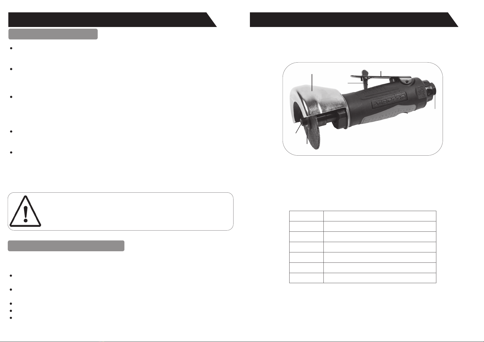
GETTING TO KNOW YOUR COMPOSITE AIR CUT OFF TOOL
Ref. No. Description
1. Disc Retaining Washer
2. Disc Retaining Bolt
3. Safety Guard
4. Trigger / Throttle Safety Lock
5. Trigger / Throttle
6. Air Inlet
1
2
3
4
5
6

8
SIP Part No. 07204
Disc Ø 3” (76.2mm)
Disc Bore 3/8” (9.52mm)
No Load Speed 18000 rpm
Average Air Consumption 4 cfm (114 l/min)
Operating Pressure 6.3 bar (90 psi)
Air Inlet 1/4” bsp
Sound Pressure (LpA) * 79.4 dB(A)
Sound Power (LwA) * 90.4 dB(A)
Vibration ** 1.67 m/s2
Guarantee:
This SIP air cut off tool is covered by a 12 month parts and labour warranty covering
failure due to manufacturers defects. This does not cover failure due to misuse or op-
erating the cut off tool outside the scope of this manual - any claims deemed to be
outside the scope of the warranty may be subject to charges Including, but not lim-
ited to parts, labour and carriage costs.
Consumables such as discs are not covered under the warranty.
Failure to lubricate your air tool will shorten its working life and reduce performance.
The warranty does not cover rusting air tools and tools that failed due to the lack of
lubrication.
Note: Proof of purchase will be required before any warranty can be hon-
oured.
TECHNICAL SPECIFICATIONS
GUARANTEE
* Measured in accordance with ISO 15744; level of uncertainty 3dB(A).
** Measured in accordance with ISO 28927-4; level of uncertainty 0.26 m/s2.
9
Ensure the air trigger / throttle (5) is not depressed before connecting to the air
supply.
You will require an air pressure of 90psi, and an air flow according to specifica-
tion.
WARNING! Ensure the air supply is clean and does not exceed 90psi while oper-
ating the cut off tool. Too high an air pressure and unclean air will shorten the
product life due to excessive wear, and may be dangerous causing damage
and/or personal injury.
Drain the air tank daily; water in the air line will damage the cut off tool.
Recommended hook-up procedure is shown in fig 1.
Line pressure should be increased to compensate for unusually long air hoses
(over 8 metres). The minimum hose diameter should be 3/8” I.D. and fittings
must have the highest flow rate that can be fitted to the tool.
Keep hose away from heat, oil and sharp edges. Check hose for wear, and
make certain that all connections are air tight secure.
This 3” cut off tool is designed with a durable lightweight composite housing. It has a
variable speed trigger / throttle for precise start-up and control, handle mounted ex-
haust to reduce noise and direct air flow away from the operators face. It is the ergo-
nomic choice for cutting operations etc.
DESCRIPTION
AIR SUPPLY
OPERATING INSTRUCTIONS
Tool
Compressor
Quick Connector Quick Connector
Quick Coupler Quick CouplerAir Hose
Regulator
Lubricator
Filter
Cut Off Valve
Fig. 1


