SawStop MB-CNS-000 User manual

SawStop®
OWNER’S MANUAL
Contractor Saw Mobile Base
Model MB-CNS-000
Lower
Raise
Never place fingers,
toes or other body parts
under the mobile base.
!
WARNING
1. Never place fingers, toes or other
body parts under the mobile base.
2. Always use the saw and the mobile
base on a level surface.
3. Lower the saw before using
saw when it is raised off
4. Lower the saw slo
drop back to.
!
WARNING

release lever
3” caster
(two)
3” wheel
(two)
caster support plate
linkage bar
caster support
wheel support
mobile base hardware pack owner’s manual
SawStop
SawStop
®
OWNER’S MANUAL
Contractor Mobile Base
Lower
Raise
Neverplacefingers,
toesorotherbodyparts
underthemobilebase.
!
WARNING
1.Neverplacefingers,toesorother
bodypartsunderthemobilebase.
2.Alwaysusethesawandthemobile
baseonalevelsurface.
3.Lowerthesawbeforeus
sawwhenitisraisedoff
4.Lowerthesawsl
dropbackto.
!
WARNING
ModelMB-CNS-000
Mobile Base Hardware Pack
Nylon Hex Nuts,
M6 (2) 4Lock Washers,
M8 x 13.6 (4) 6
Flange Lock Nuts,
M6 (2) 9
Shoulder Socket Screw,
M8 x 17.7 (1) 15
Shoulder Socket Screw,
M8 x 15.7 (1) 13
Nylon Hex Nut,
M8 (1) 19 Cap Nut,
M8 (1) 20
Extension Spring,
(1)
17
Hex Bolts,
M8 x 40 (2) 8
Caster Nuts,
3/8” thread (2) 12
Wave Washer,
M10.5 x 14.5 (1) 16
Short Fixed Wheel Axle,
M6 x 67.6 (1) 1Long Fixed Wheel Axle,
M6 x 73.8 (1) 2
Washers,
M6 x 16 (4) 3Button Head Socket
Screws, M8 x 20 (4) 5
Washers,
M8 x 18 (4) 7
Hex Screw,
M8 x 30 (1) 14
Release Lever
Locking Screw (1) 18
Lock Washers,
M10.5 x 17 (2) 11
Washers,
M10.5 x 25 (2) 10
Lower
Raise
Neverplace
fingers,
toesorotherbodyparts
underthemobilebase.
!
WARNING
1.Neverplacefingers,toesorother
bodypartsunderthemobilebase.
2.Alwaysusethesawandthemobile
baseonalevelsurface.
3.Lowerthesawbeforeusing
sawwhenitisraisedoff
4.Lowerthesawslo
dropbackto.
!
WARNING
SawStop®Contractor Mobile Base2
Unpacking Your Mobile Base
Safety
While unpacking your mobile base verify that all the components shown on this page are included.
1. Never place ngers, toes or other body parts under the saw when it is raised onto the mobile base. The base
may suddenly lower on you and cause a severe injury.
2. Do not attempt to use or move the saw on an inclined surface. The weight of the saw makes it dicult to stop
on an inclined surface. Attempting to use or move the saw on an inclined surface could result in a severe injury.
3. Make sure the saw is fully lowered to the ground and stable before operating the saw. Otherwise, the saw could
move unexpectedly and cause a severe injury.
4. Be sure to unplug or disconnect the saw from power before moving or repositioning it. The main power cord or
the power outlet could be damaged if the saw is not disconnected from power before moving it.
Note: If you are using the SawStop Out-Feed Table you must remove it before moving your saw with the Contractor
Saw Mobile Base. Attempting to lift the saw with the out-feed table attached may damage the out-feed table.

14
3
2
43
SawStop®Contractor Mobile Base 3
Installing Your Mobile Base
Mobile Base Hardware Pack
Nylon Hex Nuts,
M6 (2) 4Lock Washers,
M8 x 13.6 (4) 6
Flange Lock Nuts,
M6 (2) 9
Shoulder Socket Screw,
M8 x 17.7 (1) 15
Shoulder Socket Screw,
M8 x 15.7 (1) 13
Nylon Hex Nut,
M8 (1) 19 Cap Nut,
M8 (1) 20
Extension Spring,
(1)
17
Hex Bolts,
M8 x 40 (2) 8
Caster Nuts,
3/8” thread (2) 12
Wave Washer,
M10.5 x 14.5 (1) 16
Short Fixed Wheel Axle,
M6 x 67.6 (1) 1Long Fixed Wheel Axle,
M6 x 73.8 (1) 2
Washers,
M6 x 16 (4) 3Button Head Socket
Screws, M8 x 20 (4) 5
Washers,
M8 x 18 (4) 7
Hex Screw,
M8 x 30 (1) 14
Release Lever
Locking Screw (1) 18
Lock Washers,
M10.5 x 17 (2) 11
Washers,
M10.5 x 25 (2) 10
Lower
Raise
Neverplacefingers,
toesorotherbodyparts
underthemobilebase.
!
WARNING
1.Neverplacefingers,toesorother
bodypartsunderthemobilebase.
2.Alwaysusethesawandthemobile
baseonalevelsurface.
3.Lowerthesawbeforeusing
sawwhenitisraisedoff
4.Lowerthesawslo
dropbackto.
!
WARNING
Installing Your Mobile Base
Fig. 1
Fig. 2
Fig. 3
1. Locate all of the mobile base components shown on page 1. All of the hardware
needed to install the mobile base is located on the mobile base hardware pack
(see Fig. 1). In order to easily identify the hardware used in each of the following
steps, the dierent pieces of hardware are numbered on the hardware pack and
in the gures. If you are missing the hardware pack or any of the other mobile
base components, call the SawStop Service Department at 503-582-9934 for
replacements.
You will need the following tools to complete the mobile base installation:
• two 10 mm wrenches
• two 13 mm wrench
• a 14 mm wrench
• a 5 mm hex key
Note: The stand for your contractor saw must be fully assembled before installing the mobile base.
2. Take the wheel support and mount one of the 3
inch wheels to the end furthest from the foot pedal.
Use the short axle, one M6 washer, and one M6
nylon hex nut to mount the wheel to the support
as shown in Fig. 2. Fully tighten the nut using a 10
mm wrench and a 5 mm hex key.
3. Mount the other 3 inch wheel to the other end of the
wheel support. Use the long axle, one M6 washer,
and one M6 nylon hex nut to mount the wheel to
the support as shown in Fig. 3. Do not tighten the
nut because it will be removed in a later installation
step.
foot pedal
3 inch
wheel
3 inch
wheel
foot pedal

56
7
5
6
7
9
9
3
83
8
SawStop®Contractor Mobile Base4
Installing Your Mobile BaseInstalling Your Mobile Base
Fig. 4a
Fig. 5
4. Each end of the wheel support has a cylindrical projection. Mount the wheel support to the left side of the stand
by inserting the cylindrical projections into corresponding mounting holes in the legs of the stand, and then
securing the support to the stand with two M8 x 20 button head socket screws, two M8 lock washers, and two
M8 washers, as shown in Figs. 4a and 4b. Fully tighten the two M8 x 20 button head socket screws using a 5
mm hex key. When you mount the support to the stand, make sure the foot pedal is extending out to the left.
5. Position the caster support plate on top of the
caster support as shown in Fig. 5. Note that the
connecting lever on the caster support and the
SawStop logo on the support plate both face up.
Secure the support plate to the caster support with
two M6 x 40 hex bolts, two M6 washers, and two
M6 ange lock nuts. Fully tighten the two M6 x 40
hex bolts using two 10 mm wrenches.
connecting
lever
caster support plate
caster
support
Fig. 4b
cylindrical
projection
mounting
hole

5665
7
7
SawStop®Contractor Mobile Base 5
Installing Your Mobile Base
Fig. 6a
Fig. 7
Fig. 6b
6. The caster support must be positioned inside the stand. If your contractor saw is not yet on the stand, then lift
the right side of the stand a few inches o the oor and slide the caster support into position between the two
right legs, as shown in Fig. 6a. Make sure that the SawStop logo on the support plate is facing up and that the
connecting lever is on the inside of the stand. If your contractor saw is already mounted to the stand, you can
remove the lower bracket on the right side of the stand and angle the caster support into place as shown in Fig.
6b. Once the caster support is in place, reinstall the bracket that you removed.
7. Each end of the caster support has a cylindrical projection. Mount the caster support to the right side of the
stand by inserting the cylindrical projections into corresponding mounting holes in the legs of the stand, and
then securing the support to the stand with two M8 x 20 button head socket screws, two M8 lock washers, and
two M8 washers, as shown in Fig. 7. Fully tighten the two M8 x 20 button head socket screws using a 5 mm
hex key. Make sure that the SawStop logo on the support plate is facing up and that the connecting lever is on
the inside of the stand.
lift up the stand
and slide the caster
support into place
remove the lower brack-
et on the right side and
angle the caster support
into place

12
11
10
3
4
13
SawStop®Contractor Mobile Base6
Installing Your Mobile Base
Fig. 8
Fig. 9
Fig. 10
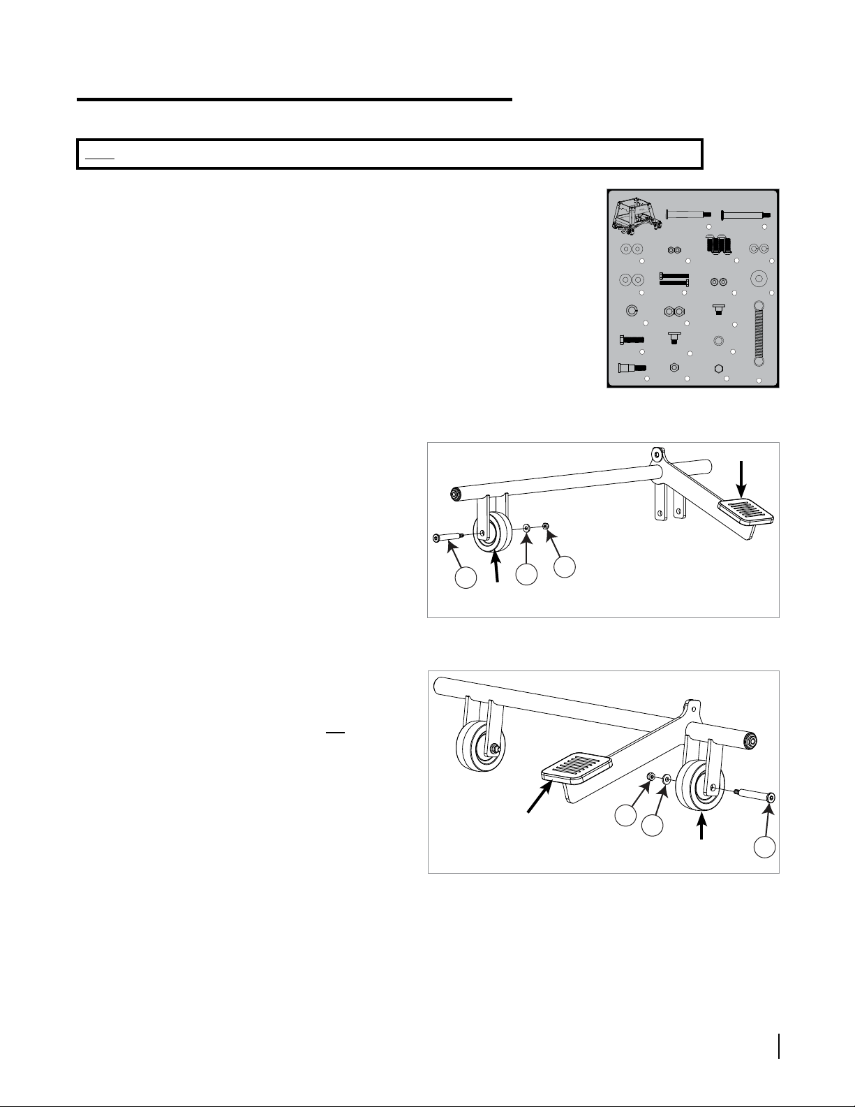
8. Mount the two casters to the outer corners of the
caster support by inserting the threaded shaft on
the casters through the corresponding holes in the
support and holding the casters in place with two
M10.5 x 25 washers, two M10.5 x 17 lock washers
and two caster nuts, as shown in Fig. 8. Fully
tighten the caster nuts with a 14 mm wrench.
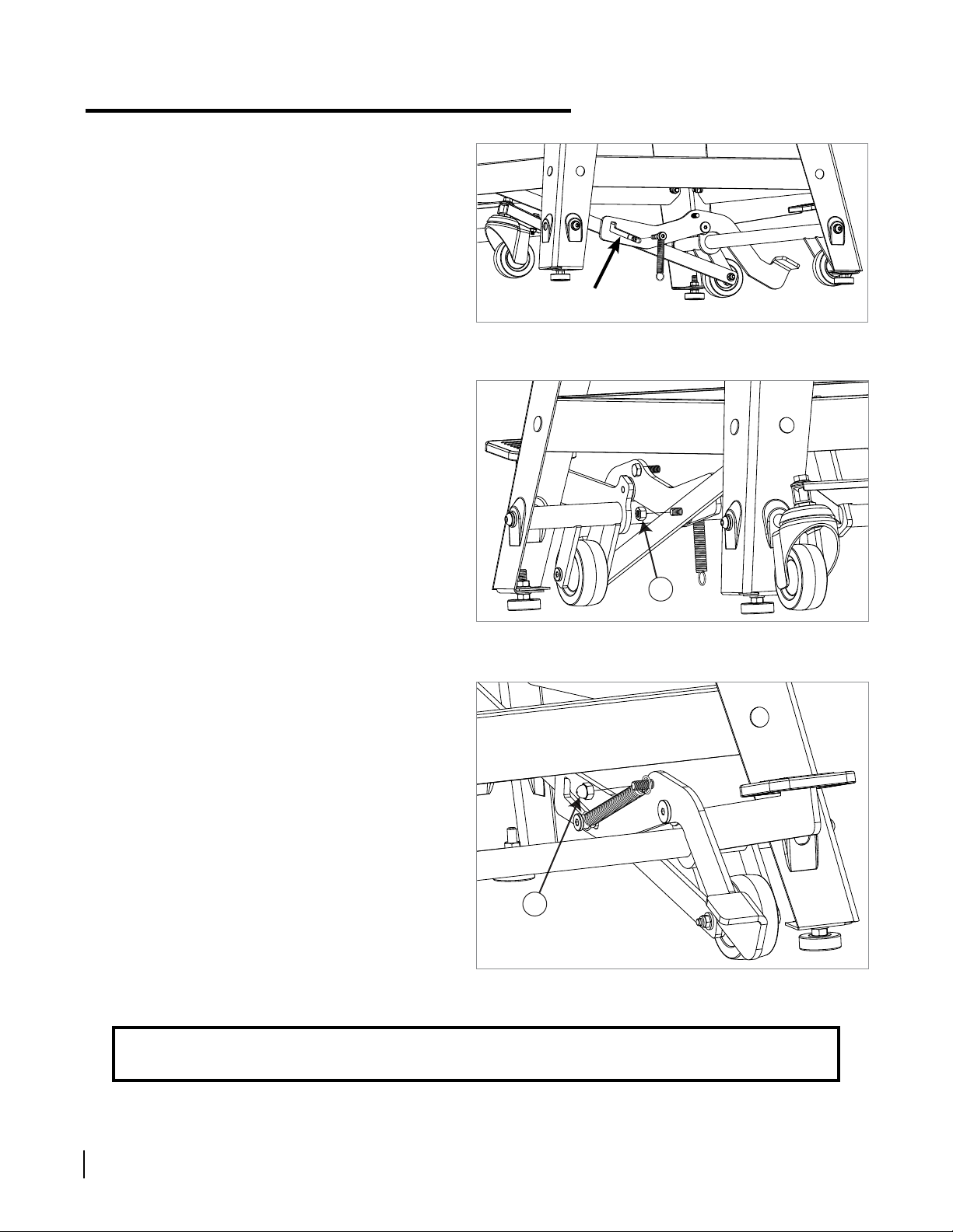
9. Next, install the linkage bar between the wheel
support and the caster support. To do this, remove
the M6 nylon hex nut and the M6 washer from the
axle for the wheel closest to the foot pad (this is
the nut that was not tightened in step 3), but do
not remove the axle or wheel. Locate the linkage
bar and note that it has a non-threaded hole at one
end and a plastic washer glued near the middle of
the linkage bar. Position the linkage bar so that the
plastic washer faces toward the inside of the stand,
and slide the non-threaded hole at the end of the
linkage bar over the exposed shoulder on the axle,
as shown in Fig. 9. Reinstall the M6 washer and
the M6 nylon hex nut on the axle and fully tighten
the nut with a 10 mm wrench and a 5 mm hex key.
10. Connect the other end of the linkage bar to the
connecting lever on the caster support by inserting
the M8 x 15.7 shoulder socket screw through the
hole in the connecting lever so that the hole ts
over the shoulder on the screw, and then threading
the screw into the threaded hole in the linkage bar,
as shown in Fig. 10. Fully tighten the shoulder
socket screw with a 5 mm hex key.
linkage
bar
linkage bar
connecting
lever
plastic washer
axle
non-threaded
hole
3 inch
caster

14
15 16
17
18
SawStop®Contractor Mobile Base 7
Installing Your Mobile Base
Fig. 11
Fig. 12
Fig. 13
11. Locate the release lever and the M8 x 30 hex
screw and fully thread the screw into the threaded
hole in the release lever (see Fig. 11).
release
lever
12. The release lever attaches to the foot pedal arm
of the wheel support. The release lever includes
a non-threaded hole, roughly in the middle of the
lever, that aligns with a threaded hole in the foot
pedal arm, as shown in Fig. 12. Place the M10.5
x 14.5 wave washer over the shoulder of the M8
x 17.7 shoulder socket screw. Then insert the
shoulder socket screw through the non-threaded
hole in the release lever so that the hole ts over
the screw’s shoulder, and then thread the screw
into the hole on the foot pedal arm. Fully tighten
the screw with a 5 mm hex key.
release
lever
foot pedal arm
13. Locate the extension spring and the release
lever locking screw. Note that the screw has two
shoulders, one with a larger diameter next to the
head, and one with a smaller diameter next to the
threads. Slide one end of the extension spring over
the larger shoulder (see Fig. 13).
larger shoulder
threaded hole
non-threaded
hole

19
20
SawStop®Contractor Mobile Base8
Installing Your Mobile Base
Fig. 16
Fig. 15
Fig. 14
Congratulations, your mobile base is now installed.
14. The end of the release lever opposite the foot pedal
includes a slot. Pivot the release lever until the slot
aligns with the plastic washer and threaded hole
in the middle of the linkage bar. Insert the release
lever locking screw through the slot in the release
lever and thread it into the hole in the linkage bar,
making sure to keep the extension spring on the
screw (see Fig. 14). Fully tighten the release lever
locking screw with a 5 mm hex key.
15. Locate the M8 nylon hex nut and thread it onto the
release lever locking screw to hold the screw in
place as shown in Fig. 15. Fully tighten the nut with
a 13 mm wrench.
16. Stretch the free end of the extension spring over
the end of the M8 x 30 hex screw that extends from
the release lever. Thread the M8 cap nut onto the
M8 x 30 hex screw to hold the extension spring in
place (see Fig. 16) , and fully tighten the cap nut
with two 13 mm wrenches.
release lever slot

SawStop®Contractor Mobile Base 9
Using Your Mobile Base
1. To move your saw with the mobile base, step down
on the foot pedal to raise the saw o the oor and
onto the wheels (see Fig. 17). Step on the foot
pedal until the release lever locking screw slides
into the locked position in the release lever. Make
sure that your foot does not come into contact with
the release lever while you are stepping on the
foot pedal to raise the saw, otherwise the mobile
base will not stay in the raised position.
2. Push the saw to its desired location. The mobile
base has two wheels on the left side and two
casters on the right side, and therefore it may be
easier to maneuver the saw by pushing from the
right side.
3. To unlock the release lever and lower the saw back
to the oor, step down on the foot pedal and the
release lever simultaneously (see Fig. 18). Slowly
lift your foot upwards to allow the saw to gently
lower to the oor. Do not step on the release lever
without having your foot on the foot pedal or your
saw will lower to the oor rapidly.
Fig. 17
Fig. 18
foot pedal -
step here
to raise
simultaneously
step on the foot pedal
and the release lever
to lower the saw
release lever
locking screw
locked position in
the release lever
release lever
Note: The SawStop Contractor Mobile Base
has been engineered to lift saws with or
without extension tables. You do not need an
additional arm extending out from the mobile
base to support your extension table.
However, if you have a SawStop 30” Out-Feed
Table attached you must remove it before
using the mobile base to move your saw.

1
1. Never place fingers, toes or other
body parts under the mobile base.
2. Always use the saw and the mobile
base on a level surface.
Never place fingers,
toes or other body parts
under the mobile base.
3. Lower the saw before use. Never use
the saw when it is raised off the floor.
4. Lower the saw slowly, do not let it
drop back to the floor.
!
WARNING
!
WARNING
Raise
Lower
2
3
3
3
3
4
4
5
56
6
7
7
8
8
9
9
11
10
12
13
14
15
17
18
19
20
21
22
23
24
25
26
26
27
27
28
29
29
30
31
32
33
34
10
11
12
16
SawStop®Contractor Mobile Base10
Contractor Mobile Base Exploded View

SawStop®Contractor Mobile Base 11
Contractor Mobile Base Parts List
No. Description Part No. Qty.
Complete Mobile Base Assembly MB-CNS-000 1
1Short Axle M6x67.6 MB-CNS-001 1
2Long Axle M6x73.8 MB-CNS-002 1
3M6x16x1.5 Washer MB-CNS-003 4
4M6 Nylon Hex Nut MB-CNS-004 2
5 M8x20 Button Head Socket Screw MB-CNS-005 4
6 M8x13.6 Lock Washer MB-CNS-006 4
7M8x18x1.5 Washer MB-CNS-007 4
8 M6x40 Hex Bolt MB-CNS-008 2
9 M6 Flange Lock Nut MB-CNS-009 2
10 M10.5x25 Washer MB-CNS-010 2
11 M10.5x17 Lock Washer MB-CNS-011 2
12 Caster Nut (3/8” thread) MB-CNS-012 2
13 M8x1.25x15.7 Shoulder Socket Screw MB-CNS-013 1
14 M8x30 Hex Screw MB-CNS-014 1
15 M8x1.25x17.7 Shoulder Socket Screw MB-CNS-015 1
16 M10.5x14.5 Wave Washer MB-CNS-016 1
17 Extension Spring MB-CNS-017 1
18 Release Lever Locking Screw MB-CNS-018 1
19 M8 Nylon Hex Nut MB-CNS-019 1
20 M8 Cap Nut MB-CNS-020 1
21 Wheel Support MB-CNS-021 1
22 Caster Support MB-CNS-022 1
23 Linkage Bar MB-CNS-023 1
24 Release Lever MB-CNS-024 1
25 Caster Support Plate MB-CNS-025 1
26 3” Wheel MB-CNS-026 2
27 3” Caster MB-CNS-027 2
28 Foot Pad MB-CNS-028 1
29 Plastic Spacer (Adhesive Backed) MB-CNS-029 2
30 SawStop Logo Label MB-CNS-030 1
31 Main Warning Label MB-CNS-031 1
32 Finger/Toe Warning Label MB-CNS-032 1
33 Raise Label MB-CNS-033 1
34 Lower Label MB-CNS-034 1
N/A Owner’s Manual MB-CNS-035 1
N/A Hardware Pack MB-CNS-036 1

October 2017
© SawStop, LLC
All Rights Reserved.
Updates of this manual may be available at www.sawstop.com.
SawStop, LLC
9564 S.W. Tualatin Road
Tualatin, Oregon 97062
www.sawstop.com
Main Phone - (503) 570-3200
Service - (503) 582-9934
Fax - (503) 570-3303
Email: [email protected]
Warranty
SawStop warrants to the original retail purchaser of the Contractor Saw Mobile Base accompanying
this manual that the mobile base will be free from defects in material and workmanship for ONE
YEAR from the date of purchase. This warranty does not apply to defects arising from misuse, abuse,
negligence, accidents, normal wear-and-tear, unauthorized repair or alteration, or lack of maintenance.
Please contact SawStop to take advantage of this warranty. If SawStop determines the mobile
base is defective in material or workmanship, and not due to misuse, abuse, negligence, accidents,
normal wear-and-tear, unauthorized repair or alteration, or lack of maintenance, then SawStop will,
upon proof of purchase and at its expense, send replacement parts to the original retail purchaser
necessary to cure the defect. Alternatively, SawStop will repair the mobile base, provided it is returned
to SawStop, shipping prepaid, within the warranty period.
SawStop disclaims any and all other express or implied warranties, including merchantability and
tness for a particular purpose. SawStop shall not be liable for death, injuries to persons or property,
or incidental, consequential, contingent or special damages arising from the use of the mobile base.
This warranty gives you specic legal rights. You may have other rights which, in the United
States, vary from state to state.
M CNS 19 0004 00
Other SawStop Saw manuals

SawStop
SawStop PCS175 User manual

SawStop
SawStop 10” User manual

SawStop
SawStop ICS31230 User manual

SawStop
SawStop RT-LFT User manual

SawStop
SawStop JSS User manual

SawStop
SawStop JOBSITE SAW PRO User manual

SawStop
SawStop CB31230 User manual

SawStop
SawStop CTS-120A60A User manual

SawStop
SawStop CTS-015 User manual

SawStop
SawStop CTS-120A60 User manual

SawStop
SawStop JSS-120A60 User manual

SawStop
SawStop PCS31230 User manual

SawStop
SawStop CNS175 User manual

SawStop
SawStop MC-CNS User manual

SawStop
SawStop T-Glide TGP2-FA Instruction Manual

SawStop
SawStop TGA-GA48 User manual

SawStop
SawStop JSS-MCA User manual

SawStop
SawStop JSS Manual

SawStop
SawStop JSS Manual

SawStop
SawStop ICS31240-50 User manual