Aeroqual AQM60 User manual
Aeroqual AQM60 User Guide

Page | 2
Aeroqual AQM60 User Guide
Contents
User Guide Revision History...........................................................................................................................5
1. Description ..............................................................................................................................................6
1.1. Control Module.................................................................................................................................. 7
1.2. Gas Treatment Module...................................................................................................................... 7
1.3. Gas Modules ..................................................................................................................................... 8
1.3.1. Gas Sensor Module Specifications............................................................................................. 9
1.4. TMS Module...................................................................................................................................... 9
1.5. Compressor..................................................................................................................................... 10
1.6. Power Module.................................................................................................................................. 10
1.7. Humidity and Temperature Sensor ................................................................................................. 10
1.8. Internal Air Duct............................................................................................................................... 11
1.9. Auxiliary Module (Optional) ............................................................................................................. 11
1.10. Particle Mass Pump Modules.......................................................................................................... 13
1.10.1. Profiler Pump Module ............................................................................................................... 13
1.10.2. Nephelometer Particle Monitor ................................................................................................. 13
1.11. Electrical Connections..................................................................................................................... 14
1.12. Pneumatic Connections .................................................................................................................. 15
2. Installation and Commissioning .........................................................................................................16
2.1. Unpacking........................................................................................................................................ 16
2.2. Assembly......................................................................................................................................... 16
2.2.1. Connect Mains Power............................................................................................................... 16
2.2.2. Connect Inlet Sub Assembly..................................................................................................... 17
2.2.3. Assembly of heated inlet for PM/Profiler (Optional).................................................................. 18
2.2.4. Connect third party sensors (Optional)..................................................................................... 19
2.3. Initial Commissioning ...................................................................................................................... 19
2.3.1. Set Up....................................................................................................................................... 19
2.3.2. System Checks......................................................................................................................... 20
2.3.3. System Values.......................................................................................................................... 21
2.3.4. Zero and Span Checks for Gas Modules.................................................................................. 21
3. AQM60 Software Description ..............................................................................................................22
3.1. Computer Requirements ................................................................................................................. 22
3.2. Summary......................................................................................................................................... 22
3.2.1. File ............................................................................................................................................ 22
3.2.2. Setup......................................................................................................................................... 23
3.2.3. Data........................................................................................................................................... 23
3.2.4. Tools ......................................................................................................................................... 24
3.2.5. Calibration................................................................................................................................. 24
3.2.6. Diagnostics ............................................................................................................................... 25
3.2.7. Additional Buttons..................................................................................................................... 25
3.3. IP Modem configuration (Optional).................................................................................................. 26
3.3.1. TCP/IP connection.................................................................................................................... 26
3.3.2. IP address solutions using GPRS Systems.............................................................................. 27
3.4. Other Communication Options........................................................................................................ 28
3.4.1. RF Modem ................................................................................................................................ 28
3.4.2. GSM Modem............................................................................................................................. 28
4. Calibration .............................................................................................................................................30
4.1. Calibration Frequency..................................................................................................................... 30
4.2. AQM Calibration Basics .................................................................................................................. 31
4.2.1 Nafion Humidifier (AQM R21) ...................................................................................................... 31
4.3. Zero Calibration and Check............................................................................................................. 32
4.3.1. Automatic Zero............................................................................................................................. 32
4.3.2. Manual Zero................................................................................................................................. 32
4.4. Span Calibration and Check............................................................................................................ 33
4.4.1. Multi-Gas Calibration Standard and Gas Phase Titration......................................................... 34

Page | 3
Aeroqual AQM60 User Guide
4.4.2. Span Calibration Procedure...................................................................................................... 34
4.5. AirCal 8000 (Optional)..................................................................................................................... 35
4.5.1. Overview................................................................................................................................... 35
4.5.2. Pneumatics............................................................................................................................... 36
4.5.3. Gas cylinder Housing................................................................................................................ 36
4.5.4. Configuring the AirCal 8000 scheduler..................................................................................... 37
4.5.5. The Calibration Record............................................................................................................. 38
4.5.6. Performing a Manual Calibration .............................................................................................. 39
4.5.7. Data Displayed.......................................................................................................................... 39
5. Third Party Sensors..............................................................................................................................41
5.1. Particle Monitor................................................................................................................................ 41
5.1.1. Nephelometer ........................................................................................................................... 41
5.1.2. Inlet heater................................................................................................................................ 41
5.1.3. Inbuilt filters............................................................................................................................... 41
5.2. Profiler............................................................................................................................................. 41
5.2.1. Optical Particle Counter............................................................................................................ 41
5.2.2. Connections.............................................................................................................................. 42
5.2.3. Data Outputs............................................................................................................................. 42
5.3. Vaisala Weather Transmitter WXT520............................................................................................ 43
5.4. Sensirion T/RH Sensor SHT75 ....................................................................................................... 43
5.5. Gill WindSonic................................................................................................................................. 44
5.6. Noise Meter and Calibrator ............................................................................................................. 44
6. Field Installation....................................................................................................................................45
6.1. Site Selection................................................................................................................................... 45
6.2. Mounting.......................................................................................................................................... 45
7. Maintenance ..........................................................................................................................................47
7.1. Safety Requirements....................................................................................................................... 47
7.2. Maintenance Schedule.................................................................................................................... 47
7.2.1. Standard AQM .......................................................................................................................... 47
7.2.2. Particle Monitor......................................................................................................................... 48
7.2.3. Profiler....................................................................................................................................... 48
7.3. AQM Maintenance Procedures....................................................................................................... 48
7.3.1. Replacing the Inlet Filter........................................................................................................... 48
7.3.2. Measuring Sample Inlet Flow Rate........................................................................................... 49
7.3.3. Gas Sensor Module Flow Rate................................................................................................. 49
7.3.4. Replacing Gas Treatment Media.............................................................................................. 51
7.3.5. Leak Check Gas Sensor Plumbing........................................................................................... 52
7.3.6. Removing and Replacing AQM Modules.................................................................................. 52
7.4. Particle Monitor................................................................................................................................ 53
7.4.1. Sample Flow Check.................................................................................................................. 53
7.4.2. Purge Flow Check..................................................................................................................... 54
7.4.3. Sheath Flow Check................................................................................................................... 54
7.4.4. Leak Check............................................................................................................................... 54
7.4.5. Manual Zero Air Check............................................................................................................. 55
7.4.6. Fibre Span Check ..................................................................................................................... 55
7.4.7. Laser Current Check................................................................................................................. 56
7.4.8. Filter Changes........................................................................................................................... 56
7.4.9. Cyclone and Inlet Cleaning....................................................................................................... 56
7.4.10. Pump Module Removal............................................................................................................. 57
7.5. Profiler............................................................................................................................................. 57
7.5.1. Sample Flow Check and Adjustment ....................................................................................... 57
7.5.2. Sheath Flow Check................................................................................................................... 58
7.5.3. Leak Check............................................................................................................................... 58
7.5.4. Filter Changes........................................................................................................................... 59
7.5.5. Inlet Cleaning............................................................................................................................ 60
7.5.6. Pump Module Removal............................................................................................................. 60

Page | 4
Aeroqual AQM60 User Guide
8. Troubleshooting....................................................................................................................................61
8.1. AQM60 Basics................................................................................................................................. 61
8.2. Particle Monitor/Profiler................................................................................................................... 62
8.3. Diagnostics...................................................................................................................................... 63
9. Orbit Data...............................................................................................................................................65
9.1. Specifications .................................................................................................................................. 65
9.2. Configuring the Orbit Modem.......................................................................................................... 65
9.3. Using the Orbitdata Website ........................................................................................................... 66
9.3.1. Using the Graphs...................................................................................................................... 67
9.3.2. Setting Alarms........................................................................................................................... 68
9.3.3. Downloading Data..................................................................................................................... 68
10. Appendix 1.............................................................................................................................................69
10.1. Sensor list........................................................................................................................................ 69
10.1. Auxiliary Module Wiring................................................................................................................... 70
10.1.1. Wind Sonic................................................................................................................................ 70
10.1.2. Vaisala ...................................................................................................................................... 70
10.2. RS232 Protocol ............................................................................................................................... 71
11. Appendix 2.............................................................................................................................................82
11.1. Guidelines........................................................................................................................................ 82
11.2. Technical support............................................................................................................................ 82
11.3. Copyright......................................................................................................................................... 82
11.4. Compliance...................................................................................................................................... 83

Page | 5
Aeroqual AQM60 User Guide
User Guide Revision History
Current version: 7.3
Description: User guide for AQM60
This user guide is a newly created document for the use of the AQM60.
Date
Revision number
Description of change
Affected pages
10/02/2014
7.1
Orbit data information
added
Section 9
30/05/2014
7.2
New Aux module
information added
Section 1.8
30/05/2014
7.2
Connection of inlet sub
assembly
Section 2.2.2
07/07/2014
7.3
Internal Fan Duct
Information
Added additional photo to
inlet sub assembly
Added note about
increasing logging period
above 2 minutes in
calibration section.
Section 1.8
Section 2.2.2
Section 4.5.4
Page | 6
Aeroqual AQM60 User Guide
1. Description
The Aeroqual AQM60 Environmental Station is a custom-built ambient air quality instrument. It’s platform is
configurable to measure common air pollutants including ozone (O3), nitrogen dioxide (NO2), carbon
monoxide (CO) and sulphur dioxide (SO2) as well as particulate matter (PM10, PM2.5) and meteorological
parameters such as temperature, humidity, wind speed and direction.
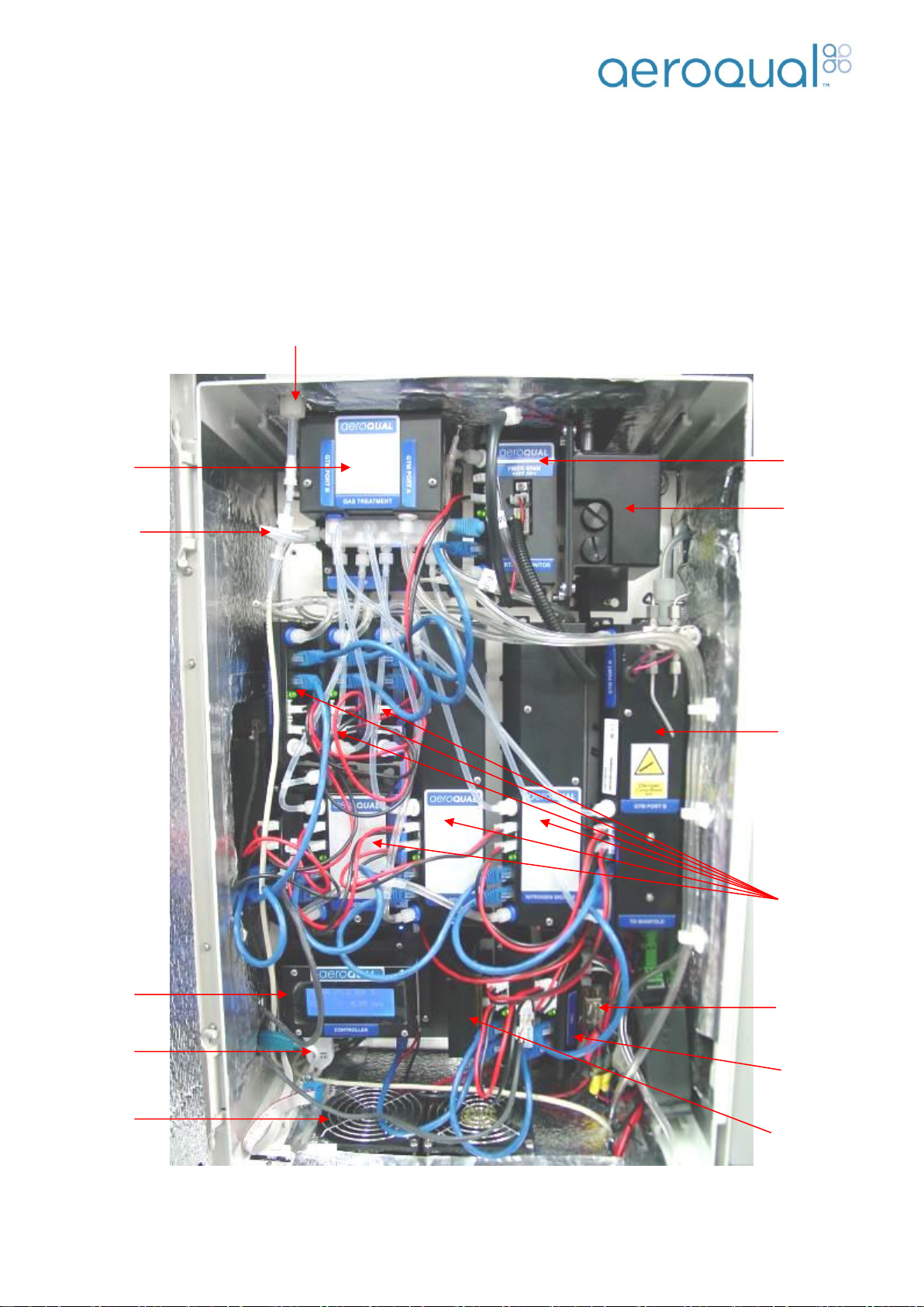
The AQM consists of an enclosure typically containing a control module, power module, thermal
management system, gas treatment module, a number of gas sensor modules, a RH/T sensor and
associated cabling and plumbing.
Note 1: The placement of individual modules will vary depending on the user configuration
Note 2: AQM60 units dispatched from July 2014 will also include an internal air duct (Refer to Section 1.8)
Heater
Inlet Filter
Pump module
PM or Profiler
engine
Aircal 8000
(Optional)
Gas Modules
(User
Configurable)
Cooling
Fans
RS232 to
USB Adapter
Control
Module
Inlet
Gas Treatment
Module
Mains Power
12V connector
terminal
Thermal
Management
System (TMS)
Page | 7
Aeroqual AQM60 User Guide
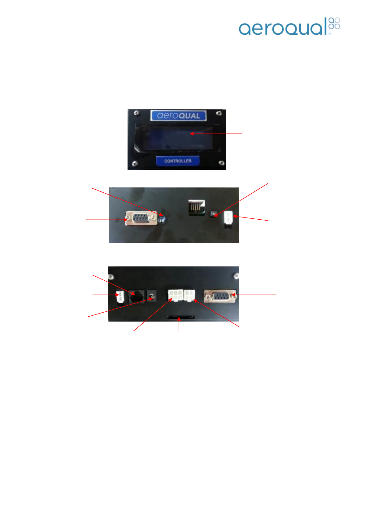
1.1. Control Module
The control module is the interface between the RS485 sensor bus and data communication links. It contains
a display, a SD data card which logs data, a RS232 serial connector for external communication, a bus
connector for internal communication with the sensor modules and a cable connector for the Sensirion
Humidity and Temperature sensor (if fitted).
The AQM60 is supplied with a RS232 to USB adapter fitted between the Control Module and an external
USB socket fitted at the side of the enclosure. This enables the user to perform a wide range of functions
over the USB connection, without needing to open the enclosure door, such as data logging and various
system checks using the supplied Aeroqual AQM60 PC software
Note: The driver for the RS232 to USB adapter is in the software CD which comes with the
instrument.
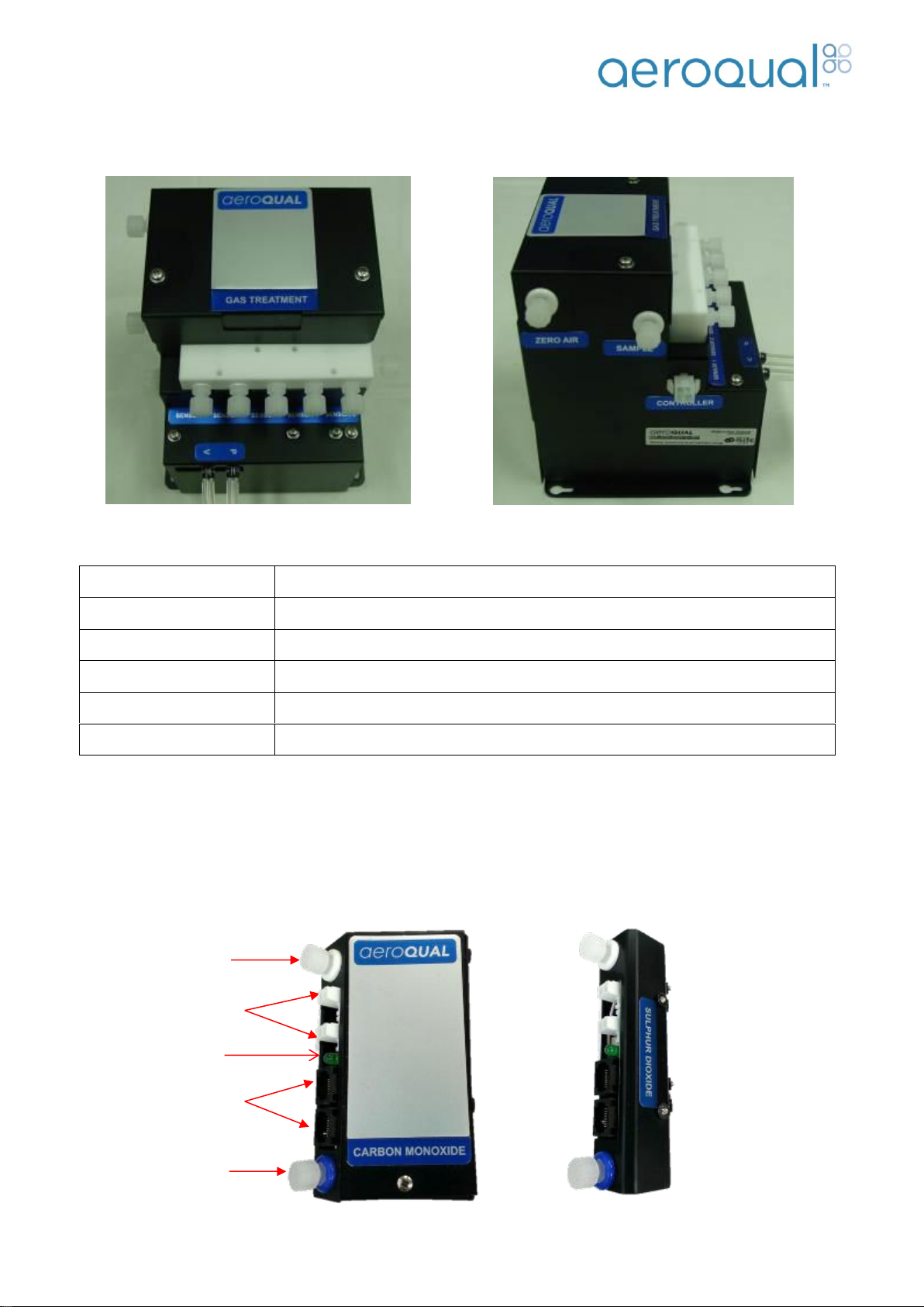
1.2. Gas Treatment Module
The Gas Treatment Module controls the gas sampling. Inlet air is filtered through a 5 μm membrane filter and
enters the Gas Treatment Module via either the sample or zero air ports. The air is then distributed via a
PTFE manifold to the gas modules. A solenoid controls the air path which can be switched from the directly
sampled ambient air to air which has passed through internal scrubbers (zero air) in order to check the
baseline readings of the gas sensors.
Removable Display module
Front
Top
Off/On switch with LED
Controller 12VDC power input
Programming Port
RS232
Firmware (V6.2+)
Programming Dip
Switch
Firmware (V6.2+)
Base
6 way Gas Treatment
SD Card Slot
DB9 RS232
4 way T/RH
2 way Bus relay
activation
RJ45 RS485
Bus
2.1mm 12VDC relay
switched Power output
Page | 8
Aeroqual AQM60 User Guide
The Gas Treatment Module also contains a diaphragm pump which draws air through the gas modules. The
sample flow rate is controlled by a bypass screw fitted between the vacuum and pressure sides of the pump.
Note: If the AQM60 has an AirCal 8000 installed the zero air scrubbing material is located in the
AirCal module not the GTM.
1.3. Gas Modules
An example of a gas module is shown below. All modules are mounted onto the base plate using 4 or 2
bolts. They can be either full size or half size modules depending on the gas. Inlet and outlet tubes are
connected to the gas distribution manifold and exhaust respectively.
Solenoid
12VDC, 3-way, Teflon
Pump
BLDC diaphragm pump
Scrubber media
1 x activated carbon + 1 x Hopcalite + 1 x Purafil Chemisorbent
Manifold
PTFE
Fittings
Luer
Flow rate
0.2 to 1.5 LPM depending on gas modules fitted. Set by bypass screw
Sample Exhaust
RJ45 Connectors
for RS485 bus
12VDC Power
Connectors
Sample inlet
Status LED
Page | 9
Aeroqual AQM60 User Guide
1.3.1. Gas Sensor Module Specifications
(Note: these are subject to change; please contact Aeroqual for latest performance data)
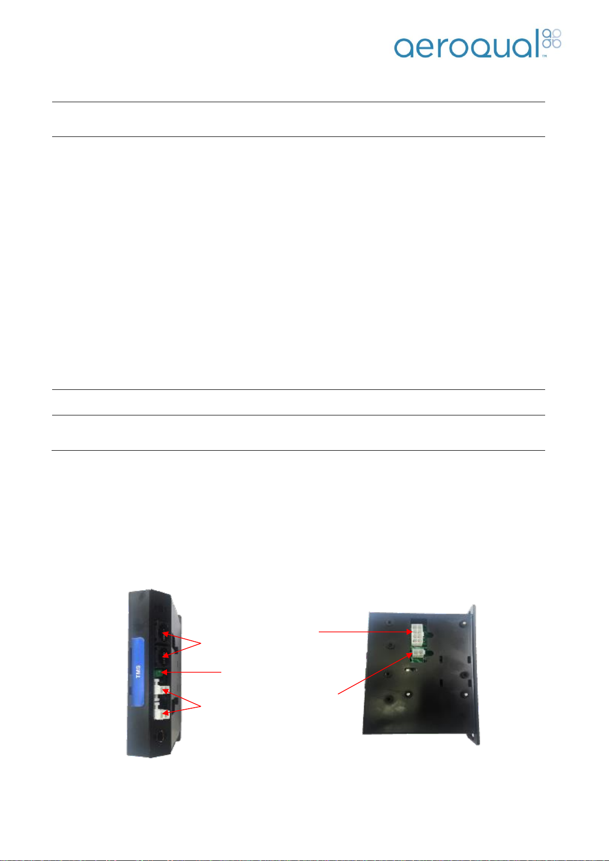
1.4. TMS Module
The AQM has a thermal management control system to maintain a stable internal temperature irrespective of
ambient temperature changes. The TMS module controls the thermal management system to ensure the
internal temperature is maintained. It initiates the fans and heater when necessary to maintain the internal
temperature set.
Gas Modules
Range
Minimum
Detection
Limit
Accuracy of
Factory Calibration
Precision
Resolution
Ozone O3(GSS)
0-0.15 ppm
0.001 ppm
<±0.005 ppm
0.002 ppm
0.001 ppm
Ozone O3(GSS)
0-0.5 ppm
0.001 ppm
<±0.008ppm 0to0.1ppm;
<±10% of reading above 0.1 ppm
0.005 ppm
0.001 ppm
Nitrogen Dioxide NO2(GSS)
0-0.2 ppm
0.001 ppm
<±0.01 ppm 0to 0.1 ppm;
<±10%of readingabove 0.1ppm
0.005 ppm
0.001 ppm
Nitrogen Oxides NOx(GSS)
0-0.5 ppm
0.001 ppm
<±0.01 ppm 0to 0.1 ppm;
<±10%of readingabove 0.1 ppm
0.005 ppm
0.001 ppm
Carbon Monoxide CO (GSE)
0-25 ppm
<0.04 ppm
<±0.1ppm, 0 to 1 ppm
<±10% of reading above 1 ppm
0.1 ppm
0.01 ppm
Carbon Dioxide CO2(NDIR)
0-2000 ppm
<10 ppm
<±(10 ppm + 5% of reading)
10 ppm
1 ppm
Hydrogen Sulphide H2S(GSE)
0-10 ppm
<0.03 ppm
<±0.05ppm 0 to 0.5 ppm
<±10% of reading above 0.5ppm
0.03 ppm
0.01 ppm
Sulphur Dioxide SO2(GSE)
0-10 ppm
<0.03 ppm
<±0.05ppm 0 to 0.5 ppm
<±10% of reading above 0.5 ppm
0.05 ppm
0.01 ppm
Volatile Organic Compounds
(PID)
0-20 ppm
0.01 ppm
<±0.02ppm 0 to 0.2 ppm
<±10% of reading above 0.2 ppm
0.03 ppm
0.01 ppm
Non-methane Hydrocarbon (GSS)
0-25 ppm
<0.1 ppm
<±0.1ppm, 0 to 1 ppm
<±10% of reading above 1 ppm
0.1 ppm
0.01 ppm
Volatile OrganicCompounds
(GSS)
0-25 ppm
<0.1 ppm
<±0.1ppm, 0 to 1 ppm
<±10% of reading above 1 ppm
0.1 ppm
0.01 ppm
Particle Monitor (nephelometer)
Sizes
PM1PM2.5 or PM10
Range
0-2000 µg/m3
Accuracy
<±(2 µg/m3 + 5% of reading)
Flow rate
2.0 LPM
Resolution
0.01 µg/m3
Particle Profiler (OPC)
Sizes
PM1PM2.5 and
PM10
Range
0-500 µg/m3
Accuracy
<±(5 µg/m3 +15% of reading)
Flow rate
1.0 LPM
Resolution
0.01 µg/m3
Status
LED
12VDC
Power
Connectors
RJ45 Connectors
for RS485 bus
TMS
communication
connector
ITemp
Sensor
Connector
Page | 10
Aeroqual AQM60 User Guide
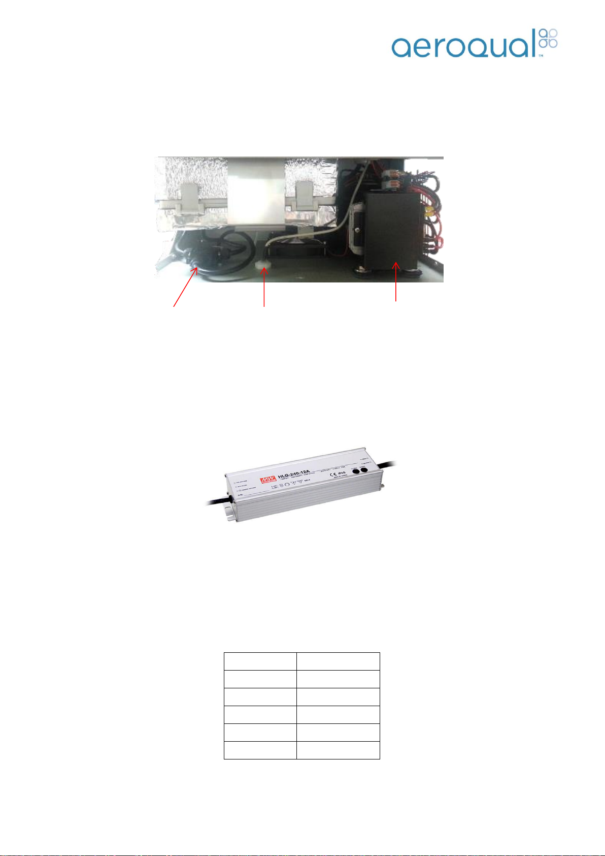
1.5. Compressor
The cooling system is a compressor refrigeration unit which is mounted at the base of the AQM60. It is a
self-contained system that provides cooling via the base on the AQM. The compressor system and inlet can
be accessed by releasing the two clips on the side of the AQM and rotating the housing upwards.
1.6. Power Module
Two Meanwell HLG240-12A 192W 12V Single Output Class 2 with PFC Power Units are mounted on the
outside of the enclosure. One powers the compressor and the second powers the modules. It has features
including universal AC input (90-280VAC) and IP65 rating.
1.7. Humidity and Temperature Sensor
The Humidity and Temperature Sensor is a Sensirion single chip device which contains a capacitive polymer
sensing element for relative humidity and a band-gap temperature sensor. More detailed specifications are in
the table below. The temperature and humidity sensor is housed in a connector located on the bottom of the
enclosure. It is connected directly to the Control Module.
Humidity
Resolution
0.1 %RH
Range
0 to 100 %RH
Temperature
Resolution
0.1 °C
Range
-40 to 120 °C
Temperature &
Relative Humidity
Sensor
Compressor
Junction box for
mains connection
Page | 11
Aeroqual AQM60 User Guide
Programming Dip
Switch
Programming
Port
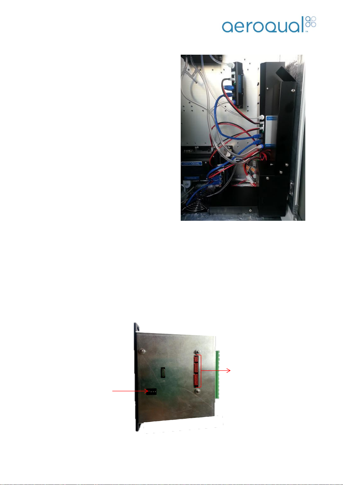
1.8. Internal Air Duct
AQM60 units dispatched after July 2013 will include an
internal air duct (chimney). The chimney is a new
feature to improve thermal stability inside the AQM60
base system. Changes to both the heating and cooling
sub-systems ensure optimum airflow around the
enclosure, minimising thermal gradients thus
temperature effects on the sensors. This optimised
airflow has been coupled with enhancements to the
thermal measurement and control sub-system allowing
an even tighter temperature control ban.
The chimney will come pre-installed. However, there will
be times when the chimney may need to be removed
for servicing.
To remove the chimney the two screws, that connect
the chimney to the fan grill on the base of the
enclosure, need to be removed. The chimney should
then slide out and the two connectors behind can be
easily disconnected.
Note 1: The chimney is stuck to the side of the enclosure with double sided tape which may need to
be replaced when removing/replacing the chimney.
Note 2: The NOx/NO2 module can be removed without taking out the chimney by undoing the
mounting plate screws completely and sliding the module out.
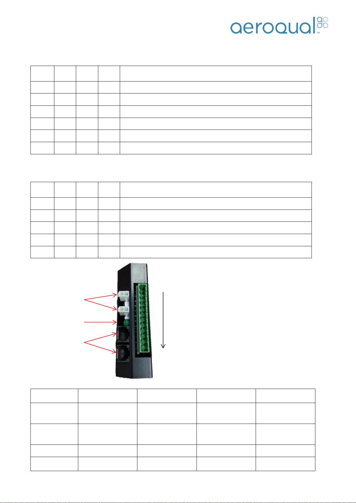
1.9. Auxiliary Module (Optional)
The auxiliary module acts as an interface between third party sensors and the AQM60 communication bus.
It is configured with different operating modes which can be selected by using the dipswitches located on the
side of the module. Aeroqual has integrated a number of third party sensors and is able to supply the
auxiliary module preconfigured for your sensors.
Page | 12
Aeroqual AQM60 User Guide
Firmware: AUX_MODULE_01.
Use for: Analogue inputs, Vaisala WXT520 weather, Gill Windsonic wind, Cirrus MK:427 noise.
1
2
3
4
Function
OFF
OFF
OFF
OFF
Default - standard Auxiliary module with AN1, AN2, Freq
ON
OFF
OFF
OFF
Vaisala WXT520 with RS232 communication + AN1, AN2, Freq
OFF
ON
OFF
OFF
Vaisala WXT520 with RS232 communication + Cirrus MK427 Noise
ON
ON
OFF
OFF
Wind Sonic with RS232 communication + AN1, AN2, Freq
OFF
OFF
ON
OFF
Wind Sonic with RS232 communication + Cirrus MK427 Noise
ON
OFF
ON
OFF
Cirrus MK427 Noise module only
Firmware: AUX_MODULE_02.
Use for: Analogue inputs, Met One MSO weather, Met One 034b wind, Cirrus MK:427 noise.
1
2
3
4
Function
OFF
OFF
OFF
OFF
Default - standard Auxiliary module with AN1, AN2, Freq
ON
OFF
ON
OFF
Cirrus MK427 Noise module only
OFF
ON
ON
OFF
Met One MSO with RS232 communication + Cirrus MK427 Noise
ON
ON
ON
OFF
Met One MSO with RS232 communication + AN1, AN2, Freq
OFF
OFF
OFF
ON
Met One 034B analogue module + Cirrus MK427 Noise
Example of wiring:
Wind Sonic
(Pin 1) GND,
SIGNAL GND
(Pin 2) 12V
(Pin 5) RX
(Pin 6) TX
Vaisala
(Pin 1) GND for
operating, data &
heating
(Pin 2) 12V for
operating & heating
(Pin 5) RX
(Pin 6) TX
Met One MSO
(Pin 1) GND,
SIGNAL,
COMMON, SHIELD
(Pin 2) 12V
(Pin 5) RX
(Pin 6) TX
Met One 034B
(Pin 1) GND
(Pin 12) VCC
(Pin7) WD
(Pin 9) WS
Cirrus MK:427
(Pin 1) GND,
ACTUATOR GND
(Pin 2) 12V, LOOP
IN
(Pin 8) LOOP OUT
(Pin 12)
ACTUATOR IN
Pin 12
Pin 1
Status LED
12VDC Power
Connectors
RJ45 Connectors
for RS485 bus
Wiring of Aux Module:
PIN 1: GND
PIN 2: 12V FUSED
PIN 3: RESERVED
PIN 4: RESERVED
PIN 5: RX
PIN 6: TX
PIN 7: 0-5V IN
PIN 8: 4-20mA IN
PIN 9: FREQ IN
PIN 10: AGND
PIN 11: METONE 034B PWR
PIN 12: TIMED RELAY
Page | 13
Aeroqual AQM60 User Guide
A programming port is also exposed through the side of the module to allow custom programs to be loaded
into the module.
Note 1: Aeroqual can supply a standard programming tool for distributors to reprogram the auxiliary
module to the specified requirements.
Note 2: Please refer to third party sensor manuals for instructions on wire outputs. The Wind Sonic
comes with an Aeroqual supplied cable and therefore wire outputs will be sent with the cable.
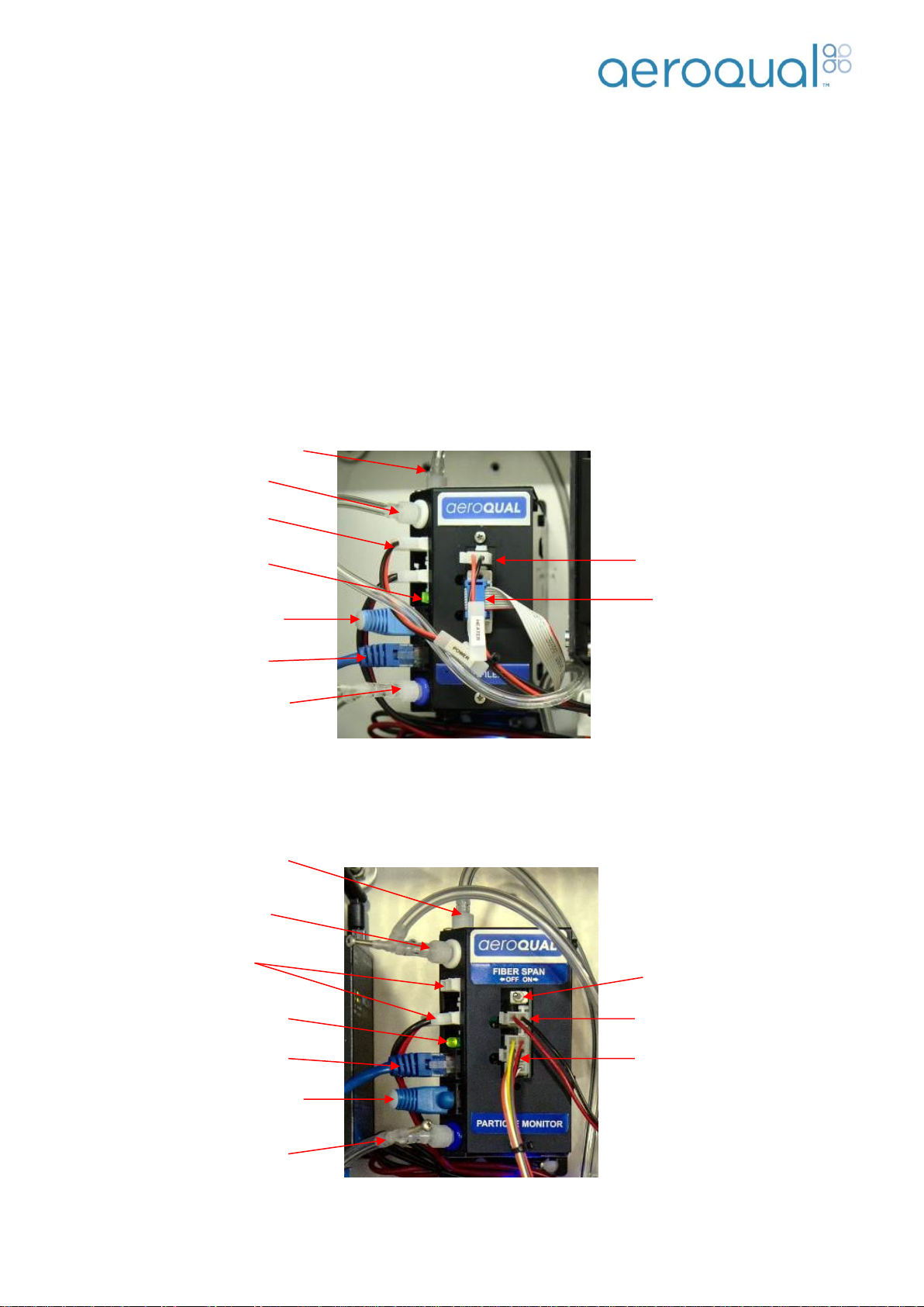
1.10. Particle Mass Pump Modules
The Pump Modules for the optical mass sensors contain a microprocessor for mass calculation and a pump
for sampling. There is a different pump module for the Nephelometer and optical particle counter (Profiler)
sensor modules
1.10.1. Profiler Pump Module
1.10.2. Nephelometer Particle Monitor
Purge line
Exhaust line with
flow adjuster
Inlet heater connector
RS232 connector from
optical engine.
12VDC power
connection
RS485 termination
dongle
RS485 bus cable
Sample line
Power on LED
Inlet heater connector
Cable from optical engine
12VDC power
connection
RS485 termination dongle
RS485 cable
Exhaust line with flow
adjuster
Power on LED
Sample in
Sheath air out with
flow adjuster
Fibre span switch
Page | 14
Aeroqual AQM60 User Guide
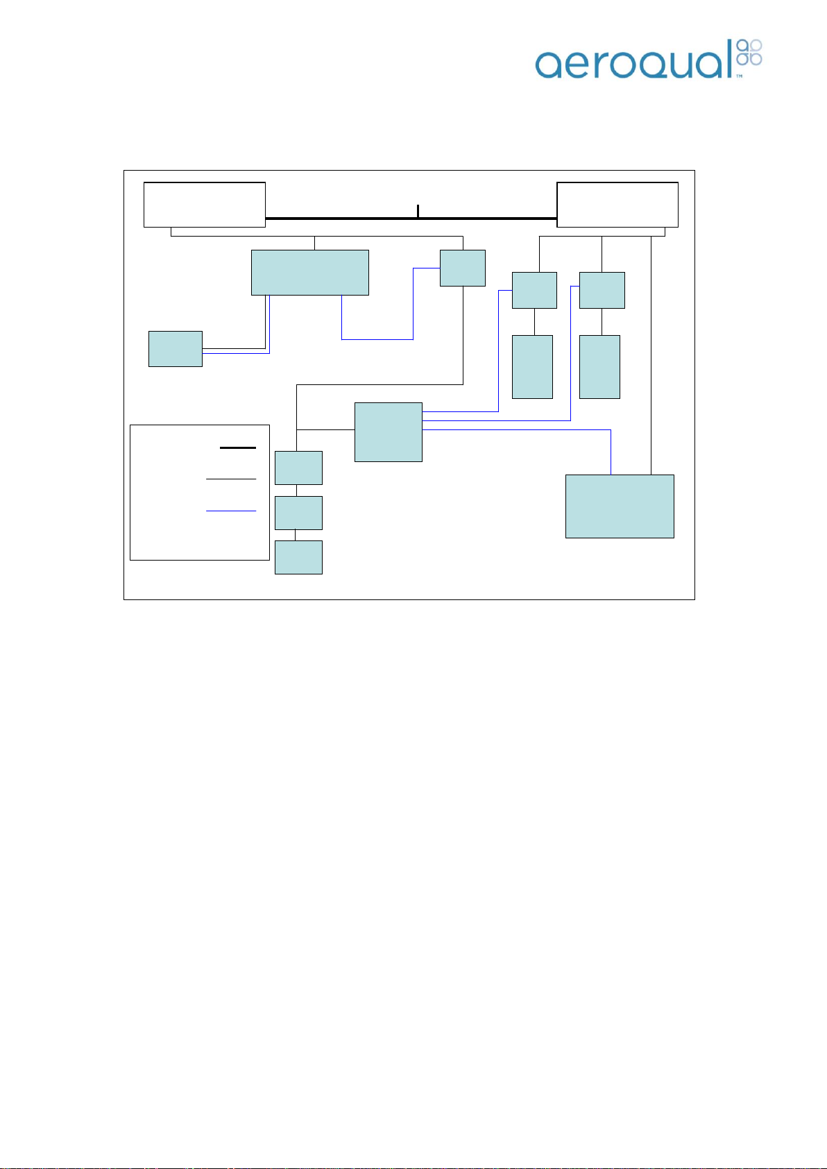
1.11. Electrical Connections
RS485 Bus
The two wire RS485 bus connections are made using 20 cm CAT5 cables between the sensor modules. The
last module on the bus also has a blue termination dongle fitted. The termination dongle should not be
removed.
12 VDC Power Bus
All modules inside the AQM60 operate from the 12VDC power. The power is supplied by a daisy chain of
black and red cables. A relay is activated by the Control Module on/off button to allow the sensor bus to be
powered.
Status LED
Each module includes a status LED which indicates that the electrical status of the module is functioning
correctly. It does not relate the calibration status of the module.
a) Continuous on indicates correct electrical functionality
b) Slow flash (1 second) indicates warm up period
c) Fast flash (0.2 seconds) sensor failure
d) LED not on indicates no power to module.
Controller
GTM
Power supply one
12V
Compressor
Module
power
relay
TMS
module
gas
module
gas
module
Heater
power
relay
TMS heater
12 V Power
Signal
Power supply two
12V
Mains Power
Mains power in
Fan
relay
TMS fans
TMS = thermal
management system
Controller
GTM
Power supply one
12V
Compressor
Module
power
relay
TMS
module
gas
module
gas
module
Heater
power
relay
TMS heater
12 V Power
Signal
Power supply two
12V
Mains Power
Mains power in
Fan
relay
TMS fans
TMS = thermal
management system
Controller
GTM
Power supply one
12V
Compressor
Module
power
relay
TMS
module
gas
module
gas
module
Heater
power
relay
TMS heater
12 V Power
Signal
Power supply two
12V
Mains Power
Mains power in
Fan
relay
TMS fans
TMS = thermal
management system
Controller
GTM
Power supply one
12V
Compressor
Module
power
relay
TMS
module
gas
module
gas
module
Heater
power
relay
TMS heater
12 V Power
Signal
Power supply two
12V
Mains Power
Mains power in
Fan
relay
TMS fans
TMS = thermal
management system
Controller
GTM
Power supply one
12V
Compressor
Module
power
relay
TMS
module
gas
module
gas
module
Heater
power
relay
TMS heater
12 V Power
Signal
Power supply two
12V
Mains Power
Mains power in
Fan
relay
TMS fans
TMS = thermal
management system
Page | 15
Aeroqual AQM60 User Guide
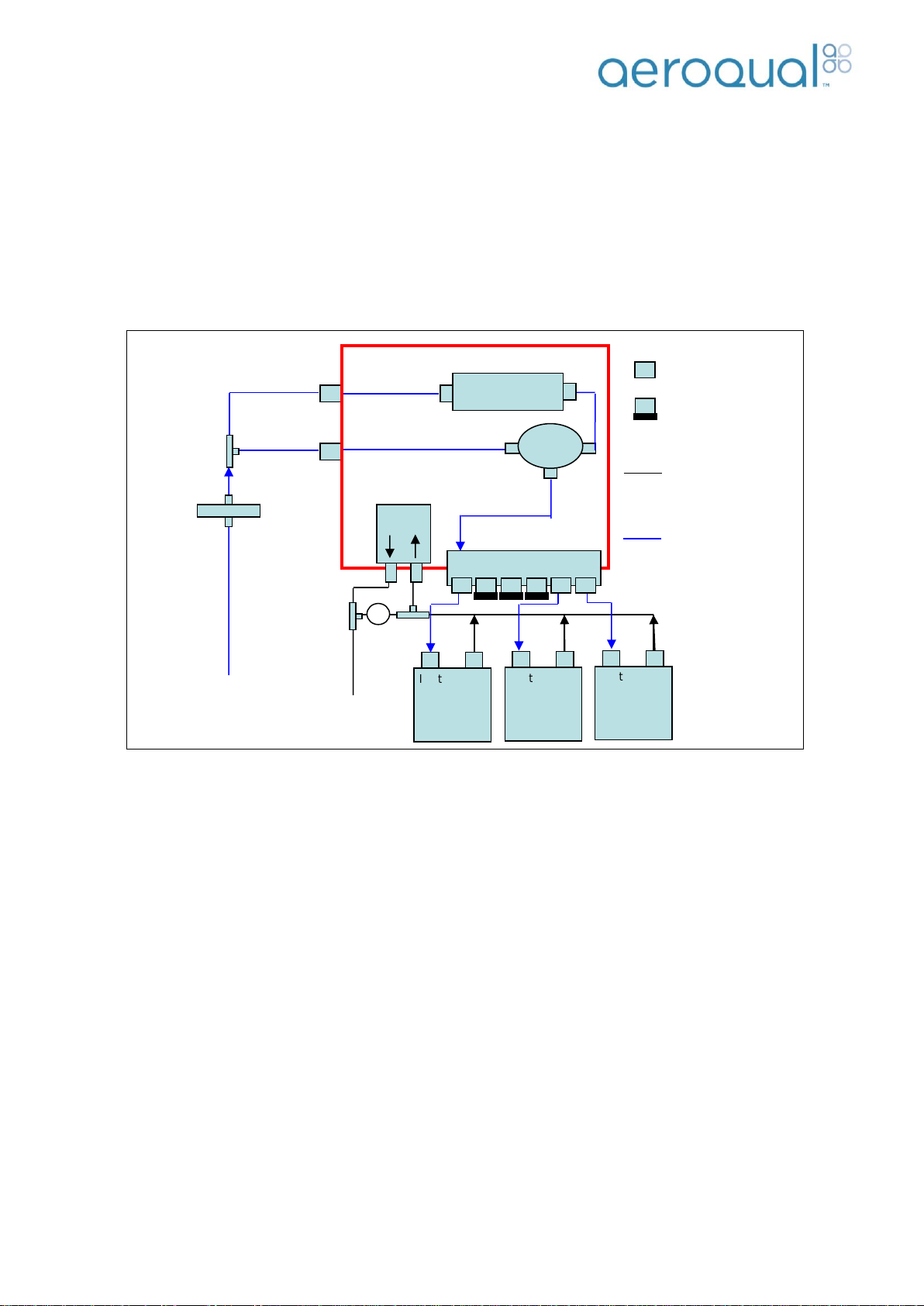
1.12. Pneumatic Connections
The airlines and connections are shown in the figure below for a three gas AQM. The sample gas passes
into the Gas Treatment Module (GTM) and is distributed to the sensors via a PTFE manifold. The gas
modules sample from the PTFE manifold via a central pump located in the gas treatment module. The
solenoid can switch between the ambient air sample and air which has passed through an absorbent
scrubber for baseline measurements. The sample inlet tubing is PTFE tubing which is inert and smooth
walled. The module exhaust tubing is Tygon 3603 PVC tubing.
Note: The ports on the manifold which are not used must be capped off to prevent leaks.
An adjustable bypass valve is included between the vacuum and pressure side of the pump. This is to allow
an adjustment to be made to the module flow rates and to relieve the excess pressure placed on the pump
when only one or two modules are installed.
The total sample flow rate will be dependent on the number of gas sensor modules in the AQM. All module
flows are controlled by critical orifices located within the sensor modules. See Section 7.3.3.for expected flow
rates.
AQM inlet
¼’ Swagelok
compression fitting
Solenoid
Pump
Zero
Scrubber
Inlet
Exhaust
Gas
Module
Inlet
Exhaust
Gas
Module
Inlet
Exhaust
Gas
Module
AQM exhaust
= Luer fitting
= Capped luer
fitting
= Tygon tubing
= PTFE tubing
Filter 5 µm
PTFE
Flow
Bypass
Valve
Gas treatment module (GTM)

Page | 16
Aeroqual AQM60 User Guide
2. Installation and Commissioning
The purpose of this section is to enable the user to correctly assemble, commission, and install their AQM.
Undertaking the commissioning procedure correctly is an important part of the product
transfer process and customer acceptance. It confirms that you have received the product in
good working order and it has been shipped to you without damage.
The full commissioning process will require gas calibration and flow equipment (not supplied with the AQM).
In the absence of gas calibration and flow measurement capabilities, measurement of outside air over a 24
hour period and comparison of this data with measurements from a local “reference” air monitoring station
will provide evidence of correct span operation.
2.1. Unpacking
a) Examine the Shockwatch label on the side of the shipping box. If the indicator is red do not refuse
shipment. Make a notification on delivery receipt and inspect for damage. If damage is discovered,
leave item in original packaging and request immediate inspection from carrier within 15 days of
delivery date (3 days international).
b) Verify the serial number label on the documentation matches the serial label on the AQM (located on
inside of enclosure).
c) Verify that all components have been shipped as per the packing slip. Contact your Distributor or
Aeroqual if you suspect any parts are missing.
d) Unpack the AQM.
e) Remove all internal shipping/packaging material from the AQM enclosure.
f) Retain the packaging.
Note: Always transport the AQM in the cardboard box and two piece aluminum skins with foam
packing provided to avoid breakages. Wrap all peripheral assemblies in their original packaging also.
The AQM is a sensitive instrument and should be transported with care.
2.2. Assembly
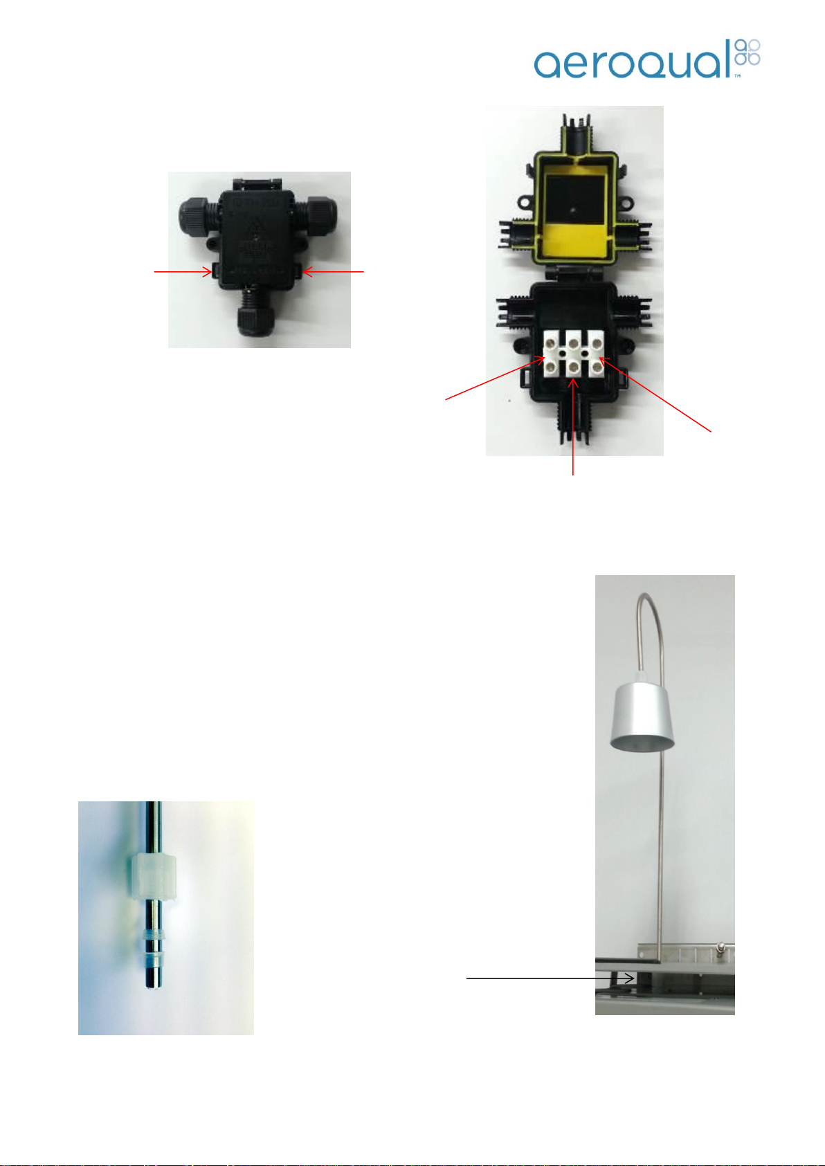
2.2.1. Connect Mains Power
Caution: The high voltage mains supply must be wired by a certified electrician in
compliance with local electrical regulations.
Locate the 3 port junction box on the outside of the AQM cabinet:
Unscrew from the enclosure
Remove the three gland nuts
Insert a small flat bladed screwdriver to lever the retaining clips, on each side where indicated
Wire a mains electrical cable to the terminal block provided (Live, Ground and Neutral).
Close the lid to the 3 port junction box and replace the three gland nuts.
Page | 17
Aeroqual AQM60 User Guide
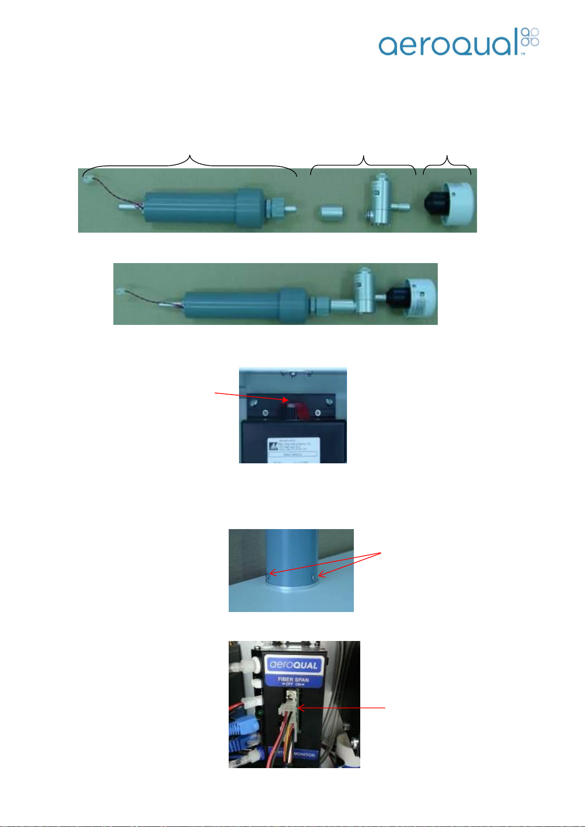
2.2.2. Connect Inlet Sub Assembly
Once the AQM60 has been connected the inlet sub assembly needs to be
installed to prevent unwanted materials, such as water and dust, being drawn into
the instrument. The sub assembly pipe is connected to the inlet at the top of the
AQM60 using a Kynar gland. The pipe needs to be securely inserted into the
Kynar gland and then the fitting needs to be tightened.
Ensure the two piece ferrule set is present inside the Kynar gland before screwing
it on, and be sure the orientation of the two pieces is correct as shown in the
image below. Failure to do this could result in a leak or could lead to water
entering the sample tubing which will permanently damage the sensor modules.
Kynar Gland
Neutral
(Blue)
Ground
(Green/Yellow)
Live
(Brown)
Retaining
clip
Retaining
clip
Page | 18
Aeroqual AQM60 User Guide
Power cable from
heated inlet
2.2.3. Assembly of heated inlet for PM/Profiler (Optional)
Parts List:
A. Inlet Tube/Heater including power cable
B. Sharp Cut Cyclone (if fitted)
C. TSP Inlet
i. Connect parts A, B and C
ii. Open door of enclosure and remove protective cap from the optical engine
iii. Insert Inlet Tube Assembly through base mount and fix the three mounting screws
Note 1: The top plate solar shield may need to be removed to screw in the mounting screws
Note 2: Ensure the power cable is fed through the inlet hole when connecting
iv. Connect power to Inlet Tube/Heater inside the enclosure
A
B
C
Mounting
Screws
Protective
Cap

Page | 19
Aeroqual AQM60 User Guide
2.2.4. Connect third party sensors (Optional)
Third party sensors such as the Vaisala Weather Transmitter WXT520 or Gill Windsonic are connected to
the unit using the external plug. This is located on the right hand side of the enclosure. Once connected, they
should automatically start reading.
Note: Turn off the AQM60 before plugging in any external third part sensor.
2.3. Initial Commissioning
The objective of the initial commissioning process is to enable the user to gain knowledge in the operation of
the instrument and to demonstrate that it is operating correctly prior to a remote installation. The process
consists of a set of tasks that check that the AQM is operating correctly.
Equipment required:
AQM Logbook
Computer with Aeroqual AQM V6.X PC software loaded
Flow meter covering the range 0-2.5 LPM
Zero air source
Span gases corresponding to the sensors in the AQM
Calibrator or gas flow meters for generating suitable span gas concentrations
Humidifier (Nafion tubing supplied with AQM)
Note 1: Before starting the commissioning process it is important that the AQM is fully warmed up by
running overnight and sampling either outside ambient air or indoor air with an activated carbon
filter connected to the inlet.
2.3.1. Set Up
1. Once the AQM60 is assembled and power is connected install the SD card into the control module.
Note 1: The TMS blower will start as soon as the mains power is connected.
2. Start the AQM60 by pushing the on/off switch on the control module (See Section 1.1 for location of
On/Off switch)
3. Connect the instrument using a computer via the USB cable to the outside of the enclosure
4. Install Aeroqual AQM software
5. Configure the AQM60 instrument:
a. Launch Aeroqual AQM PC software. Select Setup Communication Port
b. Select Serial Port RS232 and the relevant Com port. Press OK when complete.
Note: To determine the COM port number use windows ‘Device Manager’
The settings should be as seen below:
Page | 20
Aeroqual AQM60 User Guide
c. A table listing the modules configured will appear. Check the correct sensors in the AQM60
have been configured. These should match the sensors on the invoice and the sensors
listed in the instrument logbook. If they do not match click “Setup” ”Configuration” and
enter the password “Password”. Move across the relevant modules. Once completed press
“Save” then “Close” (See Section 3.2.2.).
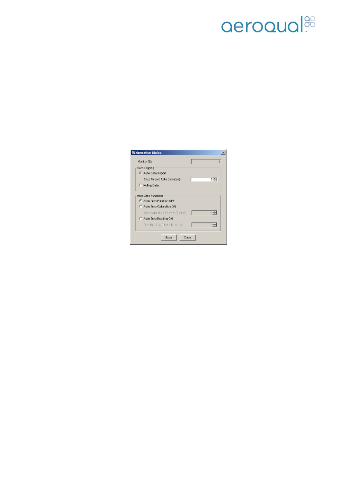
d. Select Setup Operations.
e. Enter Data Report Rate (2 minutes is the minimum) and select “Auto Zero Function OFF”
Click save and close to complete. Note that increasing the report time can cause problems
especially during calibration. (see later the section on calibration) It is recommended to leave
the logging frequency at 2 minutes, and to perform averaging at lower frequencies in
software such as Microsoft Excel.
6. Set AQM60 Real Time Clock
f. Click on Tools Update Real Time Clock (this will synchronise the AQM60 clock with the
computer date/time)
7. Start data-logging to confirm sensor communication and operation is correct.
g. Click Data Table Real Time to launch real time data table.
h. Click File Start Data logging. Data will start being displayed in Real Time Table.
2.3.2. System Checks
Controller display correct
With the AQM on, open the door and observe the display on the controller. This should be scrolling
with sensor readings.
TMS setting
Close the door to the AQM and wait for the internal temperature to stabilise.
Check (and record) that the internal temperature is stable and that it has reached the set point
defined in the logbook e.g. Set point = 30°C
SD card logging correct
Verify the AQM is data logging correctly to the SD card by clicking “File” “Download Files” in the
PC software.
A daily log file (DLYYMMDD.AQL) containing the AQM sensor data is created each day.
System events such as power on, configuration updates, calibration events and system faults are
logged to an EVENTLOG.AQL file.
Table of contents
Other Aeroqual Accessories manuals


