Aerospool WT-9 Dynamic Manual

LIMITEDCOMPANY
AEROSPOOLPRIEVIDZA
AirfieldPrievidza
971 03 PRIEVIDZA
SlovakRepublic
Fax:+421 46 5183 250
Tel.:+421 46 5183200
aerospool@aerospool.sk
www.aerospool.sk
TECHNICALDESCRIPTION
OPERATING, MAINTENANCE
AND REPAIRMANUAL
FORAEROPLANE
WT-9Dynamic
Type:WT-9Dynamic
Model:Allmodels
SerialNumber:DY-380/2010
Registration:S5-PIK
DateofIssue:19.08.2010
Owner:

Theaeroplanemanufacturerwillhighlyappreciateallsuggestiveproposalsand reminders
concerningthisManualaswellasanannouncementofknowledgeand experience found
duringWT-9Dynamicaeroplaneoperation.
Translationofthismanualhasbeendonebybestknowledgeand judgement.Inanycase
theoriginalinSlovaklanguageisauthoritative.

TECHNICALDESCRIPTION,OPERATING, MAINTENANCEAND REPAIRMANUAL
S ECTION0
G E N E R A L
Date: 01.03.2002 WT-9Dynamic Section0Page0-
1

TECHNICALDESCRIPTION,OPERATING, MAINTENANCEAND REPAIRMANUAL
0.1. RECORD OFREVISION
Anyrevisionsoramendmentstothismanualshallbeissuedintheformofbulletinswith
attachednewpages. Itisintheinterestsofeveryusertoentersuchrevisionintothetableof
revisionsandtoreplacetheexistingpagebythenewone.Therevisedorcorrectedtext
shall beindicatedbyaverticallineonpagefore-edgeandthepageshallbearrevision
numberanddateofitsissue.
Revision
Number Affected
Section Affected
Page Dateof
Issue Bulletin
No. Dateof
Approval Date
Inserted Signature
16, 8, 28, 241 3 11 07.02.2007
-- - - 07.02.2007
1 2, 11, 12, 19,
22, 23
2
3 19, 23 05.12.2007
-- - - 05.12.2007
3 0 2, 3 20.10.2008
ZBWT9
09A/2008 -- 20.10.2008
3 3 8 20.10.2008
ZBWT9
09A/2008 -- 20.10.2008
4 0 2, 3 05.10.2009
ZBWT9
11A/2009 -- 01.02.2010
4 1 24 05.10.2009 ZBWT9
11A/2009 -- 01.02.2010
4 3 14 05.10.2009 ZBWT9
11A/2009 -- 01.02.2010
5 0 2, 3 05.02.2010
-- - - 05.02.2010
5 1 22 05.02.2010
-- - - 05.02.2010
6 0 2, 3 30.05.2011
ZBWT9
12A/2010 -- 12.08.2011
6 3 3 30.05.2011
ZBWT9
12A/2010 -- 12.08.2011
7 0 2, 3 12.09.2011
ZBWT9
14A/2011 --
7 1 3, 6 12.09.2011
ZBWT9
14A/2011 --
7 3 3 12.09.2011
ZBWT9
14A/2011 --
Date: 12.09.11, Rev.7 WT-9Dynamic Section0Page0-2

TECHNICALDESCRIPTION,OPERATING, MAINTENANCEAND REPAIRMANUAL
0.2LISTOFEFFECTIVEPAGES
Section Page Date Section Page Date
0 0-1 01.03.2002 2 2-1 01.03.2002
0-2 12.09.2011 2-2 01.03.2002
0-3 12.09.2011 2-3 01.03.2002
0-4 01.03.2002 2-4 01.03.2002
0-5 01.03.2002 2-5 01.03.2002
2-6 01.03.2002
1 1-1 01.03.2002 2-7 01.03.2002
1-2 05.12.2007 2-8 01.03.2002
1-3 12.09.2011 2-9 01.03.2002
1-4 01.03.2002 2-10 01.03.2002
1-5 01.03.2002 2-11 01.03.2002
1-6 12.09.2011 2-12 01.03.2002
1-7 01.03.2002 2-13 01.03.2002
1-8 07.02.2007
1-9 01.03.2002 3 3-1 01.03.2002
1-10 01.03.2002 3-2 01.03.2002
1-11 05.12.2007 3-3 12.09.2011
1-12 05.12.2007 3-4 01.03.2002
1-13 01.03.2002 3-5 01.03.2002
1-14 01.03.2002 3-6 01.03.2002
1-15 01.03.2002 3-7 01.03.2002
1-16 01.03.2002 3-8 20.10.2008
1-17 01.03.2002 3-9 01.03.2002
1-18 01.03.2002 3-10 01.03.2002
1-19 05.12.2007 3-11 07.02.2007
1-20 01.03.2002 3-12 01.03.2002
1-21 01.03.2002 3-13 01.03.2002
1-22 05.02.2010 3-14 05.10.2009
1-23 05.12.2007 3-15 01.03.2002
1-24 05.10.2009 3-16 01.03.2002
1-25 01.03.2002 3-17 01.03.2002
1-26 01.03.2002 3-18 01.03.2002
1-27 01.03.2002 3-19 05.12.2007
1-28 07.02.2007 3-20 01.03.2002
1-29 01.03.2002 3-21 01.03.2002
1-30 01.03.2002 3-22 01.03.2002
1-31 01.03.2002 3-23 05.12.2007
3-24 01.03.2002
Date: 12.09.11, Rev.7 WT-9Dynamic Section0Page0-3

TECHNICALDESCRIPTION,OPERATING, MAINTENANCEAND REPAIRMANUAL
Section Page Date Section Page Date
4 4-1 01.03.2002
4-2 01.03.2002
4-3 01.03.2002
4-4 01.03.2002
4-5 01.03.2002
4-6 01.03.2002
5 5-1 01.03.2002
5-2 01.03.2002
5-3 01.03.2002
5-4 01.03.2002
5-5 01.03.2002
5-6 01.03.2002
5-7 01.03.2002
5-8 01.03.2002
5-9 01.03.2002
5-10 01.03.2002
5-11 01.03.2002
5-12 01.03.2002
Date: 01.03.2002 WT-9Dynamic Section0Page0-4

TECHNICALDESCRIPTION,OPERATING, MAINTENANCEAND REPAIRMANUAL
0.3 CONTENTS
Section
GENERAL0
TECHNICALDESCRIPTION1
OPERATION2
MAINTENANCE3
REPAIRS4
APPENDICES5
Date: 01.03.2002 WT-9Dynamic Section0Page0-5

TECHNICALDESCRIPTION,OPERATING, MAINTENANCEAND REPAIRMANUAL
SECTION1
TECHNICALDESCRIPTION
Page
1.1 Introduction1-3
1.2 Certificationbasis1-3
1.3 Warnings, cautionsandnotes1-3
1.4 Basicandgeneralinformation1-3
1.4.1Aeroplanedescription1-3
1.4.2 Designation1-3
1.5 Basictechnicaldata1-4
1.5.1Aeroplaneviews1-4
1.5.2Three-viewdrawing1-5
1.5.3Basicdimensions1-6
1.5.4Weights1-6
1.5.5Centreofgravity1-7
1.5.6Operatinglimitations1-7
1.6Technicaldescriptionoftheaeroplane1-7
1.6.1General1-7
1.6.2Fuselage1-7
1.6.3Wing1-7
1.6.3.1Aileron1-8
1.6.3.2WingFlap1-8
1.6.4Horizontaltailunit1-8
1.6.5Verticaltailunit1-8
1.6.6Landinggear1-8
1.6.6.1Fixedundercarriage1-8
1.6.6.2Retractableundercarriage1-9
1.6.6.3Nosewheelleg1-10
1.6.6.4Retractableundercarriagesystem1-11
1.6.6.5Wheelbrakessystem1-12
1.6.7Cockpit1-13
1.6.7.1Cockpitcontrol1-13
Date: 01.03.2002 WT-9Dynamic Section1Page1-1

TECHNICALDESCRIPTION,OPERATING, MAINTENANCEAND REPAIRMANUAL
1.6.7.2Cockpitcanopy1-14
1.6.8Equipment1-14
1.6.8.1Seatsand safetyharness 1-14
1.6.8.2Baggagecompartment1-14
1.6.8.3 Instrumentpanel1-15
1.6.8.3.1Powerplantinstruments1-16
1.6.8.3.2Avionics1-18
1.6.8.3.3Additionalequipment1-18
1.6.8.3.4Oxygensystem1-19
1.6.9 Controlsystem1-19
1.6.9.1Longitudinalcontrolsystem1-19
1.6.9.2Lateralcontrolsystem1-20
1.6.9.3Wingflapcontrolsystem1-21
1.6.9.4Directionalcontrolsystem1-22
1.6.9.5AutoPilotsystem1-22
1.6.10Powerplant1-23
1.6.10.1Briefdescription1-23
1.6.10.2Engine1-23
1.6.10.2.1Enginedescription1-23
1.6.10.2.2Technicaldata1-23
1.6.10.2.3 Operationlimitations1-24
1.6.10.2.4 Fuel1-24
1.6.10.2.5 Oil1-25
1.6.10.3Propeller1-25
1.6.10.4Enginebed1-26
1.6.10.4.1Enginebedforfixedundercarriage1-26
1.6.10.4.2Enginebedforretractableundercarriage1-26
1.6.10.5Enginecowlings1-27
1.6.10.6Enginelubricationsystem1-27
1.6.10.7Enginecoolingsystem1-27
1.6.10.8Aeroplanefuelsystem1-28
1.6.10.8.1Fueltank draining1-28
1.6.10.9Heating1-29
1.6.10.10Ventilation1-29
1.6.11Electricalsystem1-29
1.6.12Pitot–staticsystem1-30
1.6.13CableRetractorWinchwithGuillotine1-31
1.6.14Placards1-32
Date: 05.12.2007 Rev. 2 WT-9Dynamic Section1Page1-2

TECHNICALDESCRIPTION,OPERATING, MAINTENANCEAND REPAIRMANUAL
1.1 Introduction
TheTechnicalDescription,Operating,Maintenance andRepairManualforaeroplane
WT-9Dynamichasbeenpreparedtoprovidetheinformationforthesafeandefficient
operationofthisultralightaeroplane.
Thismanualcontainssupplementaldatasuppliedbytheaeroplanemanufacturer.
1.2 Certificationbasis
ThistypeofaircrafthasbeenapprovedinGermanybytheDeutscherAeroClube.V.
(DaeC)inaccordance withtheGermanCertificationRegulationsandAirworthiness
RequirementsforultralightaircraftoftheDaeC(BFUdesDaeC, Ausgabe10/95)and
theTypeCertificateNo.61179 hasbeenissuedon23.10.2001.
TheCivilAviationAuthoritiesofSlovakRepublicfollowing anapplicationby
AEROSPOOL, spol. sr. o.Prievidza andafterstudying thedocumentationPredpis
MDPT SRL8/ALU . P-ULL-1SRhasissuedtheTypeCertificateofAirworthiness
No.V-80/2004datedApril25th 2005 forTypeWT-9Dynamic
CategoryofAirworthiness : NormalwithMTOMup to472,5kg
1.3Warnings, cautions and notes
Thefollowing definitionsapplytowarnings, cautionsandnotesusedinthemanual.
WARNING
Meansthatthenon-observationofthecorrespondingprocedure
leadstoanimmediateorimportantdegradationoftheflight
safety.
CAUTION
Meansthatthenon-observationofthecorrespondingprocedure
leadstoaminorortoamoreorlesslongtermdegradationofthe
flightsafety.
NOTE
Drawstheattentiontoanyspecialitem, notdirectlyrelatedto
safetybutwhichisimportantorunusual.
1.4 Basicandgeneralinformation
1.4.1Aeroplanedescription
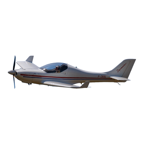
WT-9Dynamicisasingleengine,low-wingmonoplanewithtwoside-bysideseats
anddualcontrol.Anairframeconsistsofasandwichshellsfromadvancedcomposite
material.. Theaeroplaneisequippedwithafixedoraretractabletricycleundercarriage
withanosewheel.Aspowerplantofthisultralightaircraftisused4cylinder, 4stroke
enginesROTAX912 UL(59,6kW)orROTAX912 S2(73,5kW)with3blades,in
flightelectricallyadjustableaircraftpropellerWoodcompSR2000.
1.4.2 Designation
WT-9Dynamicisintendedforsporting, recreationandtouristflying inaccordance
withVFR. Aerobaticmanoeuvresandintentionalspinsareprohibited!
Date:
12.09.11, Rev.7
WT
-
9Dynamic
Section1Page1
-
3

TECHNICALDESCRIPTION,OPERATING, MAINTENANCEAND REPAIRMANUAL
1.5 Basictechnicaldata
1.5.1 Aeroplaneviews
Date:
01.03.2002
WT
-
9Dynamic
Section1Page1
-
4

TECHNICALDESCRIPTION,OPERATING, MAINTENANCEAND REPAIRMANUAL
1.5.2 Three-viewdrawing
Date: 01.03.2002 WT-9Dynamic Section1Page1-5

TECHNICALDESCRIPTION,OPERATING, MAINTENANCEAND REPAIRMANUAL
1.5.3 Basicdimensions
Wing
Wing span..…………...………………………………...
9,000 m
Wing area…............................................……………….
10,300 m2
Wing aspectratio.........................................……………
7,82
Aerodynamicmeanchord(MAC)……...……………..
1,185 m
Aileron
Aileronspan………………………………….…………
1,250 m
Aileronarea...………………………………………….. 0,273 m2
Wingflap
Flapspan..………………………………………………
2,280 m
Flaparea.………………………………………………..
0,750 m2
Fuselage
Length..…………………………………………………
6,400 m
Width..…………………………………………………. 1,180 m
Height…...……………………………………………...2,000 m
Horizontaltailunit
Horizontaltail span…...………………………………...
2,400 m
Horizontaltail area…………………………………….. 1,680 m2
Elevatorarea……………...…………………………….
0,500 m2
Verticaltailunit
Height.…………...………………………………….….1,022 m
Verticaltail area ………………………………………..
1,020 m2
Rudderarea………………..……………………………
0,360 m2
Landinggear
Wheelspacing……………………...…………………...
2,270 m
Wheelbase.……………………………………………..
1,490 m
Mainwheeldiameter………………………………….. 0,350 m
Nosewheeldiameter………………………………….. 0,320 m
1.5.4 Weights
Emptyweight
(withrescuesystemandstandardinstrumentequipment)
(ModelClub/Tow………………………………….. 279/298 kg
(ModelSpeed……………………………………… 299 kg
Maximumtake-offweight……..………………………………………
472,5kg
Maximumlanding weight……..………………………………………
472,5kg
Fuelweight(75 litres/optional100,5/126 litres…..……… 54/72,3/91kg
MaximumweightinBaggageCompartment………………… 10kg
Date:
12.09.11, Rev.7
WT
-
9Dynamic
Section1Page1
-
6

TECHNICALDESCRIPTION,OPERATING, MAINTENANCEAND REPAIRMANUAL
NOTE
Actualemptyweightisstatedontheplacard„LOADLIMITS„
stuckinthecockpit.
1.5.5 Centreofgravity
Emptyaeroplane.….………………………….
12 ±2%SAT
PositionofC.G. inflight…………………….. 20 ÷30%SAT
1.5.6 Operatinglimitations
RefertotheAeroplaneFlightManual(AFM), Section2formoredetailsaboutthe
followingoperatinglimits:
-Airspeedlimits,
-Weightslimits,
-C.G. rangelimits,
-Approvedmanoeuvres.
1.6Technicaldescriptionoftheaeroplane
1.6.1 General
Anairframeconsistsofasandwichshellsfromadvancedcompositematerial.The
shell is ofthree layerconstruction. Theexternaland internalshelllayersaremadeofa
glass andacarbonfiberfabricses,whicharesaturatedwitharesin.Betweenthem
thereisafilling fromahardfoampanels.Theshellsareformedinnegativeformsand
theyareheattreatmented12 hoursattemperature54 °Cforresin-harden.
1.6.2Fuselage
Thefuselagesandwichshellisdividedinthesymmetryplane.Thefuselagecross-
sectionareparaboliccurves.Thecockpitisreinforcementedwithhollowprofilefrom
advancedcompositematerial.Thebackrestofthecrewandthecentralpedestalare
gluedandtogetherwiththeshellstheycreatereinforcementelementoftheairframe.
Thefinismadetogetherwiththefuselage.Thewingcentralpanelisfixedatthe
fuselage.Thereistheintegraltankintheforwardboxofthewingcentralpanel.The
backboxofthewingcentralpanelisusedasroomformainlegsoftheretractable
undercarriage.Therearestiffening ribsinthebackboxofthewing centralpanelfor
grippingofthelegsofthefixedundercarriage.Arescuesystemwithejectionofthe
rescueparachutethroughremovablecovermaybelocatedbehind thefirewallofthe
powerplant. Ahorizontaltail isfixedatthefuselagetoo.Thebaggagecompartmentis
situatedbehind theseats.Thereistheframewiththeaccessholeintotherearpartof
thefuselage.ThePerspexcanopyisgluedonthecompositeframe.Thecanopyis
attachedtothenosesectionofthefuselagebypinswhichmakeitpossibleforthe
canopytobetiltedforward.Foreasiermanipulation,theweightofthecanopyis
counterbalancedbytwogasstrutswhichallowittoopeneffortlessly.Theengine
sectioninthenoseisseparatedfromthecockpitbyafirewallwhichtheenginebedis
attachedto.
Date:
01.03.2002
WT
-
9Dynamic
Section1Page1
-
7

TECHNICALDESCRIPTION,OPERATING, MAINTENANCEAND REPAIRMANUAL
1.6.3Wing
Aconstructionofthewing istwo–boxtype(themainsparcapsaremadefromthe
carbonrodsandoneauxiliarygirder).Atorsionboxisglassfibrereinforcedplastics
sandwichconstruction.Optionalyisinthefrontwingpartinstalledintegralfueltank
whichisconnectedwithcentralsectionfueltankwithsimplehouseconnectionwith
clamp.Thesparsofrightandleftwingsarejoinedtothewingcentralpanelsparwith
thehelpoftwopins.Theouterpinisinsertedthroughtheroomformainlegsofthe
retractableundercarriage(atmodelSPEED)orthroughtheaccessholeonthelower
wingsurface (atmodelCLUBandTOW).Theinnerpinisinsertedthroughthehole
inthecockpitbelowpilotseat.Thethirdjoinpointisthepinoftheauxiliarygirder.
ThePitot-staticheadislocatedontherightwingleadingedge.
1.6.3.1Aileron
Aconstructionoftheaileronisthesandwichshellstructuretype.Theaileronis
attachedtotheuppersurfaceofthewing shellwiththree hingesfromadvanced
compositematerial. Themovementbymeansoftherodistransmittedintotherootrib.
Thecontrol-surface weightbalance isattachedontheailerontiprib. Thedeflectionsof
theaileronsaredifferentiated1:1,6.
1.6.3.2 Wingflap
Thewing flapistheslottedflaptype,withthelowlying pointofrotation.A
constructionofthewing flapisthesandwichshellstructuretype. Theflapisattached
tothewingwithfourhinges.Themovementbymeansoftherodistransmittedinto
thewingflaprootrib.Theflapcontrolleverhasfourpositions:retracted,take-off
withflapdeflection15°,landing positionwithflapdeflection24 °andlanding
positionwithflapdeflection35°.
1.6.4 Horizontaltailunit
Thehorizontaltail unitconsistsofastabilizerand elevator.Thestabilizerconsistsof
thesandwichshellsfromadvancedcompositematerial.Thestabilizerisfixedatthe
fin.Theelevatorconsistsoftwoparts,whicharejoinedtogetherbymeansofthe
elevatorcontrol.Thecontrol-surface weightbalance areattachedonthetipofboth
parts oftheelevator.
1.6.5 Verticaltailunit
Theverticaltailunitconsistsofthefinandrudderandhastrapezoidalshape.Thefin
isanintegralpartofthefuselagerearsection. Therudderconsistsofasandwichshells
fromadvancedcompositematerialwiththecontrol-surface weightbalance.Theruder
isattachedbythree hingesatthefin.
1.6.6 Landinggear
WT-9Dynamic,modelClubandTowisequippedwithfixedtricyclelanding gearand
modelSpeedisequippedwithretractabletricyclelanding gear,whichisactuatedbya
hydraulicsystembythehelpoftheelectricaldrivenhydraulicpump.
1.6.6.1Fixedundercarriage
Themainlandinggearusesthelegs,whichareformedasafibber-glassspringsand
arefixedinthefuselagecasing undertheseatsonthestiffening ribsinthebackboxof
thewingcentralpanel.Thediameterofthemainwheelsis350 mm andtheyare
coveredwithlaminatedfairings.Themainwheelsonbothlegsareequippedwith
hydraulicdiscbrakes.Themainwheelarebrakedbyhydraulicbrakeswithmain
hydraulicface ram,whichislocatedbeyondtheseats.Themainwheelbrakesare
Date:
07.02.2007
Rev. 1
WT
-
9Dyn
amic
Section1Page1
-
8

TECHNICALDESCRIPTION,OPERATING, MAINTENANCEAND REPAIRMANUAL
actuatedviathehandleonthepedestalbetweenthepilotseats.Thishandleactuates
theparkingbraketoo. Systemsareactuatedviathehandleonthepedestalbetweenthe
pilotseats.Thenosewheellegconsistsofthesteeltubeandthecarbonfork,whereis
locatednosewheelwithdiameter300 mm.Thenosewheellegissupportedon
bearings(upperanddown)andiscontrolledbymeansoftherodsconnectedtothe
rudderpedals.Thespringing iscarriedoutwithrubberropeandwiththeflexible
element,whichislocatedintheuppernosewheelbearing.Thenosewheeliscovered
withlaminatedfairing.
1.6.6.2Retractableundercarriage
Mainundercarriage(Fig.2)consistsoftheweldedsteelleg(B), thearm(R)withthe
wheelandtheflexibleelement(FB).Themainlegisfixedintothefittingofthe
wingcentralpanelmainsparinfront, andintothefittingoftheauxiliarygirderinrear.
Thewheelisequippedwithdiscbrake(SB).Theretractionoftheundercarriageis
carriedoutwithhelpofthehydraulicface ramsinsidetothesymmetryplaneofthe
aeroplane.Thepistonsofthehydraulicface ramsareconnectedwiththedragstay,
whichisequippedwiththespiralspring (F). Thisspringpushesthedragstayduring
oftheundercarriageextensionintothearrestedposition.Theemergencyextensionof
theundercarriageiscarriedoutbyownmasswiththehelpathree-wayvalve. Thedrag
stayisarrestedwithhelpofthesprings.
Fig. 2Mainlegoftheretractableundercarriage
Date:
01.03.2002
WT
-
9Dynamic
Section1Page1
-
9
B
F
FB R
SB

TECHNICALDESCRIPTION,OPERATING, MAINTENANCEAND REPAIRMANUAL
1.6.6.3Nosewheelleg
Thenosewheellegoftheretractableundercarriage(Fig.3)position(B)isfixedinto
theenginebed. Thenosewheellegisthewheelarmtowedtype.
Thedamping ofthearmiscarriedoutwiththeflexibleelementsfrompolyurethane,
whicharelocatedinthetubeoftheleg(B).Thenoseundercarriagelegisretracted
backwards.Thedragstay(KS),whichisconnectedwiththepistonofthehydraulic
face ramprovidesforthemovementofthenoseundercarriage.Thegasstrut(GF)
providesfortheemergencyextensionofthenoseundercarriage.Thisgasstrut
extrudesthedragstayintothearrestedposition.
Thecontrolofthenoseundercarriagelegiscarriedoutwithhelpofthecontrolcables
(KZ)„Cabelcraft“typeconnectedwiththerudderpedals.
Fig.3Thenosewheellegoftheretractableundercarriage
Fig.4Settingofadragstay(KS
Date:
01.03.2002
WT
-
9Dynamic
Section1Page1
-
10
B
KZ
GF
KS

TECHNICALDESCRIPTION,OPERATING, MAINTENANCEAND REPAIRMANUAL
1.6.6.4Retractableundercarriagesystem
Fig.5Thehydraulicsystemschemeoftheretractableundercarriage
CAUTION
IncasethattheHydraulicpumpindicationlight(17)isshining formorethan20 secondsswitchoff
theHydraulicpumpcircuitbreaker(15).Thecontinuesrunning ofhydraulicpumpwillcauses
damageofhydraulicsystem.Thiscanbecausedoflooseofhydraulicpressurebecauseofhose
leakingorotherresson.Flywithextendedundercarriageandafterlanding contactauthorised
technicantofind andsolvetheproblem.
ThepowerissuppliedfromthebatterytotheoverswitchS1intheup positiononthe
instrumentpanellabelled“HydraulicOn”,whichswitchonthehydraulicpumpby
meansofthepressureswitchandtherelay. Thepressureswitchswitchesoff thepower
afterreaching ofdesiredpressure.TheoverswitchS1inthedownpositionlabelled
“EmergencyextensionofL/G”switchesontheemergencyextensionofthe
undercarriage.Theemergencyextensionoftheundercarriageiscarriedoutbyown
mass withthehelpathree-wayvalve.Thedragstayisarrestedwithhelpofthe
springs. TheotheroverswitchS2controlsthedirectionofthepressurefluidmovement
forextensionorretractionoftheundercarriage.Thepressurefluidproceedsviathe
three-wayvalvetotheoneoranothersideofthehydraulicface ram.Bothsidesofthe
hydraulicfaceramarewithoutpressureattheemergencyextensionofthe
undercarriage.
Date:
05.12.2007
Rev. 2
WT
-
9Dynamic
Section1Page1
-
11

TECHNICALDESCRIPTION,OPERATING, MAINTENANCEAND REPAIRMANUAL
1.6.6.5Wheelbrakesystem
Bothwheelsonmainundercarriageareequippedwiththehydraulicdiscbrakes.The
brakediscisboltedontheriminnerpartwiththree screws.Thehydraulicbrake
cylindersareactuatedwiththepressureofthehydraulicfluid.Thesource ofthe
pressureisthemainbrakehydraulicface ram,whichislocatedunderpilotseat-
standardorincetraltunnelBeringerbrakes.Themainbrakehydraulicfaceramis
actuatedviathehandlethepilotseats.Themovementoftheleveristransmittedto
mainbrakecylinder. Thepressurefluidisdistributedthroughthehoses.
Thishandleactuatestheparkingbraketoo.
Fig.6BrakesystemschemeforstandardandoptionalBeringerbrakesystem.
Date: 05.12.2007 Rev. 2 WT-9Dynamic Section1Page1-12

TECHNICALDESCRIPTION,OPERATING, MAINTENANCEAND REPAIRMANUAL
1.6.7Cockpit
Thesidewalloftheseatstogetherwiththepedestalbetweentheseatsandaback
supporteroftheseatsaregluedintothefuselageconstructionastheframe.Theseats
withathinupholsteryinteriorcockpitsidesarecoveredwithpaddedpanelswith
pockets. Thebottomoftheseatsareremovablefortheaccesstotheaggregates, which
aremountedbelowtheseats.
1.6.7.1Cockpitcontrol
Thecontrolsticksaresupportedonthetorsionaltube.Theattachmentsofthis
torsionaltubearefixedtothemainsparofthewingcentralpanel.Theflapcontrol
lever,elevatortrimtableverandthemainwheelbrakeshandlearelocatedonthe
pedestalbetweenthepilotseats.
Thestandardinstrumentpanelarrangementisshowninthefollowing figure.
Instrumentpanelarrangementisdescribedinpar.1.6.8.3.
pedestalbetweenthepilotseats.
Thestandardcockpitarrangementisshowninthefollowing figure.Instrumentpanel
arrangementisdescribedinpar. 1.6.8.3.
Fig.7. Cockpitarrangement
1. Control stick9.Instrumentpanel
2. Rudderpedals10.Ventilationslidingwindow
3. Elevatortrimcontrollever11.Ventilationflow baffle
4. Brakecontrollever12.Fueltank selector
5. Wingflapscontrollever13. Chockandthrottlelever
6. Pocket14.Ignition,Starterkey, Master
7. Headsetsocket/ jack15.GPS,Radio,Transponder
8.Seatandsafetybelt 16.Powerplantinstruments
17.Flightinstruments
Date:
01.03.2002
WT
-
9Dynamic
Section1Page1
-
13
1
3
2
4
5
6
7
8
9
10
11
12
13
14
4
15
16
17
Other manuals for WT-9 Dynamic
2
Table of contents
Other Aerospool Aircraft manuals
