PSA CRJ-900 User manual

**ON A/C 10003, 10040, 10043, 10046, 10048, 10052, 10063, 10076, 10080, 10083, 10085−10086, 10089,
10091, 10093, 10096, 10098, 10100, 10103, 10118, 10120, 10127, 10132−10139, 10141, 10143−10146,
10148−10151, 10153, 10155−10339, 15026−15316, 15317−15999
and ON A/C 10004−10039, 10041−10042, 10044−10045, 10047, 10049−10051, 10053−10062,
10064−10075, 10077−10079, 10081−10082, 10084, 10087−10088, 10090, 10092, 10094−10095, 10097,
10099, 10101−10102, 10104−10117, 10119, 10121−10126, 10128−10131, 10140, 10142, 10147, 10152,
10154, 15001−15025 Post SB670BA−34−009
TASK 34−54−00−720−802−PSA
Functional Test of the ATC Altitude Reporting (Mode C)
1. General
A. The maintenance procedure that follows is for the functional test of the altitude reporting (Mode
C). The transponder 1 is installed on the left side of the main avionics compartment . The
transponder 2 is installed on the right side of the main avionics compartment. This procedure is
applicable to the transponder 1 and transponder 2.
2. Job Set−Up Information
A. Tools and Equipment
REFERENCE DESIGNATION
ATC−601 (FUTURE
PROCUREMENT P/N IFR 6000)
Test Set −Transponder Mode S
IFR 6000 Ramp Test Set (Transponder, TCAS, DME)
ADTS405F Test Set −Air Data
ADCRJ−612 Connector Kit −Pitot Static Pressure Test
B. Reference Information
MANUAL NO REFERENCE DESIGNATION
CSP−B−001 TASK 12−00−00−867−801 Standard Aircraft Configuration for Maintenance
CSP−B−001 TASK 24−00−00−861−801 Connect Electrical Power to the Aircraft
CSP−B−001 TASK 24−00−00−861−802 Remove Electrical Power from the Aircraft
CSP−B−001 TASK 24−00−00−910−801 Electrical/Electronic Safety Precautions
CSP−B−001 TASK 32−61−00−867−801 Put the Aircraft in a Weight−Off−Wheels Configuration
with the Aircraft on Ground
CSP−B−001 TASK 32−61−00−867−802 Remove the Aircraft From the Weight−Off−Wheels
Configuration with the Aircraft on Ground
Internal PSA Document
CRJ-900
AIRCRAFT MAINTENANCE MANUAL
PSA AIRLINES, INC REVISION
EFFECTIVITY: Ref page 1 of Blue Page
34-54-00-720-802-PSA Rev A
AMM - Insert after Task 34-54-00-720-802-A01 of AMM 34-54-00
Remove Rev 34-54-00-720-802PSA dated Sep 17/14 and insert 34-54-00-720-802-PSA Rev A dated 10/12/15
10/12/15
Page 1 of 13

3. Job Set−Up
WARNING: MAKE SURE THAT THE AIRCRAFT STAYS IN A WEIGHT−ON−WHEELS (WOW)
CONDITION AT ALL TIMES. A WEIGHT−OFF−WHEELS CONDITION CAN CAUSE
INCORRECT TCAS ADVISORIES ON AIRCRAFT THAT OPERATE IN THE AREA.
A. Make sure that the aircraft is in the standard configuration for maintenance
(TASK 12−00−00−867−801).
B. Obey all the electrical/electronic safety precautions (TASK 24−00−00−910−801).
C. Connect the electrical power to the aircraft (TASK 24−00−00−861−801).
WARNING: OPEN, SAFETY, AND TAG THE CIRCUIT BREAKERS FOR THE HEATERS OF
THE PITOT−STATIC SYSTEM. THE AIR DATA SENSORS CAN GET VERY HOT
AND CAUSE BURNS.
D. Open and tag the circuit breakers that follow:
CB−PANEL CB−NO NAME
CBP−1 A12 HEATERS TAT
CBP−1 A13 HEATERS AOA R
CBP−1 A14 HEATERS PITOT R
CBP−1 G14 HEATERS STATIC R
CBP−1 Q2 STALL PROT L CH
CBP−1 LOWER T7 HEATERS PITOT L
CBP−1 LOWER T8 HEATERS AOA L
CBP−1 LOWER T9 HEATERS PITOT STBY
CBP−1 LOWER V10 TCAS
CBP−2 H8 XPDR 2
CBP−2 LOWER S1 HEATERS STATIC L
CBP−2 LOWER U5 STALL PROT R CH
CBP−2 LOWER V5 XPDR 1
Refer to Figure 503
E. If you use ATC−601 test set, prepare the test set as follows:
(1) Move all large metal objects located in a 180 degree arc in front of the ATC antenna to a
distance of 40 feet away from the antenna.
(2) Install the test antenna on a tripod.
Internal PSA Document
CRJ-900
AIRCRAFT MAINTENANCE MANUAL
PSA AIRLINES, INC REVISION
EFFECTIVITY: Ref page 1 of Blue Page
34-54-00-720-802-PSA Rev A
AMM - Insert after Task 34-54-00-720-802-A01 of AMM 34-54-00
Remove Rev 34-54-00-720-802PSA dated Sep 17/14 and insert 34-54-00-720-802-PSA Rev A dated 10/12/15
10/12/15
Page 2 of 13

(3) Move the tripod 10±1 feet (3±0.30 m) in front of and in line with the bottom right antenna
(ATC 1).
(4) Connect the test set antenna to the test set.
(5) Make sure that the covers are installed on all the unused connectors.
(6) Install the antenna shields on the top left antenna (ATC 1) and the top right antenna (ATC
2).
(7) On the test set, push the POWER key.
(8) Push the SELF TEST key to start the self−test.
(9) At the end of the self−test, make sure the test set display is as follows:
– ** SELF TEST −PASSED **
– RF MODULE: PASSED
– DIGITAL MODULE: PASSED
– POWER SUPPLY/BATTERY: PASSED.
(10) Push the SETUP key and make sure that the SETUP MENU is shown.
(11) On the SETUP MENU, make the selections that follow:
NOTE: Use the SELECT keys to change the fields and the SLEW keys to change the
field values.
(a) Set the antenna selection to the bottom antenna.
(b) Set the top antenna range to 15 feet.
(c) Set the bottom antenna range to 10 feet.
(d) Set the GAIN 1030 and GAIN 1090 indications to the values shown on the test
antenna.
(e) Set the LOSS indication to the value shown on the test antenna coax cable.
F. If you use IFR 6000 test set, prepare the test set as follows:
NOTE: Refer the manufacturer’s instructions to use the IFR 6000 test set.
NOTE: Do not operate the IFR 6000 test set in the diagnostic mode while the test antenna is
connected. Signal could interfere with air traffic control facilities or aircraft in the area.
(1) Move all large metal objects located in a 180 degree arc in front of the transponder antenna
to a distance of 40 feet (12.19 m) away from the antenna.
Internal PSA Document
CRJ-900
AIRCRAFT MAINTENANCE MANUAL
PSA AIRLINES, INC REVISION
EFFECTIVITY: Ref page 1 of Blue Page
34-54-00-720-802-PSA Rev A
AMM - Insert after Task 34-54-00-720-802-A01 of AMM 34-54-00
Remove Rev 34-54-00-720-802PSA dated Sep 17/14 and insert 34-54-00-720-802-PSA Rev A dated 10/12/15
10/12/15
Page 3 of 13

(2) Put a tripod or an equivalent stand, approximately 30 feet (9.14 m) in a line−of−sight with
the ATC 1 antenna (top left).
NOTE: The ATC 1 antennas are E14 (bottom right) and E15 (top left). The ATC 2
antennas are E17 (bottom left) and E16 (top right).
(3) Install the test set with the antenna on the tripod.
(4) Adjust the tripod until the antenna is approximately 5 feet (1.52 m) above the ground.
(5) Align the test antenna azimuth and tilt to point directly at the ATC 1 antenna (top left).
(6) Connect the test antenna to the test set using the short RF coaxial cable.
(7) Install an antenna shield on the bottom right antenna (ATC 1) and the bottom left antenna
(ATC 2).
(8) Push the POWER key.
(9) Make sure that the test set powers up and does the self test.
(10) After the self test, push the SETUP key until you get the SETUP−XPDR screen.
(11) On the SETUP−XPDR screen, set the parameters as follow:
NOTE: Use the NEXT PARM and PREV PARAM soft keys to select the parameters. Use
DATA keys to slew the data in the DATA FIELD for the selected parameters.
– ANTENNA : TOP
– RF PORT : ANTENNA
– ANT RANGE TOP : 31 ft (9.45 m)
– ANT RANGE BOTTOM : 30 ft (9.14 m)
– ANT CABLE LOSS: Set to the figure marked on the test antenna RF cable
– ANT GAIN: Set to the figure marked on the test antenna
– UUT ADDRESS: AUTO
– DIVERSITY: ON
– CHECK CAP: YES
– PWR LIM: FAR 43.
(12) On the test set, push the XPDR key to display the XPDR−AUTO TEST screen.
(13) On the XPDR−AUTO TEST screen, push the CONFIG soft key to display the
XPDR−CONFIG screen.
(14) Use DATA key to select GENERIC MODE S as the configuration file on the XPDR−CONFIG
screen.
Internal PSA Document
CRJ-900
AIRCRAFT MAINTENANCE MANUAL
PSA AIRLINES, INC REVISION
EFFECTIVITY: Ref page 1 of Blue Page
34-54-00-720-802-PSA Rev A
AMM - Insert after Task 34-54-00-720-802-A01 of AMM 34-54-00
Remove Rev 34-54-00-720-802PSA dated Sep 17/14 and insert 34-54-00-720-802-PSA Rev A dated 10/12/15
10/12/15
Page 4 of 13

(15) Push the RETURN key to display the XPDR−AUTO TEST screen.
CAUTION: MAKE SURE THAT THE PITOT AND STATIC INPUTS ARE DECREASED TO
AMBIENT BEFORE YOU CONNECT OR DISCONNECT AN INPUT. DAMAGE TO
THE AIRCRAFT INSTRUMENTS CAN OCCUR.
G. Prepare the air data test set (ADTS) for the test as follows:
(1) Install the pitot−static adaptors on the P1 and P2 pitot−static heads.
NOTE: Refer to the manufacturer instructions for the pitot−static test adapters when you
install the adapters.
(2) On the P1 pitot−static head, do as follows:
(a) Connect the pitot test hose assembly to the P1 pitot−pressure input.
(b) Connect the static test hose assemblies to the S1 and S2 static−pressure inputs.
(3) On the P2 pitot−static head, do as follows:
(a) Connect the pitot test hose assembly to the P2 pitot−pressure input.
(b) Install caps on the S1 and S2 static−pressure inputs.
H. Prepare the flight compartment as follows:
(1) On the tuning select panel, set the ATC SEL switch to STBY.
(2) Remove the tag and close the circuit breaker that follows:
CB−PANEL CB−NO NAME
CBP−2 LOWER V5 XPDR 1
(3) On the source select panel, set the AIR DATA switch to NORM.
(4) On the air data reference panels (ARP) 1 and ARP 2, push the PUSH STD pushbutton.
(5) On the primary flight displays (PFD) 1 and PFD 2, make sure the barometric pressure
shows 29.92 inHg (101.32 kPa).
(6) On the RTU 1 and RTU 2, make the selections that follow on the ATC pages:
(a) Set the ALT ON.
(b) Make sure the altitude shows 200 ft or less above field elevation.
(c) Call the ATC and set the ATC to the local airport code.
Internal PSA Document
CRJ-900
AIRCRAFT MAINTENANCE MANUAL
PSA AIRLINES, INC REVISION
EFFECTIVITY: Ref page 1 of Blue Page
34-54-00-720-802-PSA Rev A
AMM - Insert after Task 34-54-00-720-802-A01 of AMM 34-54-00
Remove Rev 34-54-00-720-802PSA dated Sep 17/14 and insert 34-54-00-720-802-PSA Rev A dated 10/12/15
10/12/15
Page 5 of 13

(7) Put the aircraft in a Weight−Off−Wheels configuration (TASK 32−61−00−867−801).
4. Procedure
CAUTION: MAKE SURE THAT THE RTU ATC CODE IS NOT SET TO 7500, 7600, 7700, OR
7777 WHILE POWER IS SUPPLIED TO THE TRANSPONDER(S). IF THESE CODES
ARE RECEIVED BY A LOCAL ATC AUTHORITY, THEY WILL THINK THE
AIRCRAFT IS IN AN EMERGENCY CONDITION.
A. If you use ATC−601 test set, do the functional test of the transponder system as follows :
(1) Do the test of the ATC 1 transponder as follows:
(a) On the ADTS, slowly adjust the altitude control to get −1000 feet.
NOTE: Let the altitude become stable for one minute.
(b) On the tuning select panel, set the ATC SEL switch to 1.
NOTE: The ATC must transmit for only 10 seconds and stay off for 30 seconds
between transmissions during the steps that follow.
(c) On the ATC test set, push the AUTO TEST key and go to the ** MODE S UF0 TEST
**.
(d) Make sure the altitude shown on the ATC test set is the same as the altitude shown on
the PFD 1 ±125 feet.
(e) Record the PFD 1 and ATC test set values in the table below.
ADTS ALTITUDE (FEET) PFD 1 (FEET) ATC TEST SET (FEET)
−1000
0
1000
10000
22000
33000
41000
(f) On the tuning select panel, set the ATC SEL switch to STBY.
(g) Do the steps that follow for each altitude in the table above:
Internal PSA Document
CRJ-900
AIRCRAFT MAINTENANCE MANUAL
PSA AIRLINES, INC REVISION
NOTE:When using the ATC−601 test set, the RUN/STOP key or Test Antenna test button
must be selected to initiate the “MODE S UF0 TEST”. To terminate the test, select the
RUN/STOP key or Test Antenna test button, then re-select the RUN/STOP key or Test
Antenna test button to re-initiate the test for the next altitude check.
34-54-00-720-802-PSA Rev A
AMM - Insert after Task 34-54-00-720-802-A01 of AMM 34-54-00
Remove Rev 34-54-00-720-802PSA dated Sep 17/14 and insert 34-54-00-720-802-PSA Rev A dated 10/12/15
10/12/15
Page 6 of 13
EFFECTIVITY: Ref page 1 of Blue Page

2On the tuning select panel, set the ATC SEL switch to 1.
NOTE: The ATC must transmit for only 10 seconds and stay off for 30
seconds between transmissions during the steps that follow.
3 Make sure the altitude shown on the ATC test set is the same as the altitude
shown on the PFD 1 ±125 feet.
4 Record the PFD 1 and ATC test set values in the table above.
5 On the tuning select panel, set the ATC SEL switch to STBY.
(h) Open and tag the circuit breaker that follows:
CB−PANEL CB−NO NAME
CBP−2 LOWER V5 XPDR 1
(2) Do the test of the ATC 2 transponder as follows:
(a) Move the tripod 10±1 feet (3±0.30 m) in front of and in line with the bottom left antenna
(ATC 2).
(b) Remove the tag and close the circuit breaker that follows:
CB−PANEL CB−NO NAME
CBP−2 H8 XPDR 2
(c) On the ADTS, slowly adjust the altitude control to get −1000 feet.
NOTE: Let the altitude become stable for one minute.
(d) On the tuning select panel, set the ATC SEL switch to 2.
NOTE: The ATC must transmit for only 10 seconds and stay off for 30 seconds
between transmissions during the steps that follow.
(e) On the ATC test set, push the AUTO TEST key and go to the ** MODE S UF0 TEST
**.
(f) Make sure the altitude shown on the ATC test set is the same as the altitude shown on
the PFD 2 ±125 feet.
(g) Record the PFD 2 and ATC test set values in the table below.
Internal PSA Document
CRJ-900
AIRCRAFT MAINTENANCE MANUAL
PSA AIRLINES, INC REVISION
EFFECTIVITY: Ref page 1 of Blue Page
34-54-00-720-802-PSA Rev A
AMM - Insert after Task 34-54-00-720-802-A01 of AMM 34-54-00
Remove Rev 34-54-00-720-802PSA dated Sep 17/14 and insert 34-54-00-720-802-PSA Rev A dated 10/12/15
10/12/15
Page 7 of 13
On the ADTS, slowly adjust the altitude control to go to each altitude.
NOTE: Let the altitude become stable for one minute.
1
ADTS ALTITUDE (FEET) PFD 2 (FEET) ATC TEST SET (FEET)
−1000
0
1000
10000
22000
33000
41000
(h) On the tuning select panel, set the ATC SEL switch to STBY.
(i) Do the steps that follow for each altitude in the table above:
1 On the ADTS, slowly adjust the altitude control to go to each altitude.
NOTE: Let the altitude become stable for one minute.
2 On the tuning select panel, set the ATC SEL switch to 2.
NOTE: The ATC must transmit for only 10 seconds and stay off for 30
seconds between transmissions during the steps that follow.
(j) Make sure the altitude shown on the ATC test set is the same as the altitude shown on
the PFD 2 ±125 feet.
(k) Record the PFD 2 and ATC test set values in the table above.
(l) On the tuning select panel, set the ATC SEL switch to STBY.
(m) Open and tag the circuit breaker that follows:
CB−PANEL CB−NO NAME
CBP−2 H8 XPDR 2
B. If you use IFR 6000 test set, do the functional test of the transponder system as follows:
(1) Do the test with the ATC 1 transponder as follows:
(a) On the ADTS, slowly adjust the altitude control to get −1000 feet.
NOTE: Let the altitude become stable for one minute.
Internal PSA Document
CRJ-900
AIRCRAFT MAINTENANCE MANUAL
PSA AIRLINES, INC REVISION
EFFECTIVITY: Ref page 1 of Blue Page
34-54-00-720-802-PSA Rev A
AMM - Insert after Task 34-54-00-720-802-A01 of AMM 34-54-00
Remove Rev 34-54-00-720-802PSA dated Sep 17/14 and insert 34-54-00-720-802-PSA Rev A dated 10/12/15
10/12/15
Page 8 of 13

(b) On the tuning select panel, set the ATC SEL switch to 1.
NOTE: The ATC must transmit for only 10 seconds and stay off for 30 seconds
between transmissions during the steps that follow.
(c) On the IFR 6000 test set, select XPDR−UFO from the XPDR−TEST LIST screen.
NOTE: You can use TEST LIST softkey from auto test screen to select a required
test, push SELECT TEST soft key and then push RUN TEST soft key.
(d) Push the RUN TEST soft key to run XPDR−UFO test.
(e) Make sure the altitude shown on the IFR 6000 test set is the same as the altitude
shown on the PFD 1 ±125 feet.
(f) Record the PFD 1 and IFR 6000 test set values in the table below.
ADTS ALTITUDE (FEET) PFD 1 (FEET) IFR 6000 TEST SET (FEET)
−1000
0
1000
10000
22000
33000
41000
(g) On the tuning select panel, set the ATC SEL switch to STBY.
(h) Do the steps that follow for each altitude in the table above:
1 On the ADTS, slowly adjust the altitude control to go to each altitude.
NOTE: Let the altitude become stable for one minute.
2 On the tuning select panel, set the ATC SEL switch to 1.
NOTE: The ATC must transmit for only 10 seconds and stay off for 30
seconds between transmissions during the steps that follow.
3 Make sure the altitude shown on the IFR 6000 test set is the same as the altitude
shown on the PFD 1 ±125 feet.
4 Record the PFD 1 and IFR 6000 test set values in the table above.
5 On the tuning select panel, set the ATC SEL switch to STBY.
Internal PSA Document
CRJ-900
AIRCRAFT MAINTENANCE MANUAL
PSA AIRLINES, INC REVISION
EFFECTIVITY: Ref page 1 of Blue Page
34-54-00-720-802-PSA Rev A
AMM - Insert after Task 34-54-00-720-802-A01 of AMM 34-54-00
Remove Rev 34-54-00-720-802PSA dated Sep 17/14 and insert 34-54-00-720-802-PSA Rev A dated 10/12/15
10/12/15
Page 9 of 13
(i) Open and tag the circuit breaker that follows:
CB−PANEL CB−NO NAME
CBP−2 LOWER V5 XPDR 1
(2) Do the test with the ATC 2 transponder as follows:
(a) Move the tripod 10±1 feet (3±0.30 m) in front of and in line with the bottom left antenna
(ATC 2).
(b) Remove the tag and close the circuit breaker that follows:
CB−PANEL CB−NO NAME
CBP−2 H8 XPDR 2
(c) On the ADTS, slowly adjust the altitude control to get −1000 feet.
NOTE: Let the altitude become stable for one minute.
(d) On the tuning select panel, set the ATC SEL switch to 2.
NOTE: The ATC must transmit for only 10 seconds and stay off for 30 seconds
between transmissions during the steps that follow.
(e) On the IFR 6000 test set, select XPDR−UFO from the XPDR−TEST LIST screen.
NOTE: You can use TEST LIST softkey from auto test screen to select a required
test, push SELECT TEST soft key and then push RUN TEST soft key.
(f) Push the RUN TEST soft key to run XPDR−UFO test.
(g) Make sure the altitude shown on the IFR 6000 test set is the same as the altitude
shown on the PFD 2 ±125 feet.
(h) Record the PFD 2 and IFR 6000 test set values in the table below.
ADTS ALTITUDE (FEET) PFD 2 (FEET) IFR 6000 TEST SET (FEET)
−1000
0
1000
10000
22000
33000
Internal PSA Document
CRJ-900
AIRCRAFT MAINTENANCE MANUAL
PSA AIRLINES, INC REVISION
EFFECTIVITY: Ref page 1 of Blue Page
34-54-00-720-802-PSA Rev A
AMM - Insert after Task 34-54-00-720-802-A01 of AMM 34-54-00
Remove Rev 34-54-00-720-802PSA dated Sep 17/14 and insert 34-54-00-720-802-PSA Rev A dated 10/12/15
10/12/15
Page 10 of 13

ADTS ALTITUDE (FEET) PFD 2 (FEET) IFR 6000 TEST SET (FEET)
41000
(i) On the tuning select panel, set the ATC SEL switch to STBY.
(j) Do the steps that follow for each altitude in the table above:
1 On the ADTS, slowly adjust the altitude control to go to each altitude.
NOTE: Let the altitude become stable for one minute.
2 On the tuning select panel, set the ATC SEL switch to 2.
NOTE: The ATC must transmit for only 10 seconds and stay off for 30
seconds between transmissions during the steps that follow.
3 Make sure the altitude shown on the IFR 6000 test set is the same as the altitude
shown on the PFD 2±125 feet.
4 Record the PFD 2 and IFR 6000 test set values in the table above.
5 On the tuning select panel, set the ATC SEL switch to STBY.
(k) Open and tag the circuit breaker that follows:
CB−PANEL CB−NO NAME
CBP−2 H8 XPDR 2
5. Close Out
A. Remove the applicable test set as follows:
(1) On the test set, push the POWER key to remove power.
(2) Disconnect the test antenna connector from the test set.
(3) Remove the test antenna from the tripod.
(4) Remove the tripod and the test set.
(5) Remove the antenna shields from the top left antenna (ATC 1) and the top right antenna
(ATC 2).
Internal PSA Document
CRJ-900
AIRCRAFT MAINTENANCE MANUAL
PSA AIRLINES, INC REVISION
EFFECTIVITY: Ref page 1 of Blue Page
34-54-00-720-802-PSA Rev A
AMM - Insert after Task 34-54-00-720-802-A01 of AMM 34-54-00
Remove Rev 34-54-00-720-802PSA dated Sep 17/14 and insert 34-54-00-720-802-PSA Rev A dated 10/12/15
10/12/15
Page 11 of 13

CAUTION: MAKE SURE THAT THE PITOT AND STATIC INPUTS ARE DECREASED TO
AMBIENT BEFORE YOU CONNECT OR DISCONNECT AN INPUT. DAMAGE TO
THE AIRCRAFT INSTRUMENTS CAN OCCUR.
B. Remove the ADTS as follows:
CAUTION: MAKE SURE THAT THERE IS NO CONTAMINATION ON THE PITOT−STATIC
TUBE. YOU CAN CAUSE DAMAGE TO THE EQUIPMENT.
(1) Remove the pitot−static test adaptors from the P1 and P2 pitot−static heads.
(2) Remove the ADTS.
C. Remove the aircraft from the Weight−Off−Wheels configuration (TASK 32−61−00−867−802).
D. Remove the tags and close the circuit breakers that follow:
CB−PANEL CB−NO NAME
CBP−1 A12 HEATERS TAT
CBP−1 A13 HEATERS AOA R
CBP−1 A14 HEATERS PITOT R
CBP−1 G14 HEATERS STATIC R
CBP−1 Q2 STALL PROT L CH
CBP−1 LOWER T7 HEATERS PITOT L
CBP−1 LOWER T8 HEATERS AOA L
CBP−1 LOWER T9 HEATERS PITOT STBY
CBP−1 LOWER V10 TCAS
CBP−2 H8 XPDR 2
CBP−2 LOWER S1 HEATERS STATIC L
CBP−2 LOWER U5 STALL PROT R CH
CBP−2 LOWER V5 XPDR 1
E. Remove all tools, equipment, and unwanted materials from the work area.
F. Remove the electrical power from the aircraft (TASK 24−00−00−861−802).
Internal PSA Document
CRJ-900
AIRCRAFT MAINTENANCE MANUAL
PSA AIRLINES, INC REVISION
EFFECTIVITY: Ref page 1 of Blue Page
34-54-00-720-802-PSA Rev A
AMM - Insert after Task 34-54-00-720-802-A01 of AMM 34-54-00
Remove Rev 34-54-00-720-802PSA dated Sep 17/14 and insert 34-54-00-720-802-PSA Rev A dated 10/12/15
10/12/15
Page 12 of 13
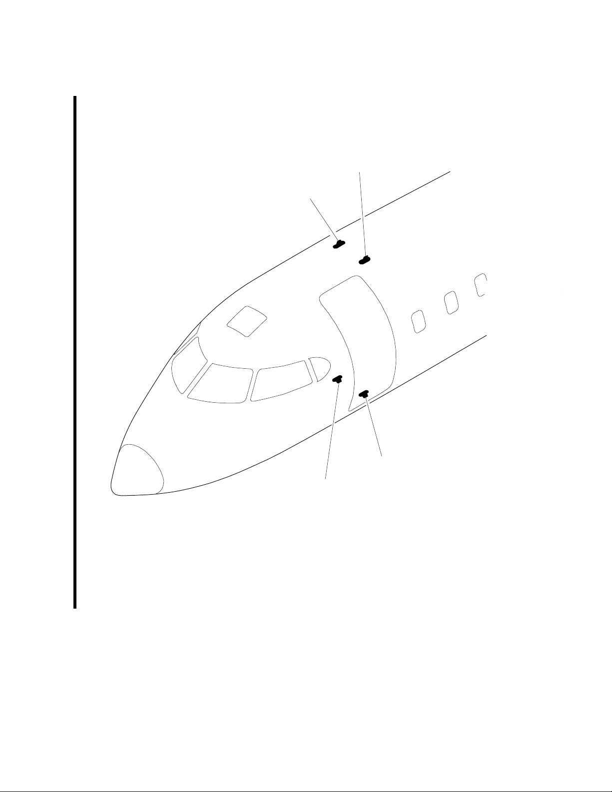
basd3a01.cgm
ATC 2
ATC 1
ATC 2
ATC 1
Antenna Locations −Adjustment/Test
Figure 503
Internal PSA Document
CRJ-900
AIRCRAFT MAINTENANCE MANUAL
PSA AIRLINES, INC REVISION
EFFECTIVITY: Ref page 1 of Blue Page
34-54-00-720-802-PSA Rev A
AMM - Insert after Task 34-54-00-720-802-A01 of AMM 34-54-00
Remove Rev 34-54-00-720-802PSA dated Sep 17/14 and insert 34-54-00-720-802-PSA Rev A dated 10/12/15
10/12/15
Page 13 of 13


