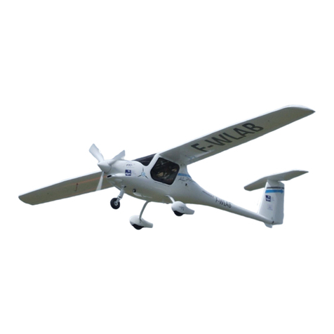
Pipistrel VELIS Electro Owner's manual

VELIS Electro
Document No.: POH-128-00-40-001
REVISION B00
Date of Issue: June 10th, 2020
Signature:
Registration: ____________________________
Serial No.: ____________________________
All rights reserved. Reproduction or disclosure to third parties of this document or any
part thereof is not permitted, except with the prior and express written permission of
Pipistrel Group’s R&D division, Pipistrel Vertical Solutions d.o.o., which is authorized to
publish technical documentation for Pipistrel Group’s subsidiaries.
PILOT'S OPERATING
HANDBOOK
Digitally signed by
Vid Plevnik
Reason: HOA
Location: Ajdovscina, Slovenia, EU
Date: 2020/06/10 15:21 +02'00'

ii
PAGE
VELIS Electro
Pilot's Operating Handbook
POH-128-00-40-001
PAGE REV. 0
Aircraft type: Virus SW 121
Model: Virus SW 128
T.C. no.: EASA.A.573
Type certificate holder: PIPISTREL VERTICAL SOLUTIONS d.o.o.
Vipavska cesta 2
SI-5270 Ajdovščina
Slovenia
Tel: + 386 5 36 63 873
Fax: + 386 5 36 61 263
Email: [email protected]
This handbook includes all of the material required to be provided to the
pilot by CS-LSA regulations. Additional information, deemed necessary by
the TC holder, is also included.
Those pages marked as “APPROVED” are approved by the European
Aviation Safety Agency.
The airplane must be operated in compliance with information and limita-
tions contained herein.
Pilot's Operating Handbook

iii
VELIS Electro
Pilot's Operating Handbook
POH-128-00-40-001
PAGE REV. 0
PAGE
SECTION CONTENTS
0FOREWORD
1GENERAL
2LIMITATIONS
3EMERGENCY PROCEDURES
4NORMAL PROCEDURES
5PERFORMANCE DATA
6WEIGHT AND BALANCE
7AIRPLANE DESCRIPTION
8HANDLING AND SERVICING
9APPENDIX
Table of contents

iv
PAGE
VELIS Electro
Pilot's Operating Handbook
POH-128-00-40-001
PAGE REV. 0
Special statements in the Pilot's Operating Handbook/Airplane Flight Man-
ual concerning the safety or operation of the airplane are highlighted by
being prefixed by one of the following terms:
WARNING: Means that the non-observance of the corresponding proce-
dures lead to an immediate or significant degradation in flight safety.
CAUTION: Means that the non-observance of the corresponding proce-
dures leads to a minor or to a long term degradation of the flight safety.
NOTE: Draws the attention to any special item not directly related to safety
but which is important or unusual.
Revision tracking, filing and identifying
Pages to be removed or replaced in this pilot's operating handbook (POH)
are determined by the log of effective pages located in this section. This log
contains the page number and revision number for each page within the
POH. As revisions to the POH occur, the revision number on the affected
pages is updated and the page number in the log is highlighted with bold
font type. When two pages display the same page number, the page with the
latest revision shall be used in the POH.
The revision number on the log of effective pages shall also coincide with
the revision number of the page in question. As an alternative to removing
and/or replacing individual pages, the owner can also print out a whole new
manual in its current form.
Revised material is marked with a vertical bar that will extend the full length
of deleted, new or revised text added to new or previously existing pages.
This marker will be located adjacent to the applicable text in the marking on
the outer side of the page. The same system applies when the header, figure
or any other element inside this POH is revised. A list of revisions is located
at the beginning of the log of effective pages. Pipistrel is not responsible for
technical changes/updates to OEM manuals supplied with the aircraft (e.g.
radio, transponder, GPS, etc.).
USING THIS HANDBOOK
v
VELIS Electro
Pilot's Operating Handbook
POH-128-00-40-001
PAGE REV. 0
PAGE
Doc.
Rev.
Reason for
revision Aected pages Authority
B00 Initial ALL
EASA
10.06.2020
Index of document revisions

vi
PAGE
VELIS Electro
Pilot's Operating Handbook
POH-128-00-40-001
PAGE REV. 0
PAGE
NUMBER
PAGE
REV.
PAGE
NUMBER
PAGE
REV.
PAGE
NUMBER
PAGE
REV.
PAGE
NUMBER
PAGE
REV.
2
2 - 1 0
2 - 2 0
2 - 3 0
2 - 4 0
2 - 5 0
2 - 6 0
2 - 7 0
2 - 8 0
2 - 9 0
2 - 10 0
2 - 11 0
2 - 12 0
2 - 13 0
2 - 14 0
2 - 15 0
2 - 16 blank
1
1 - 1 0
1 - 2 0
1 - 3 0
1 - 4 0
1 - 5 0
1 - 6 0
1 - 7 0
1 - 8 0
1 - 9 0
1 - 10 0
1 - 11 0
1 - 12 0
0
Cover -
ii 0
iii 0
iv 0
v0
vi 0
vii 0
viii 0
3
3
3 - 35 0
3 - 36 0
3 - 37 0
3 - 38 0
3 - 39 0
3 - 40 0
3 - 41 0
3 - 42 0
3 - 43 0
3 - 44 0
3 - 45 0
3 - 46 0
3 - 47 0
3 - 48 0
3 - 49 0
3 - 50 blank
3 - 51 0
3 - 52 0
3 - 53 0
3 - 54 0
3 - 55 0
3 - 56 0
3 - 57 0
3 - 58 0
3 - 59 0
3 - 60 0
3 - 61 0
3 - 62 0
3 - 63 0
3 - 64 0
3 - 65 0
3 - 66 0
3 - 67 0
3 - 68 0
List of eective pages
3
3 - 1 0
3 - 2 0
3 - 3 0
3 - 4 blank
3 - 5 0
3 - 6 0
3 - 7 0
3 - 8 0
3 - 9 0
3 - 10 0
3- 11 0
3 - 12 0
3 - 13 0
3 - 14 0
3 - 15 0
3 - 16 0
3 - 17 0
3 - 18 0
3 - 19 0
3 - 20 0
3 - 21 0
3 - 22 0
3 - 23 0
3 - 24 0
3 - 25 0
3 - 26 0
3 - 27 0
3 - 28 0
3 - 29 0
3 - 30 0
3 - 31 0
3 - 32 0
3 - 33 0
3 - 34 0

vii
VELIS Electro
Pilot's Operating Handbook
POH-128-00-40-001
PAGE REV. 0
PAGE
4
4 - 1 0
4 - 2 0
4 - 3 0
4 - 4 0
4 - 5 0
4 - 6 0
4 - 7 0
4 - 8 0
4 - 9 0
4 - 10 0
4 - 11 0
4 - 12 0
4 - 13 0
4 - 14 0
4 - 15 0
4 - 16 0
4 - 17 0
4 - 18 blank
4 - 19 0
4 - 20 blank
4 - 21 0
4 - 22 0
4 - 23 0
4 - 24 0
4 - 25 0
4 - 26 0
4 - 27 0
4 - 28 0
4 - 29 0
4 - 30 0
4 - 31 0
4 - 32 blank
PAGE
NUMBER
PAGE
REV.
PAGE
NUMBER
PAGE
REV.
PAGE
NUMBER
PAGE
REV.
PAGE
NUMBER
PAGE
REV.
5
5 - 1 0
5 - 2 0
5 - 3 0
5 - 4 0
5 - 5 0
5 - 6 0
5 - 7 0
5 - 8 0
5 - 9 0
5 - 10 0
5 - 11 0
5 - 12 0
5 - 13 0
5 - 14 0
5 - 15 0
5 - 16 0
5 - 17 0
5 - 18 0
5 - 19 0
5 - 20 0
5 - 21 0
5 - 22 0
5 - 23 0
5 - 24 0
5 - 25 0
5 - 26 0
6
6 - 1 0
6 - 2 0
6 - 3 0
6 - 4 0
6 - 5 0
6 - 6 blank
7
7 - 1 0
7 - 2 0
7 - 3 0
7 - 4 blank
7 - 5 0
7 -6 0
7 - 7 0
7 - 8 0
7 - 9 0
7 - 10 0
7 - 11 0
7 - 12 0
7 - 13 0
7 - 14 0
7 - 15 0
7 - 16 0
7 -17 0
7 - 18 0
7 - 19 0
7 - 20 0
7 - 21 0
7 - 22 0
7 - 23 0
7 - 24 0
7 - 25 0
7 - 26 0
7 - 27 0
7 - 28 0
7 - 29 0
7 - 30 0
7 - 31 0
7 - 32 0
7 - 33 0
3
3 - 69 0
3 - 70 0
3 - 71 0
3 -72 blank

viii
PAGE
VELIS Electro
Pilot's Operating Handbook
POH-128-00-40-001
PAGE REV. 0
PAGE
NUMBER
PAGE
REV.
PAGE
NUMBER
PAGE
REV.
PAGE
NUMBER
PAGE
REV.
PAGE
NUMBER
PAGE
REV.
9-A1
9-A1-1 0
9-A1-2 0
9-A1-3 0
9-A1-4 0
9-A1-5 0
9-A1-6 0
9-A1-7 0
9-A1-8 0
9-A1-9 0
9-A1-10 0
9-A1-11 0
9-A1-12 0
9-A1-13 0
9-A1-14 0
9-A1-15 0
9-A1-16 0
9-A1-17 blank
back-cover -
9-A0-1 0
9-A0-2 0
8
8 - 1 0
8 - 2 0
8 - 3 0
8 - 4 0
8 - 5 0
8 - 6 0
8 - 7 0
8 - 8 0
8 - 9 0
8 - 10 0
8 - 11 0
8 - 12 0
8 - 13 0
8 - 14 0
8 - 15 0
8 - 16 0
7 - 34 0
7 - 35 0
7 - 36 0

SECTION
1

1-2
PAGE
VELIS Electro
Pilot's Operating Handbook
POH-128-00-40-001
PAGE REV. 0
PART SUBJECT PAGE NUMBER
1.1 INTRODUCTION 1-3
1.2 DESCRIPTION 1-3
1.3 CERTIFICATION BASIS 1-3
1.4 THREE VIEW DRAWINGS 1-4
1.5 DIMENSIONS AND WEIGHTS 1-5
1.6
SYSTEMS 1-5
Engine
Propeller
Battery System
Landing Gear
1.7 SYMBOLS, ABBREVIATIONS and TERMINOLOGY 1-7
1.8 CONVERSION TABLE 1-11
1.9 LIST OF APPLICABLE DOCUMENTS 1-12
SECTION 1 – GENERAL
TABLE OF CONTENTS

1-3
VELIS Electro
Pilot's Operating Handbook
POH-128-00-40-001
PAGE REV. 0
PAGE
SECTION 1
GENERAL
1.1. INTRODUCTION
This section contains information of general interest to pilots and owners.
You will find the information useful in acquainting yourself with the airplane,
as well as in loading, sheltering, and handling the airplane during ground
operations. Additionally, this section contains definitions or explanations of
symbols, abbreviations, and terminology used throughout this handbook.
1.2. DESCRIPTION
The VELIS Electro is a two-seat aircraft of composite construction. The air-
craft is arranged as a high wing mono-plane with cantilevered wings and a
conventional empennage with a T-tail. It is equipped with a Pipistrel electric
engine E-811-268MVLC and a fixed pitch propeller Pipistrel P-812-164-F3A.
The seats are side-by-side with full dual flight controls and shared levers for
power output and flaperon control. Access to the cockpit is via two large
gull-wing doors. There is no baggage compartment on the aircraft.
The load-bearing structure of the airplane is made of carbon, glass and ara-
mid fiber composite material, the components of which, epoxy resin as well
as fiber materials, are in compliance with worldwide accepted aviation spec-
ifications. The proven, low-pressure wet lay-up method from the sailplane
industry is used to build the airplane structure.
The airplane is not approved for intentional spins and glider-towing.
1.3. CERTIFICATION BASIS
This aircraft is being certified under EASA CS-LSA Light Sport Aircraft Certi-
fication Specifications. Operation is restricted to VFR-day operations and a
maximum take oweight of 600 kg.

1-4
PAGE
VELIS Electro
Pilot's Operating Handbook
POH-128-00-40-001
PAGE REV. 0
SECTION 1
GENERAL
VELIS Electro
3-view drawing
1.4. THREE VIEW DRAWING

1-5
VELIS Electro
Pilot's Operating Handbook
POH-128-00-40-001
PAGE REV. 0
PAGE
SECTION 1
GENERAL
1.5. DIMENSIONS AND WEIGHTS
Basic Dimensions
Length 6.49 m
Span 10.71 m
Height 2.08 m
Wing
Area 9.51 m²
Span 10.71 m
Mean aerodynamic chord 0.898 m
Horizontal Tail Metric
Area 1.02 m²
Span 2.18 m
Vertical Tail
Reference area 0.86 m²
Height 1.11 m
Weights
Maximum take oweight 600 kg
Design empty weight 428 kg
Design useful load 172 kg
Maximum baggage weight No baggage
1.6. SYSTEMS
1.6.1. ENGINE
The aircraft's Pipistrel E-811-268MVLC engine consists of an electric motor,
the Pipistrel 268 MVLC VHML, and a dedicated H300C controller, which pro-
vides a maximum rated take opower of 65 kW.
The motor is a liquid cooled, axial flux synchronous permanent magnet elec-
tric motor.
The aircraft's power electronics system is a liquid-cooled, high-voltage pow-
er controller, which provides three phase alternating supply (AC) to the mo-
tor. Maximum continuous current is 300A.

1-6
PAGE
VELIS Electro
Pilot's Operating Handbook
POH-128-00-40-001
PAGE REV. 0
SECTION 1
GENERAL
1.6.2. PROPELLER
VELIS Electro is equipped with a 3-blade fixed pitch, Pipistrel-designed
P-812-164-F3A propeller. It has a diameter 1640 mm. Its blades are made
from carbon fiber composite material and stainless steel. The blade root and
propeller hub are machined aluminum parts.
1.6.3. BATTERY SYSTEM
Theairplanefeaturesahighvoltageelectricpowersystem.Theprimaryenergy
source are two Pipistrel PB345V124E-L battery packs, which are located fore
and aft of the cabin. This ensures redundancy of the power-source. In case
of battery failure, the faulty battery gets automatically disconnected from the
system. A single battery is capable of standalone operation and has enough
power output capability to support aircraft climb and continuation of flight.
The batteries are controlled by a BMS, that continuously monitors and man-
ages battery parameters and status to ensure safe operations.
1.6.4. LANDING GEAR
The airplane has as a tricycle type fixed landing gear. The nose wheel is
steerable via rudder pedals. The main wheels are equipped with hydraulic
disc brakes, which are independently operated via toe-pedals. A parking
brake lever is also present.
Propulsion system
terminology

1-7
VELIS Electro
Pilot's Operating Handbook
POH-128-00-40-001
PAGE REV. 0
PAGE
SECTION 1
GENERAL
1.7. SYMBOLS, ABBREVIATIONS
AND TERMINOLOGY
1.7.1. GENERAL AIRSPEED TERMINOLOGY AND SYMBOLS
KCAS Knots Calibrated Airspeed is the indicated airspeed corrected for posi-
tion and instrument error expressed in knots. Calibrated airspeed (CAS) is
equal to true airspeed in standard atmosphere at sea level.
KIAS Knots Indicated Airspeed is the speed shown on the airspeed indicator
(IAS) expressed in knots. The IAS values published in this handbook as-
sume no instrument error.
KTAS Knots True Airspeed is the airspeed expressed in knots relative to undis-
turbed air which is KCAS corrected for altitude and temperature.
VGBest Glide Speed is the speed at which the greatest flight distance is at-
tained per unit of altitude lost with power o.
VAOperating Maneuvering Speed is the maximum speed at which applica-
tion of full control movement will not overstress the airplane.
VFE Maximum Flap Extended Speed is the highest speed permissible with
wing flaps in a prescribed extended position.
VNO Maximum Structural Cruising Speed is the speed that should not be ex-
ceeded except in smooth air, and then only with caution.
VNE Never Exceed Speed is the speed that may not be exceeded at any time.
VS0 Stalling Speed is the minimum steady flight speed at which the aircraft is
controllable in the landing configuration (100% flaps) at the most unfavor-
able weight and balance.
VXBest Angle of Climb Speed is the speed at which the airplane will obtain
the highest altitude in a given horizontal distance. The best angle-of-climb
speed normally increases slightly with altitude.
VYBest Rate of Climb Speed is the speed at which the airplane will obtain
the maximum increase in altitude per unit of time. The best rate-of-climb
speed decreases slightly with altitude.
VHMaximum speed in level flight with maximum continuous power.
GS Ground Speed is the horizontal speed relative to the ground.

1-8
PAGE
VELIS Electro
Pilot's Operating Handbook
POH-128-00-40-001
PAGE REV. 0
SECTION 1
GENERAL
1.7.2. METEOROLOGICAL TERMINOLOGY
IMC Instrument Meteorological Conditions are meteorological conditions ex-
pressed in terms of visibility, distance from cloud, and ceiling less than
the minimal for visual flight defined in FAR 91.155.
ISA International Standard Atmosphere (standard day) is an atmosphere
where
(1) the air is a dry perfect gas,
(2) the temperature at sea level is 15 °C,
(3) the pressure at sea level is 1013.2 millibars (29.92 inHg), and
(4) the temperature gradient from sea level to the altitude at which the
temperature is -56.5 °C is -0.00198 °C per foot and zero above that
altitude.
MSL Mean Sea Level is the average height of the surface of the sea for all
stages of tide. In this Handbook, altitude given as MSL is the altitude
above the mean sea level. It is the altitude read from the altimeter when
the altimeter’s barometric adjustment has been set to the altimeter set-
ting obtained from ground meteorological sources.
OAT Outside Air Temperature is the free air static temperature obtained from
in-flight temperature indications or from ground meteorological sources.
It is expressed in either degrees Celsius or degrees Fahrenheit.
PA Pressure Altitude is the altitude read from the altimeter when the al-
timeter’s barometric adjustment has been set to 1013 mb (29.92 inHg)
corrected for position and instrument error. In this Handbook, altimeter
instrument errors are assumed to be zero.
DA Density Altitude (ft) is pressure altitude corrected for non-standard tem-
perature. As temperature and altitude increase, air density decreases.
- Standard Temperature is the temperature that would be found at a given
pressure altitude in the standard atmosphere. It is 15 °C at sea level pres-
sure altitude and decreases approx. 2 °C for each 1000 feet of altitude
increase.
AAL Above Aerodrome Level

1-9
VELIS Electro
Pilot's Operating Handbook
POH-128-00-40-001
PAGE REV. 0
PAGE
SECTION 1
GENERAL
1.7.3. PROPULSION SYSTEM TERMINOLOGY
BMS Battery Management System
ENGINE In this POH is defined as the system composed by electric motor
and power controller.
HP Horsepower is the power developed by the motor.
INTERLOCK A system that detects power cable connection to the battery
box. In case of disconnection, also interlock signal is lost and
disconnection is detected.
kW Kilowatt: it is unit that express the power developed by the motor.
MCP Maximum Continuous Power is the maximum power that can be
used continuously.
MPTOP Minimum Performance Take oPower is the maximum power
available for take owith batteries at the end of their service life
and low SOC (SOH~0% and SOC=15%).
MTOP Maximum Take OPower is the maximum power available for
take o, albeit for a limited time. This value can be reached
when batteries are in good condition (high SOC/SOH).
PROPULSION
SYSTEM
In this POH is defined as the system composed by electric mo-
tor, power controller, propeller and batteries.
RFT Remaining Flight Time (displayed on EPSI, for information only)
RPM Revolutions Per Minute is motor rotational speed.
SOC State Of Charge (displayed on EPSI - Flight page) is the amount
of energy stored in the battery, expressed as percentage of full
capacity. Absolute full capacity is not constant, but can be af-
fected by several factors (i.e. SOH, temperature).
SOH State Of Health (displayed on EPSI - System page) indicates the
"age" of the battery. End of life is SOH=0%. This parameter af-
fects the absolute capacity of the battery (energy that can be
stored), and the power that the battery can deliver.
TC Power module of the charger.
1.7.4. PERFORMANCE TERMINOLOGY
gOne “g” is a quantity of acceleration equal to that of earth’s gravity.
-Demonstrated Crosswind Velocity is the velocity of the crosswind com-
ponent for which adequate control of the airplane during taxi, take o,
and landing was actually demonstrated during certification testing.
- Service Ceiling is the maximum altitude at which the aircraft at maximum
weight has the capability of climbing at a 100 ft/min.

1-10
PAGE
VELIS Electro
Pilot's Operating Handbook
POH-128-00-40-001
PAGE REV. 0
SECTION 1
GENERAL
1.7.5. WEIGHT AND BALANCE TERMINOLOGY
MTOM Maximum Take OMass is the maximum overall mass allowed at take
o.
C.G. or
CG
Center of Gravity is the point at which an airplane would balance if sus-
pended. Its distance from the reference datum is found by dividing the
total moment by the total weight of the airplane. All references to C.G. in
this manual are references to the in-flight C.G.
- Arm is the horizontal distance from the reference datum to the center of
an item’s gravity. The airplane’s arm is obtained by adding the airplane’s
individual moments and dividing the sum by the total weight.
- Basic Empty Weight is the actual weight of the airplane including all op-
erating fix installed equipment of the airplane.
MAC Mean Aerodynamic Chord is the chord drawn through the centroid of
the wing plan area.
R or
LEMAC
Leading Edge of Mean Aerodynamic Chord is the forward edge of MAC
aft of the reference datum.
- Maximum Gross Weight is the maximum permissible weight of the air-
plane and its contents as listed in the aircraft specifications.
- Moment is the product of the item weight multiplied by its arm.
- Useful Load is the basic empty weight subtracted from the maximum
weight of the aircraft. It is the maximum allowable combined weight of
pilot and passenger.
- Reference Datum is an imaginary vertical plane from which all horizontal
distances are measured for balance purposes.
- Tare is the weight of all items used to hold the airplane on the scales for
weighing. Tare includes blocks, shims, and chocks. Tare weight must be
subtracted from the associated scale reading.
WBR Weight and Balance Report is part of the aircraft documentation and is a
record of aircraft empty weight and C.G. location.
MLE Minimum List of Equipment is the list of instruments, systems and equip-
ment that must be on board and functional for a kind of operation.
TOM Take OMass is the aircraft mass at take o. On VELIS Electro this value
does not change during the entire flight.

1-11
VELIS Electro
Pilot's Operating Handbook
POH-128-00-40-001
PAGE REV. 0
PAGE
SECTION 1
GENERAL
1.7.6. ADDITIONAL ABBREVIATIONS
AH Artificial Horizon
AHRS Attitude and Heading Reference System
AOA Angle Of Attack
BATT Battery/Batteries
COM Communication - Radio
EA Electrical Aircraft
ELT Emergency Locator Transmitter
HV High Voltage
IFR Instrumental Flight Rules
NVFR Night-Visual Flight Rules
PVS Pipistrel Vertical Solutions
VFR Visual Flight Rules
1.8 CONVERSION TABLE
SI US US SI
1 bar 14.5037 psi 1 psi 0.0689 bar
1 mm2 0.0016 in2 1 in2 625 mm2
1 cm2 0.1550 in2 1 in2 6.4510 cm2
1 daN 2.2481 lbf 1 lbf 0.4448 daN
1 g 0.0353 oz 1 oz 28.328 g
1 hPa 0.0295 inHg 1 inHg 33.898 hPa
1 kg 2.2046 lb 1 lb 0.4536 kg/min
1 kg/min 2.2046 lb/min 1 lb.min 0.4536 kg/min
1 l 0.2641 US gal 1 US gal 3.7864 l/min
1 l 1.057 US quart 1 US quart 0.9461 l
1 l/min 0.2641 US gal/min 1 US gal.min 3.7864 l/min
1 daNm 88.4956 lbf.in 1 lbf.in 0.0113 daNm
1 daNm 7.3801 lbf.ft 1 lbf.ft 0.1355 daNm
1 m 3.2809 ft 1 ft 0.3040 m
1 mm 0.0394 in 1 in 16.393 mm
1 cm3 0.06102 in3 1 in3 16.393 cm3
1 hPa 0.0145 psi 1 psi 68.965 hPa

1-12
PAGE
VELIS Electro
Pilot's Operating Handbook
POH-128-00-40-001
PAGE REV. 0
SECTION 1
GENERAL
1.9 LIST OF APPLICABLE DOCUMENTS
Reference Document
[1] WBR-128-08-10-XXX* Weight and Balance Report
[2] ELT_345_Manual_Y1-03-0282J
[3] EIM-811-00-60-7202 Engine Operator`s Manual
[4] PIM-812-61-00-001 Propeller Instruction Manual
[5] AMM-128-00-60-001 Aircraft maintenance manual
[6] Horis - Installation and User Manual (by Kanardia d.o.o.)
[7] SB-128-00-80-001 Flight_Data_Logging
[8] SPOH-128-00-40-001 Leaflet ground risks
* Where XXX represents the aircraft's serial number
NOTE: Latest revision of listed documents has to be used.
This manual suits for next models
2
Table of contents
Other Pipistrel Aircraft manuals

Pipistrel
Pipistrel Sinus 503 Installation and operating manual

Pipistrel
Pipistrel ALPHA Trainer User manual

Pipistrel
Pipistrel Sinus User manual

Pipistrel
Pipistrel Virus SW 121 Owner's manual

Pipistrel
Pipistrel Alpha Electro Owner's manual

Pipistrel
Pipistrel Sinus 503 User manual

Pipistrel
Pipistrel Virus 912 S-LSA Glider User manual

Pipistrel
Pipistrel LSA-MRA User manual

Pipistrel
Pipistrel ALPHA Trainer LSA Owner's manual

Pipistrel
Pipistrel FP03-60E User manual