AeroVironment TurboCord User manual
USER GUIDE
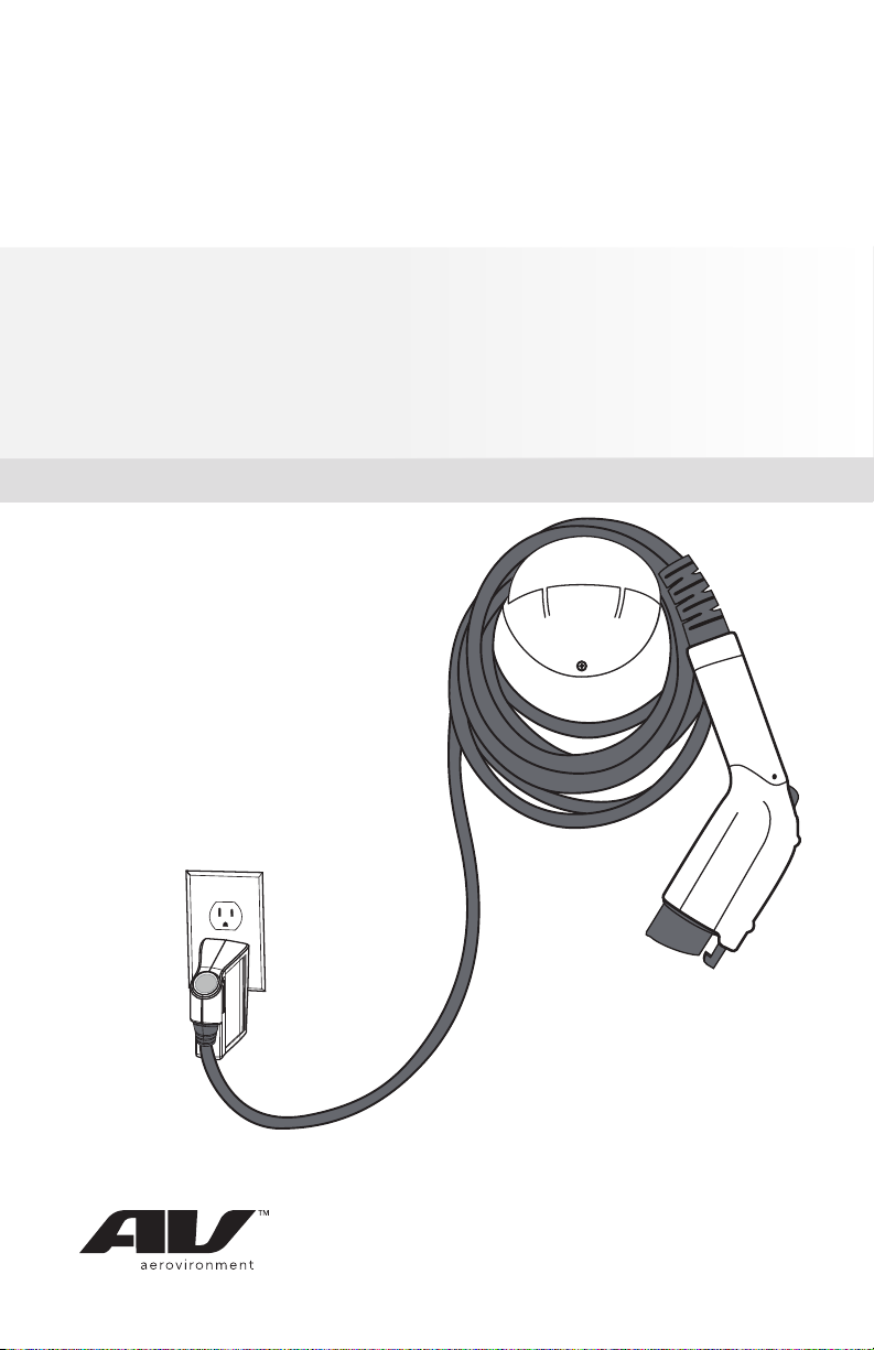
TURBOCORDTM PORTABLE CHARGER
120V/240V: DUAL VOLTAGE
AeroVironment EV Solutions™

© 2013 AeroVironment, Inc. All rights reserved.
AeroVironment, EV Solutions, and the AeroVironment logo are trademarks of AeroVironment, Inc.
Corporate names, trademarks, registered trademarks, service marks, symbols, and logos stated herein are property of their
respective companies.
Specifications are subject to change without notice. Images of the Dual voltage charger are representative; production mod-
els may vary. Dual voltage charger may be branded under different names.
No portion of these materials may be duplicated, used or disclosed without prior written permission from AeroVironment, Inc.
Disclaimer: This user guide includes the latest information available at the time of printing. AeroVironment, Inc. reserves the
right to make changes to this user guide and/or product without further notice. Changes or modifications to this product not
completed by an authorized service provider could void the product warranty.
Corporate Headquarters
AeroVironment, Inc.
EV Solutions™
181 W. Huntington Drive, Suite 202
Monrovia, CA 91016
Phone: 626-357-9983 or 888-833-2148
Fax: 626-359-9628
Email: ev@avinc.com
Website: www.evsolutions.com

i
A NOTE ON CUSTOMER SUPPORT
To ensure superior service, please take note of your Serial Number when
contacting AeroVironment Customer Support.
Write down the Serial Number of your charger in the “Owner’s Record” above.
The Serial Number can be found on the bottom of the charger’s plug-in
module.
AeroVironment EV Solutions
Customer Support
1-888-833-2148
evscs@avinc.com
OWNER’S RECORD
model:
TurboCord Dual Voltage Charger
serial number (s/n):
purchase date:
P22603-03,1

ii
SAVE THESE INSTRUCTIONS!
This manual contains important instructions for the TurboCord Dual Voltage
Charger that shall be followed during installation, operation and maintenance
of the unit.
TABLE OF CONTENTS
SECTION 1: INTRODUCTION...................................................1
Symbol Usage.................................................................................2
About Your TurboCord Charger...................................................3
TurboCord Charger Components................................................5
Required Outlets............................................................................6
SECTION 2: USING YOUR DUAL VOLTAGE CHARGER....7
Know Your Indicator Lights ...........................................................8
Charging Your Vehicle ...................................................................9
120 VAC Mode........................................................................9
240 VAC Mode......................................................................10
Manual Stop.................................................................................. 11
A Note on Auto-Restart ..............................................................11
SECTION 3: TROUBLESHOOTING...................................... 12
APPENDIX ................................................................................ 15
Specifications ...............................................................................16
Installing the Cable Hanger........................................................17
High Voltage Warning .................................................................18
State of California Proposition 65 Warnings .............................19
FCC Information...........................................................................19
Safety Features.............................................................................19
Warranty........................................................................................21
Index..............................................................................................22

SECTION 1
INTRODUCTION

2
SYMBOL USAGE
Indicates information about safety practices which, if not
followed, may result in serious injury or death.
.............................................................................................
Indicates information about safety practices which, if not
followed, could result in personal injury or are necessary
to prevent fire or equipment overheating.
.............................................................................................
Indicates helpful information for installation or usage, but
does not contain personnel or equipment safety related
information.
DANGER
NOTE
WARNING
3
WARNING
WARNING
WARNING
ABOUT YOUR TURBOCORD CHARGER
Thank you for purchasing the AeroVironment™ (AV) TurboCord Dual Voltage
Charger – our easy-to-use, compact, and portable power supply for your electric
vehicle’s on-board charger. The charger supplies and manages AC power to your
electric vehicle and is compatible with a variety of battery electric and plug-in
hybrid electric vehicles.
The charger will operate from either a 120 VAC or a 208/240 VAC 60 hertz power
source. The included adapter is required for 208/240 VAC operation.
KEY FEATURES
• Dual voltage capability
• Compact, portable design
• Overheating protection
• Quick-read status indicators
• Underwriters Laboratories (UL) listed
• SAE J1772 compliant
• Auto-restart in event of ground fault or power outage
The adapter is designed for use with the charger in 208/240
VAC operating mode only. DO NOT connect other devices
to the adapter. NEVER use the charger with any AC adapter
except for the adapter supplied by the manufacturer
specifically for use with this charger.
120 VAC Operation: the charger requires a 120 VAC single phase dedicated
circuit. It draws a maximum of 12-amp continuous current and requires a 15-amp
rated circuit breaker.
240 VAC Operation: the charger requires either a 240 VAC split phase, or a
208 VAC two phase dedicated circuit. It draws a maximum of 16-amp continuous
current and requires a 20-amp rated circuit breaker.
It is recommended that electrical outlets for use with your
charger be installed by a licensed, qualified electrician . To
avoid serious injury or death, installation must comply with
the provisions of the National Electric Code (NEC) and all
local codes. In cases of conflict between local codes and the
NEC, local codes shall take precedence.
This product must be grounded. If it should malfunction or
break down, grounding provides a path of least resistance
for electric current to reduce the risk of electric shock.
This product is equipped with a cord having an equipment
grounding conductor and a grounding plug. The plug
must be inserted into an appropriate outlet that is properly
installed and grounded in accordance with all local codes
and ordinances.

4
DANGER
WARNING
WARNING
NOTE
WARNING
Improper connection of the electrical outlet grounding
conductor might result in a risk of electric shock. Check
with a qualified electrician if you are uncertain whether
or not the electrical outlet is properly grounded. Do not
modify the plug provided with the product if it does
not fit in the outlet. Have a proper outlet installed by a
qualified electrician.
.............................................................................................
Do NOT DROP charger or coupler.
.............................................................................................
If the output cable becomes separated from the charger
module or the charge coupler, DO NOT ATTEMPT TO
REPAIR THE CABLE YOURSELF. Contact AV Customer
Support for assistance.
.............................................................................................
When using your charger, basic precautions should always
be followed, including the following:
• See warnings on charger cord label. Read warnings
before operating the unit the first time. Read all
instructions in this guide before using this product.
• Never use the charger with an extension cord.
• Shock hazard – make sure the plug is fully inserted
into the wall outlet so that there are no exposed blade
surfaces.
• Children should be supervised when in the vicinity of
the charger while plugged in.
• Do not put fingers into the electric charge coupler.
• To reduce the risk of fire, connect only to a circuit
provided with 20 amps maximum branch circuit
overcurrent protection.
• Do not use in a commercial garage classified for
internal combustion engine vehicles due to vapors of
flammable liquids (gasoline) being present.
TurboCord will not charge and will give a fault indication if
ground is not present.

5
TURBOCORD CHARGER COMPONENTS
Release button
240 V ADAPTER
240 V ADAPTER CLIP
CHARGE MODULE
CHARGE COUPLER
6
NOTE
NOTE
NOTE
REQUIRED OUTLETS
Any electrical socket should be checked by an electrician.
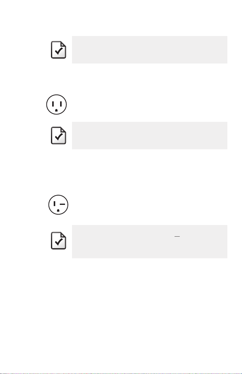
120 VAC operation: a NEMA 5-15R wall outlet is required.
NEMA 5-15R receptacle
120 V
A dedicated 120 VAC single phase circuit and a 15-amp
rated circuit breaker are required.
208/240 VAC operation: a NEMA 6-20R wall outlet is required.
NEMA 6-20R wall receptacle
240 V
A dedicated 240 VAC split phase circuit or a 208 VAC
two phase circuit and a 20-amp rated circuit breaker are
required.

SECTION 2
USING YOUR
TURBOCORD CHARGER
8
NOTE
WARNING
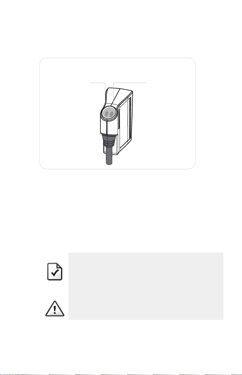
KNOW YOUR INDICATOR LIGHTS
The indicator light on your dual voltage charger is the first thing you will notice
when you are about to plug or unplug your vehicle. Before we get started, here
is a simple explanation of the indicators.
BLUE: STATUS
When plugged into the wall outlet, the BLUE STATUS Indicator illuminates to
communicate that the charger is ready to use.
RED: TROUBLE
The RED TROUBLE Indicator illuminates when the charger has detected an
error. If the RED TROUBLE Indicator is illuminated, the charger will not deliver
power to the vehicle. The error must be corrected before a charging cycle can
begin or continue. Refer to the Troubleshooting Guide in Section 3 for more
information.
A momentary blink of the RED TROUBLE Indicator at first
plug-in to the wall socket is normal and functions as a
startup safety check. This momentary blink is followed by
the solid BLUE STATUS Indicator and the RED TROUBLE
Indicator turns off.
.............................................................................................
A constant or blinking RED TROUBLE Indicator indicates
an actual problem.
Blue STATUS
Indicator light
Red TROUBLE
Indicator light
CHARGE MODULE INDICATOR LIGHTS

9
CHARGING YOUR VEHICLE
Your charger is designed for easy charging in two modes – 120 VAC and 240
VAC.
120 VAC MODE
When used WITHOUT the ADAPTER, the charger connects to a 120 V outlet
and charges your vehicle in “Level 1” charging mode. The Level 1, 120 VAC
charge regimen takes longer to charge than the Level 2, 240 VAC mode;
however 120 VAC wall outlets are typically more readily available.
1. Insert the CHARGE MODULE into the appropriate 120V wall outlet.
2. The BLUE STATUS Indicator on the CHARGE MODULE should be ON. This
means that the charger is ready to provide power to your vehicle.
3. Plug the CHARGE COUPLER into your vehicle’s charging outlet until it
clicks. If inserted properly, the BLUE STATUS Indicator will blink once. Once
latched, the CHARGE COUPLER will not disengage unless the release
button is pressed manually.
4. Automatic charge begins. Power will be delivered in accordance to
vehicle demand. If the vehicle is charging, the BLUE STATUS Indicator will
blink on and off approximately every two seconds. Always verify that the
vehicle charging status indicator agrees.
5. When fully charged, the BLUE STATUS Indicator light illuminates solid
blue. Your vehicle has a “dashboard gauge” which can verify that the
vehicle is fully charged. Refer to the vehicle owner’s manual to find the
gauge location on your dashboard.
6. Disconnect when the charge is complete by pressing the release button
on the CHARGE COUPLER and removing it from the vehicle.
10
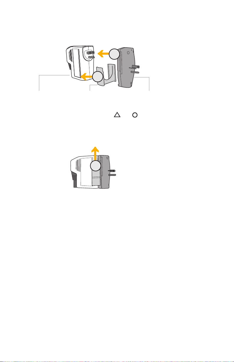
240 VAC MODE
When used WITH the ADAPTER, the charger can charge in Level 2, 240 VAC
mode.
1. Snap the ADAPTER CLIP to the lower end of the CHARGE MODULE,
lining up the appropriate symbols ( and ) on the clip and module.
2. Insert the CHARGE MODULE into the ADAPTER (make sure it is fully
inserted or the clip will not slide into the lock position).
3. Slide the ADAPTER CLIP up to the top of the CHARGE MODULE to lock
in place.
4. Insert the CHARGE MODULE with the attached ADAPTER into the
appropriate 240 VAC wall outlet.
5. The BLUE STATUS Indicator on the CHARGE MODULE should be ON. This
means that the charger is ready to provide power to your vehicle.
6. Plug the CHARGE COUPLER into your vehicle’s charging receptacle until it
clicks. Once latched, the CHARGE COUPLER will not disengage unless the
release button is pressed manually.
7. Automatic charge begins. Power will be delivered in accordance to
vehicle demand. If the vehicle is charging, the BLUE STATUS Indicator will
blink on and off approximately every two seconds. Always verify that the
vehicle charging status indicator agrees.
8. When fully charged, the BLUE STATUS Indicator light illuminates solid
blue. Your vehicle has a “dashboard gauge” which can verify that the
vehicle is fully charged. Refer to the vehicle owner’s manual to find the
gauge location on your dashboard.
9. Disconnect when the charge is complete by pressing the release button
on the CHARGE COUPLER and removing it from the vehicle.
←
←
←
1
3
2
Charge Module Adapter Clip Adapter

11
NOTE
When plugging into an unfamiliar wall outlet, it is good
practice to let the vehicle charge for several minutes
before leaving it unattended, to ensure it is in fact
supplying the expected AC charging power.
The RED TROUBLE Indicator will illuminate if not charging.
The unit will turn OFF if breaker or infrastructure GFI is
tripped.
MANUAL STOP
To safely stop charging at any time before charge completion, just press the
CHARGE COUPLER release button and remove it from the vehicle.
Charging will automatically and safely stop.
BLUE STATUS Indicator remains ON solid.
A NOTE ON AUTO-RESTART
The Auto-Restart feature helps ensure that your vehicle will be charged and
ready for use when needed. A charge may be interrupted if an error is detected.
Charging will resume once the error is no longer detected. The RED TROUBLE
Indicator illuminates during an error condition.
The exception to immediate Auto-Restart is when the interruption is due to a
charger GFCI event. The charger will attempt to restart 15 minutes after a GFCI
event. After the fourth attempt to restart, the charger will shut down and the
RED TROUBLE Indicator will stay ON.
If the fault persists, do not continue to try to charge your vehicle. Contact AV
Customer Support.

CHAPTER 3
TROUBLE SHOOTING

13
NOTE
TROUBLESHOOTING
Please refer to this Troubleshooting Guide for possible solutions to common
errors or difficulties with charging your vehicle using your portable charger.
Do not attempt to repair or service the charger yourself.
There are no user serviceable parts inside.
A RED TROUBLE Indicator may be triggered by several sources, including the
charger, the utility service, or the vehicle. See Troubleshooting tips below.
The RED TROUBLE Indicator turns on when the charger detects an error
whether it is connected to your vehicle or not. With the RED TROUBLE Indicator
on, the dual charger will not deliver power to the vehicle. The error must be
corrected before charging begins or resumes.
Problem Possible Cause Solution
BLUE STATUS
Indicator does not
illuminate
No power to unit 1. Check circuit breaker and
other circuit loads.
2. Try another wall outlet.
3. Ensure charger module (and
adapter if operating in 240
VAC mode) is fully inserted
into the wall outlet.
Charger internal
failure
Contact AV Customer Support
for assistance.
Vehicle will not
charge
RED TROUBLE
Indicator remains
solid
Charge coupler is
not inserted into
the vehicle
1. Inspect the charge coupler.
2. Remove the charge coupler
from the vehicle, then reinsert
it into the vehicle receptacle
until it clicks.
Vehicle is not in a
state to accept a
charge
Verify vehicle charge timer is
set to permit charging. Refer to
the vehicle owner’s manual for
charge timer instructions.
Communication
error between
charger and
vehicle
Contact AV Customer Support
for assistance.

14
Problem Possible Cause Solution
RED TROUBLE
Indicator is blinking
rapidly
Utility fault 1. Disconnect the charger
module from the wall outlet,
then reconnect to the wall
outlet.
2. If the condition persists, have
a qualified electrician inspect
the wall outlet ground circuit
integrity.
3. Repair as required.
Above
temperature limit
Cases:
1. Temperature is
too high. The
charger will
restart charging
when it cools
down.
2. House/socket
wiring may be
faulty.
1. Inspect charger module for
overheating (hot to the touch).
a. Carefully unplug charger
module from the wall outlet
and allow to cool.
b. If the condition persists,
contact AV Customer
Support for assistance.
2. Disconnect the charger (and
adapter, if operating in 240
VAC mode) from the wall
outlet.
3. Have a qualified electrician
inspect the wall outlet and
adapter integrity.
a. Repair as required.
RED TROUBLE
Indicator is on solid
when connected to
vehicle
RED TROUBLE
Indicator is off
and BLUE STATUS
Indicator is on when
you unplug from
vehicle
Vehicle problem Contact your vehicle service
department.
RED TROUBLE
Indicator is on solid
NOT connected to
vehicle
Charger internal
failure
Contact AV Customer Support
for assistance.
RED TROUBLE
Indicator and BLUE
STATUS Indicator are
both on
Charger trying to
resolve internal
error
Charger will return to normal
operation within 1 minute. If
problem persists, contact AV
Customer Support for assistance.

APPENDIX

16
SPECIFICATIONS
Model Dual voltage
Line input power: 120 VAC
240/208 VAC
Output power: 12 amps continuous @ 120 VAC
16 amps continuous @ 240/208 VAC
Circuit breaker rating: 15 amps @ 120 VAC
20 amps @ 240 VAC
Frequency: 60 Hz
Power draw at idle
during charging:
< 2 watts
< 4 watts
Cable length: approximately 20 ft. (6.1 m)
Weight: 4 lb. (1.81 kg) – module
0.2 lb. (0.09kg) – adapter
Temperature –
operating: -40° C to +50° C (-40° F to 122° F)
Temperature –
storing and transporting: -40° C to +70° C (-40° F to +158° F)
Environmental rating: NEMA 6P (watertight)
Vehicle – Dual voltage charger
communication protocol: SAE J1772 compliant
Charge coupler: SAE J1772 compliant
Direction of charge: Grid to vehicle
Specifications are subject to change without notice.
Table of contents
Other AeroVironment Batteries Charger manuals


