Mennekes Basic User manual

ENGLISH
Installation manual
Foundation
Charging columns

2
Copyright © 2018 MENNEKES Elektrotechnik
GmbH & Co. KG
All rights are reserved by the publisher, including the
reprinting and the duplication of this manual and its
translation, in whole or in part. No part of this manual may
be reproduced in any form whatsoever, or copied with the
aid of an electronic duplication system, without the written
permission of the publisher. Observe protection notice in
accordance with DIN ISO 16016. The German version of
this manual is the original manual. Manuals in other langu-
ages are translations of this original manual.
1.1 Warning of personal injury
1.2 Warning of material damage
TDANGER
This warning notice indicates imminent danger that will
result in death or extremely severe injuries.
TWARNING
This warning notice indicates a dangerous situation that
can result in death or extremely severe injuries.
TCAUTION
This warning notice indicates a dangerous situation that
can result in material damage.
1. About this document 2. General information
The information in this manual only applies to the Basic,
Premium and Smart charging columns.
Depending on the version of the device, visual deviations
from the presentations in this manual can occur. Apart
from this manual, additional documentation may be inclu-
ded that you have to observe fully.
3. For your safety
3.1 General safety information
For your own safety, please read the general safety infor-
mation through carefully and observe it for safe operation.
In addition to this manual, please also observe the national
legal provisions (e. g. accident prevention and environ-
mental regulations) for the respective end-user country.
3.1.1 Workplace safety
fKeep your workplace clean and tidy.
fAvoid tripping hazards (associated with electric cables
lying around, for example).
fCordon off the working area, if necessary.
fDo not place unsecured device on footpaths or traffic
routes.
3.1.2 Electrical safety
fAvoid kinks and pinches.
fDo not route lines over sharp edges or objects.
fPrevent components (e.g. supply line) knocking over the
device.
fDo not place the device into water (e.g. puddle of
water).

3
ENEN
4.1.2 Minimum distances
db
ac
Minimum
distance [mm]
Charging column
Basic, Premium,
Smart (S / N / SN) Smart T / ST
a 250 1250
b 800 800
c 1250 1250
d 800 800
TCAUTION
Risk of property damage as a result of overheating!
If the charging column overheats, this may result in
malfunctions. Components may be damaged.
fObserve the minimum distances to avoid the charging
column overheating and enable unhindered access.
4.1 Installation
4.1.1 Requirements at the place of operation
Do not install in potentially explosive atmospheres (e.g.
gas refuelling stations).
Do not install in flood-prone areas.
Compliance with the local technical connection require-
ments and safety rules.
Maximum humidity (non-condensing): 95 %.
Ambient temperature between -25°C and +40°C,
mean temperature over 24-hour period < 35 °C.
The charging column must be protected from direct
exposure to water jets.
There must be sufficient space to observe minimum
distances.
fCheck whether the location chosen for operation is
suitable for the charging column. Ensure there is a
GPRS - radio connection at the installation site.
We recommend to use curb stones or bollards to
protect the charging column.
We recommend to use a pedestal filler to pro-
tect the charging column against humidity and
insects.
fFIll the charging column with a pedestal filler
(e. g. expanded clay Ø 4 - 8 mm) up to the
cleaning flap of the ventilation shaft
(filling height approx. 7 cm).
TWARNING
Risk of loss of life if installed incorrectly!
Failure to comply with the specifications for the ambient
conditions can lead to hazardous situations when wor-
king with electricity.
fEnsure that the requirements at the place of operation
are adhered to at all times.
4. Installation and commissioning

4
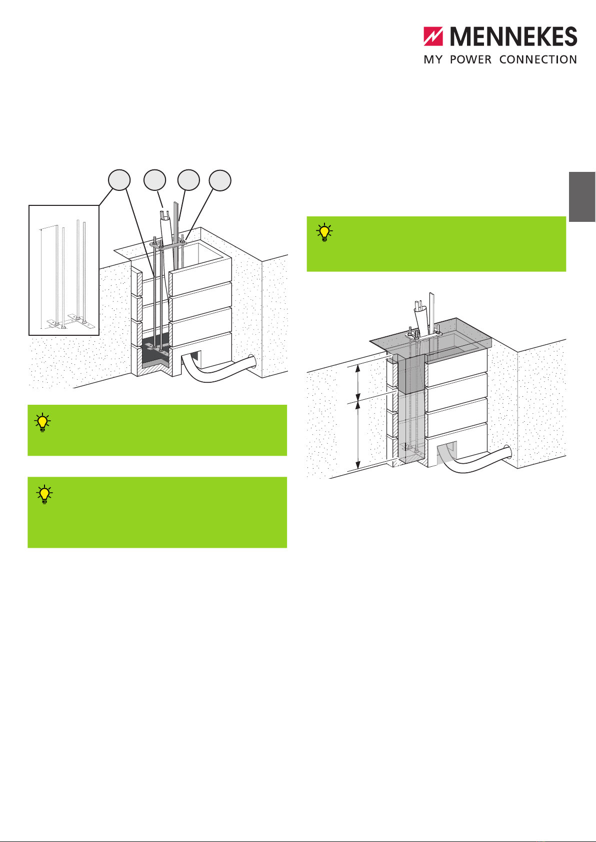
fPrepare earth excavation with the specified dimensions.
fUse right-angled shaft elements (2) to set a lost
formwork.
fPay attention to the opening (3) in the formwork for
inserting a hollow pipe Ø 70 mm (4).
fFeed the supply cable (1) and, if applicable, the BUS
cable (1) through the hollow pipe.
fClose the opening (3) around the hollow pipe using
construction foam or earth to prevent the foundation
concrete from leaking out.
4.2 Assembly
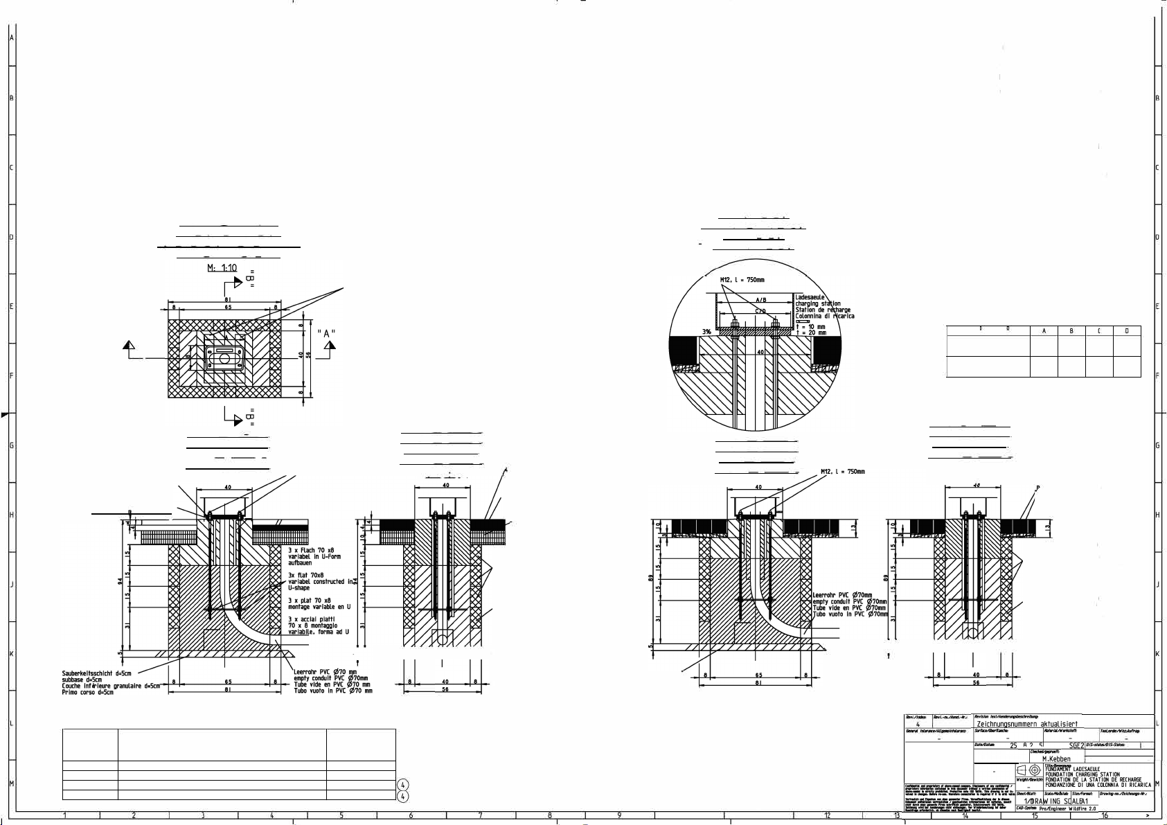
4.2.1 Preparing new foundation
ÎAlso observe the included technical drawings.
Dimensions
[mm]
Charging column
Basic, Premium,
Smart (S / N / SN) Smart T / ST
a 900 1000
b 900 900
c 600 900
TDANGER
Risk of death from electrocution!
Coming into contact with parts that conduct electricity
can result in electric shock, burns or death.
fDisconnect the unit from the power supply.
fEnsure that the power supply remains switched off
while performing the work.
b
c
a
1
2
3
4
5
ENEN
Installing the foundation set
To achieve optimum strength, we recommend
the MENNEKES foundation set available as an
accessory.
To achieve a secure and simple attachment
of the charging column, we recommend the
MENNEKES floor panel available as an accesso-
ry.
fIf necessary, pour concrete in the formwork and leave
the concrete to set.
Pour in enough concrete so that the threaded rods
of the foundation set or the floor panel (accessory)
sufficiently protrude out of the adjacent floor level.
After the foundation is installed, the floor panel of
the charging column is fastened with locknuts on the
threaded rods.
fPlace the foundation set (1) in the formwork.
fScrew the floor panel (4) (accessory) on the threaded
rods.
fFeed the empty pipe (2) with the supply cable and, if
applicable, the BUS cable through the hole in the floor
panel (4) (accessory).
2 3
14
750 mm
fLevel the foundation set out.
fUse a foundation ground electrode (3) as per DIN 18014
(e. g. iron strips).
To achieve optimum protection against electric
shock, we recommend the MENNEKES foundati-
on earth electrode set available as an accessory.
vvv
2/3 1/3
fFill the bottom two thirds of the foundation with class
C20/25 concrete.
fAllow the concrete to set.
fLevel the floor panel (accessory) or the floor panel of
the charging column with the locknuts so that the lower
side of the floor panel is around 0.5 cm above the
adjacent floor level.
fFill the remaining third of the foundation with low-
shrinkage concrete to enable the floor panel to be
seated fully on the concrete. Do not set the floor panel
in concrete.
fAllow the concrete to set.
fMount the charging column.
See installation manual of the chargin column.
6
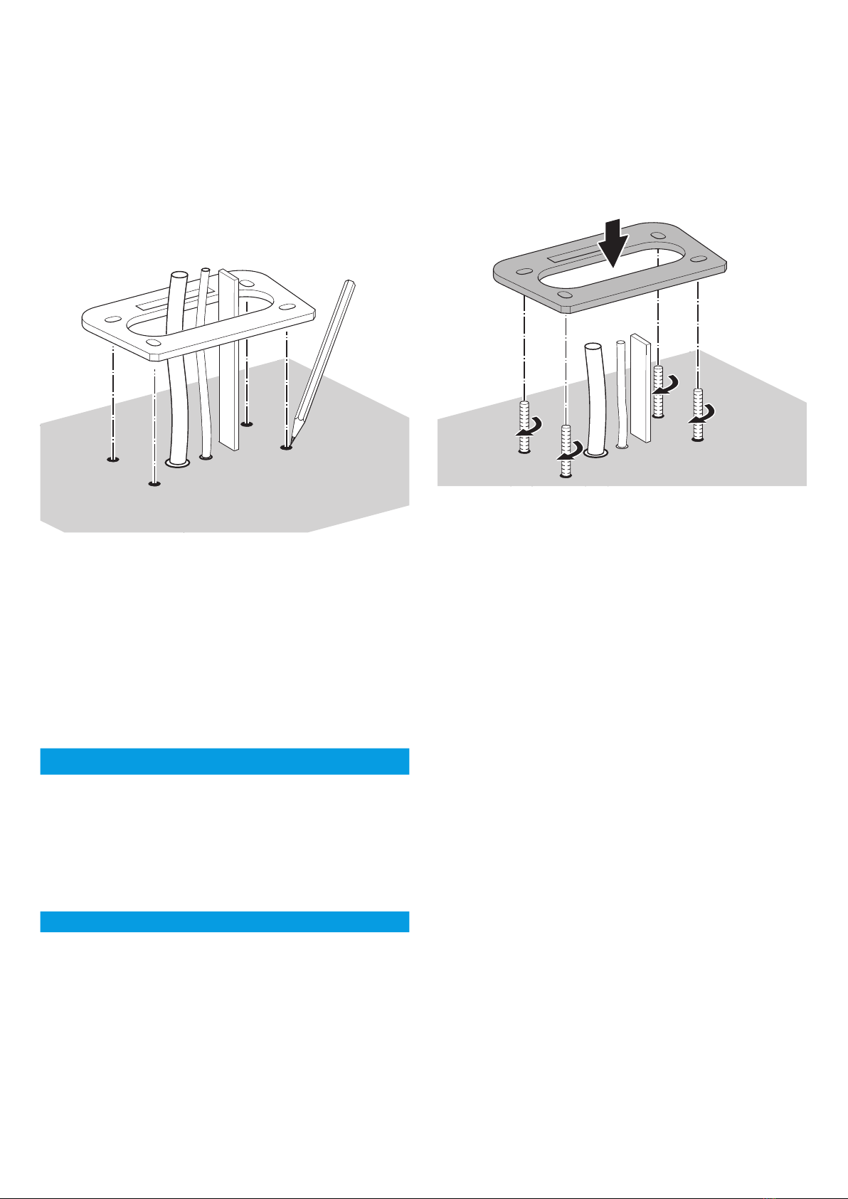
4.2.2 Using an existing foundation
fFeed the supply cable and, if applicable, the BUS cable
through the floor panel (accessory).
fPlace the floor panel on the existing concrete
foundation.
fLevel out the floor panel as appropriate.
fMark out the drill holes on the foundation.
TCAUTION
Risk of rust damage to the floor panel!
The powder coating may be damaged if you drill through
the floor panel.
fOnly use the floor panel as a template to mark out the
drill holes.
fDrill the holes in the foundation.
fUse suitable heavy-duty dowels.
The required heavy-duty dowels depend on different
factors such as the concrete quality, depth of the
foundation, etc.
If in doubt, consult a technical expert.
fPlace the floor panel in position.
fLevel out the floor panel accordingly and screw down
using nuts.
fMount the charging column.
See installation manual of the chargin column.
7
ENEN
The dimensions of the floor panel and of the foundation set are different depending on the size of the charging column.
According to the article number of the charging column, you can figure out the size of your charging
column and which floor panel or foundation set you have to use.
Charging columns Basic Premium,
Smart (S) Smart N / SN Smart T / ST
Article number charging column 3115xx
13115xx
3136xx
3196xx
13136xx
13196xx
3164xx
3165xx 3166xx
Size [mm] 1300 1380 1580 1775
Article number floor panel 18514 18514 18515 18567
Article number foundation set 18516 18516 18517 18517
* x is an arbitrary number
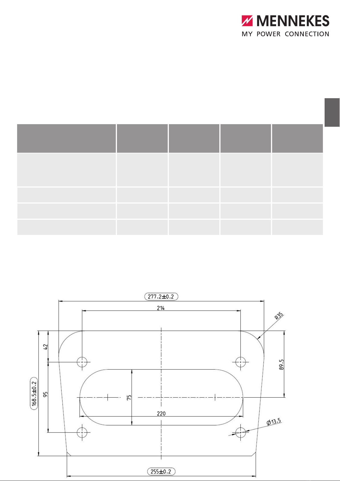
Dimensions of the floor panel with the article number 18514
t = 20
5. Dimensions

8
Dimensions of the floor panel with the article number 18515
t = 20

9
ENEN
Dimensions of the floor panel with the article number 18567
t = 20
I
u-
·s·
Floor panel 1300 / 1380 mm
f�
1580
1300 / 1380
a
a,
-·
1024389
Foundation for charging columns
Basic, Premium, Smart (S / N / SN)
Floor panel 1580 mm
Foundation set 1300 / 1380 mm
Foundation set 1580 mm

G
1
N
N
2 3 4 5 6
=
N
=
N
7
8
9
f
B
.
0 0
1
B
Q
a MENNEKES® 1112296,P2D ,DRW ,00
15-536
n
s s s
1112296
F
Foundation for charging
columns Smart T / ST

MENNEKES
Elektrotechnik GmbH & Co. KG
Spezialfabrik für
Steckvorrichtungen
Aloys-Mennekes-Str. 1
57399 Kirchhundem, Germany
Tel. +49 (0) 2723 / 41-1
Fax +49 (0) 2723 / 41-2 14
E-mail [email protected]
Internet www.MENNEKES.de
IA_Fundament LS_v03_11-04-2018_en
This manual suits for next models
6
Table of contents
Other Mennekes Batteries Charger manuals

Mennekes
Mennekes AMTRON Compact 2.0s 7,4 Specification sheet

Mennekes
Mennekes AMTRON Xtra E User manual

Mennekes
Mennekes Basic 3,7 Specification sheet

Mennekes
Mennekes AMTRON Compact 2.0 7,4 Specification sheet

Mennekes
Mennekes Premium 3,7 Specification sheet

Mennekes
Mennekes AMTRON Start E User manual

Mennekes
Mennekes AMTRON Compact 2.0s 11 Specification sheet

Mennekes
Mennekes AMTRON Compact 2.0 11 Specification sheet

Mennekes
Mennekes AMTRON Start E User manual

Mennekes
Mennekes Basic 3,7 User manual


