Aertesi BREZZA DOUBLE Series User manual

Technical Manual
New Water Cassette
Series BREZZA DOUBLE

AERTESI srl Cassetta BREZZA DOUBLE Tecnical manual
AER.MT.I.BREDOPPIA.000.02.15 Pag.2

INDEX
1-INTRODUCTION………………………………………………………………………………………………………………………4
2- WORKING CONDITION LIMITS……………………………………………………………………………………….……….4
3- COANDA EFFECT…………………………………………………………………………………………………………………….4
4- KEY READING CODES………………………………………………………………………………………………………………5
5-TECHNICAL DETAILS………………………………………………………………………………………………………………..6
6-TECHNICAL DATA (AC motors)…………………………………………………………………………………………………8
6.1-Cassette with 3 rows coil............................................................................................................... 8
7-TECHNICAL DATA(EC motors)………………………………………………………………………………………………….9
7.1-Cassette with 3 rows coil............................................................................................................... 9
8- COIL TECNICAL DATA(AC motors)………………………………………..……………………………………………….10
8.1- Cassette with 1 or 2 rows coil ..................................................................................................... 10
9-TECHNICAL DATA OPTIONAL COILS (EC motor)………………………………………………………………………11
9.1- Cassette with1 or 2 rows coil ...................................................................................................... 11
10-DIMENSIONAL & WEIGHT…..……………………………………………………………………………………………….12
11-ACCESSORIES………………………………………………………………………………………………………………………13
11.1- Valves (V) and auxiliary tray (ADPB).......................................................................................... 13
11.2- Hose connecting valves (Flex2 and Flex4) .................................................................................. 15
11.3- Condensate drain pump Auxiliary (PSCC-BI) .............................................................................. 16
11.4- Speed motor control board....................................................................................................... 16
11.5- Flange for air delivery duct (FLMA) ........................................................................................... 19
11.6-Flange for external air intake (FLAE-FLAE2) ............................................................................... 19
12-Electrical wiring diagrams……………………………………………………………………………………………………20
12.1- Wiring diagram cassette with AC motor .................................................................................... 20
12.2-Wiring diagram cassette with EC motor ..................................................................................... 22
1-INTRODUCTION
The new Water Cassette Series units BREZZA are designed for air conditioning in residential and
commercial plants. The installation is indoor and not exposed to ice or extreme temperatures, dust-free
environment and not explosive materials. The manufacturer is not responsible in case of incorrect use.
The series BREZZA is proposed with traditional AC motors with three speeds and which EC motors with low
consumption. The table below shows the electric power saving that can be achieved with EC motors (at
constant working point of the machine).
2- WORKING CONDITION LIMITS
Electrical power supply
220 ÷ 240V / 50Hz
Inletcoil water temperature
5 ÷ 70°C
Return air temperature
10 ÷ 50°C
RH air intake
15 ÷ 70%
It is advisable to let work the Brezza Cassette at the above mentioned extremes limits of operation ONLY for
short periods, because the operation for long periods can reduce normal components.
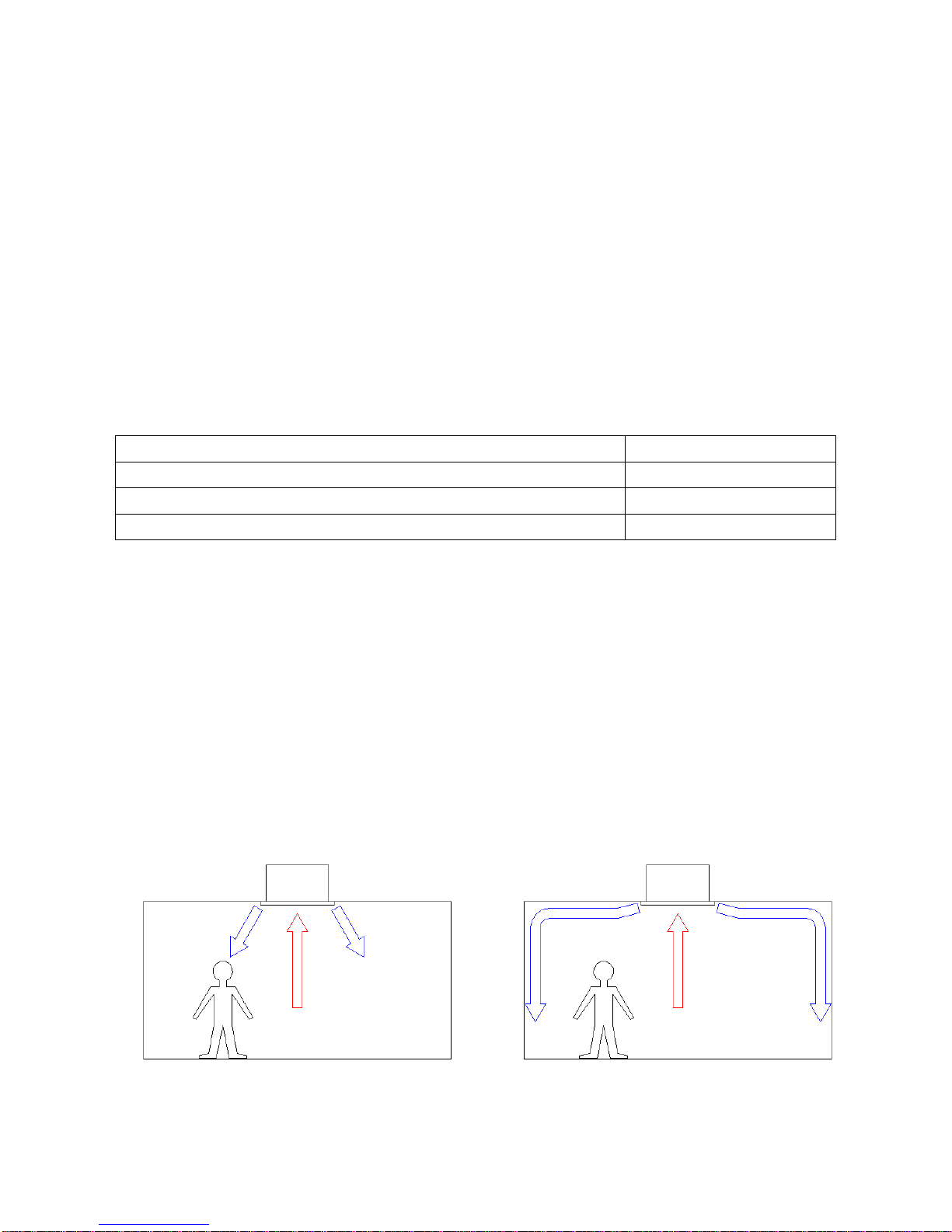
3- COANDA EFFECT
New cassette Series BREZZA has been developed to ensure a high comfort. In fact, the particular shape of
the panel as per the COANDA effect, avoids the annoying cold drafts (since ever the problem of fan-coil
cassettes).
The COANDA effect is the tendency of a fluid jet to follow the contour of a nearby surface. So the air flow
follows the ceiling, then fells nearly at the wall. Since the air speed at this point is very low, this does not
create discomfort to people.
Traditional Cassette Cassette with Coanda effect

In case where the ceiling is higher than 3m, accordingly there is the need to channel down the air flow,
Aertesi provides an accessory panel with adjustable flaps. So you can set manually, for each of the four
turns, the orientation of the flow: horizontal (with Coanda effect), or in vertical position.
Flaps on horizontal position (Coanda) Flaps on vertical position
4- KEY READING CODES
The standard version is with 3-rows coil (for versions 2 pipes) or 1 + 2 ranks (for versions 4 pipes), with fixed
blades in COANDA position. All other versions are optional.

5-TECHNICAL DETAILS
STRUCTURE: made on galvanized steel sheet, thickness 1.00mm. The robust design prevents the vibration
and it includes mounting brackets to the ceiling.
FRONTAL PANEL: painted plate thickness 0.8mm. The conformation of the baffles ensures a Coanda Effect
to the air flow output. As an accessory, you can have the adjustable deflectors to have the Coanda effect or
vertical airflow (or intermediate positions). The fresh design of the panel fits perfectly into any environment
and type of ceiling.
ACCESSIBILITY : the filter can be removed without any tools. The accessibility to internal components (fan
and condensate pump) is guaranteed by removing the front panel. Water connections, valves and electrical
panel are on the same side and thus you need only one inspection hatch in the ceiling.
FILTER: Class G1 (EN779), 6 mm thickness, made in polypropylene mesh.
FAN GROUP: The fan is made of reinforced plastic material (nylon PA6-25GF); it is backward curved blades,
directly coupled to the motor. The motor and fans are balanced after assembly to ensure, vibrations
absence. Motor is mounted on ball bearings without any maintenance.
The AC motor has three speed, degree of protection IP44, insulation class "B". Thermal protection
incorporated.
The EC motor is controlled 0-10V, IP54 protection, insulation class "B", noise emissions according to EN
61000-6-3 (civil environment), thermal motor protection and electronics, protection locked rotor.
COIL: made with copper pipe diameter 3/8 "and corrugated aluminum fins with high efficiency, with manual
air vent valve at the top. Nominal pressure PN10.
WATER TRAP: blower housing made of expanded polystyrene (EPP) with condensation molded plastic tray,
which ensures no water leakage even after a long use. The shape of the pan facilitates the outflow and
ensures minimum water stagnation.

INSULATION: cassette body insulated with cross-linked polyethylene foam 10 mm thick, class B-BL-s2d0
s1d0 according to EN13501-1. Front panel insulated with polyethylene thickness 3mm.
ELECTRICAL BOARD: made of galvanized steel plate and positioned on the same side of water
connections.
CONDENSATE DRAIN PUMP: centrifugal type, equipped with a double level float (on-off pump and alarm)
and check valve (to avoid the return of odors from the plughole and reduce the noise power). The maximum
head of the pump is 650mm, measured from the edge of the panel.

6-TECHNICAL DATA (AC motors)
6.1-Cassette with 3 rows coil
2 TUBI
4 TUBI
133
163
135
165
Speed(E)
min
med
max
min
med
max
min
med
max
min
med
max
Airflow
mc/h
560
800
1140
860
1260
1470
560
800
1140
860
1260
1470
COOLING –Air 27°C b.s. , 19°C b.u. –Input water temperature 7°C , output water temperature 12°C
Total capacity(E)
kW
4,11
5,51
7,46
5,88
8,10
9,16
3,52
4,75
6,23
5,00
6,69
7,47
Sens. capacity(E)
kW
2,94
4,00
5,30
4,25
5,72
6,44
2,57
3,37
4,36
3,58
4,68
5,20
Water flow
l/h
706
946
1279
1008
1389
1571
603
815
1069
859
1148
1281
Δp water(E)
kPa
3,3
5,6
9,8
6,3
11,3
14,1
3,8
6,4
10,5
7,0
12,0
14,6
HEATING –Air 20°C –inlet water temperature 50°C ,same for cooling flow
Capacity(E)
kW
4,79
6,50
8,71
6,91
9,44
10,66
-
-
-
-
-
-
Water flow
l/h
706
946
1279
1008
1389
1571
-
-
-
-
-
-
Δp water(E)
kPa
3,1
5,3
9,2
6,0
10,7
13,4
-
-
-
-
-
-
HEATING –Air 20°C - inlet water temperature 70°C , output water temperature 60°C
Capacity(E)
kW
-
-
-
-
-
-
5,25
6,69
8,47
7,03
8,96
9,90
Water flow
l/h
-
-
-
-
-
-
476
606
767
637
811
896
Δp water(E)
kPa
-
-
-
-
-
-
3,5
5,5
8,3
6,0
9,2
11,2
ELECTRIC MOTOR ABSORTION
Consumption(E)
W
60
76
100
108
144
174
60
76
100
108
144
174
Max absorption
A
0,46
0,80
0,46
0,80
SOUND DATA
Sound power(E)
dB(A)
39
46
56
53
63
66
39
46
56
53
63
66
Sound pressure
dB(A)
30
37
57
44
54
57
30
37
57
44
54
57
(E)= EUROVENTcertificated data
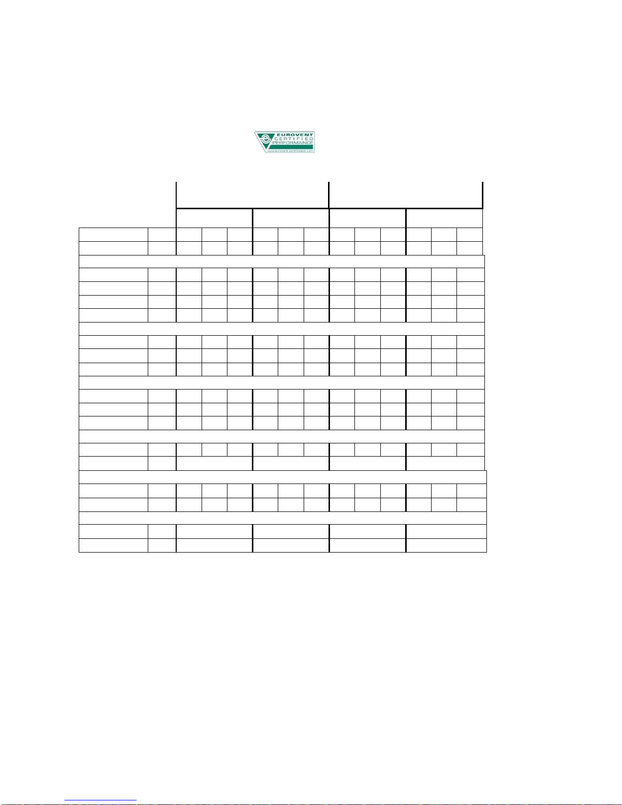
7-TECHNICAL DATA(EC motors)
7.1-Cassette with 3 rows coil
2 PIPES
4 PIPES
133
163
135
165
Speed(E)
4V
7V
10V
4V
7V
10V
4V
7V
10V
4V
7V
10V
Airflow
mc/h
410
760
1120
570
1050
1520
410
760
1120
570
1050
1520
COOLING –Air 27°C d.b. , 19°C w.b.. –inlet water temperature 7°C , output water temperature 12°C
Total capacity(E)
kW
3,11
5,28
7,35
4,17
6,96
9,42
2,61
4,56
6,13
3,58
5,83
7,66
Sens.capacity(E)
kW
2,19
3,85
5,22
2,99
4,95
6,60
1,98
3,25
4,29
2,61
4,09
5,35
Water flow
l/h
534
905
1260
716
1195
1616
448
783
1052
614
1001
1315
Δp water(E)
kPa
2,1
5,3
9,4
3,5
8,6
14,8
2,2
6,0
10,1
3,9
9,3
15,3
HEATING –Air 20°C –inlet water temperature 50°C , same for cooling flow
Capacity(E)
kW
3,60
6,24
8,57
4,87
8,12
10,95
-
-
-
-
-
-
Water flow
l/h
534
905
1260
716
1195
1616
-
-
-
-
-
-
Δp water(E)
kPa
1,8
4,9
9,0
3,3
8,2
14,2
-
-
-
-
-
-
HEATING –Air 20°C - inlet water temperature 70°C , output water temperature 60°C
Capacity(E)
kW
-
-
-
-
-
-
4,16
6,47
8,29
5,32
7,96
10,16
Water flow
l/h
-
-
-
-
-
-
377
586
751
481
721
919
Δp water(E)
kPa
-
-
-
-
-
-
2,2
5,1
8,1
3,5
7,4
11,7
ELECTRIC MOTOR ABSORTION
Consumption(E)
W
6
18
42
10
36
97
6
18
42
10
36
97
Max absorption
A
0,34
0,76
0,34
0,76
DATI SONORI
Sound power(E)
dB(A)
34
48
59
41
57
66
34
48
59
41
57
66
Sound pressure
dB(A)
25
39
50
32
48
57
25
39
50
32
48
57
ENERGY SAVING CLASS
FCEER (E)
A
A
A
A
FCCOP(E)
A
A
A
A
(E)= EUROVENT certificated data
8- OPTIONAL COIL TECNICAL DATA(AC motors)
8.1- Cassette with 1 or 2 rows coil
2 PIPES
4 PIPES
132
162
134
164
Speed
min
med
max
min
med
max
min
med
max
min
med
max
Airflow
mc/h
560
800
1140
860
1260
1470
560
800
1140
860
1260
1470
COOLING –Air 27°C d.b. , 19°C w.b.. –inlet water temperature 7°C , output water temperature 12°C
Total capacity
kW
3,37
4,53
5,94
4,80
6,39
7,12
2,28
2,94
3,73
3,12
3,99
4,40
Sens.capacity
kW
2,49
3,26
4,20
3,44
4,52
5,02
1,67
2,14
2,67
2,22
2,86
3,11
Water flow
l/h
578
778
1019
824
1096
1221
391
504
640
535
684
754
Δp water
kPa
3,2
5,5
9,0
6,1
10,2
12,4
2,9
4,5
6,9
4,9
7,8
9,3
HEATING –Air 20°C –inlet water temperature 50°C , same for cooling flow
Capacity
kW
4,12
5,45
7,10
5,76
7,63
8,53
-
-
-
-
-
-
Water flow
l/h
578
778
1019
824
1096
1221
-
-
-
-
-
-
Δp water
kPa
3,0
5,2
8,6
5,9
9,8
12,0
-
-
-
-
-
-
HEATING –Air 20°C - inlet water temperature 70°C , output water temperature 60°C
Capacity
kW
-
-
-
-
-
-
5,25
6,69
8,47
7,03
8,96
9,90
Water flow
l/h
-
-
-
-
-
-
476
606
767
637
811
896
Δp water
kPa
-
-
-
-
-
-
3,5
5,5
8,3
6,0
9,2
11,2
ELECTRIC MOTOR ABSORTION
Consumption
W
60
76
100
108
144
174
60
76
100
108
144
174
Max absorption
A
0,46
0,80
0,46
0,80
SOUND DATA
Sound power
dB(A)
39
46
56
53
63
66
39
46
56
53
63
66
Sound pressure
dB(A)
30
37
57
44
54
57
30
37
57
44
54
57

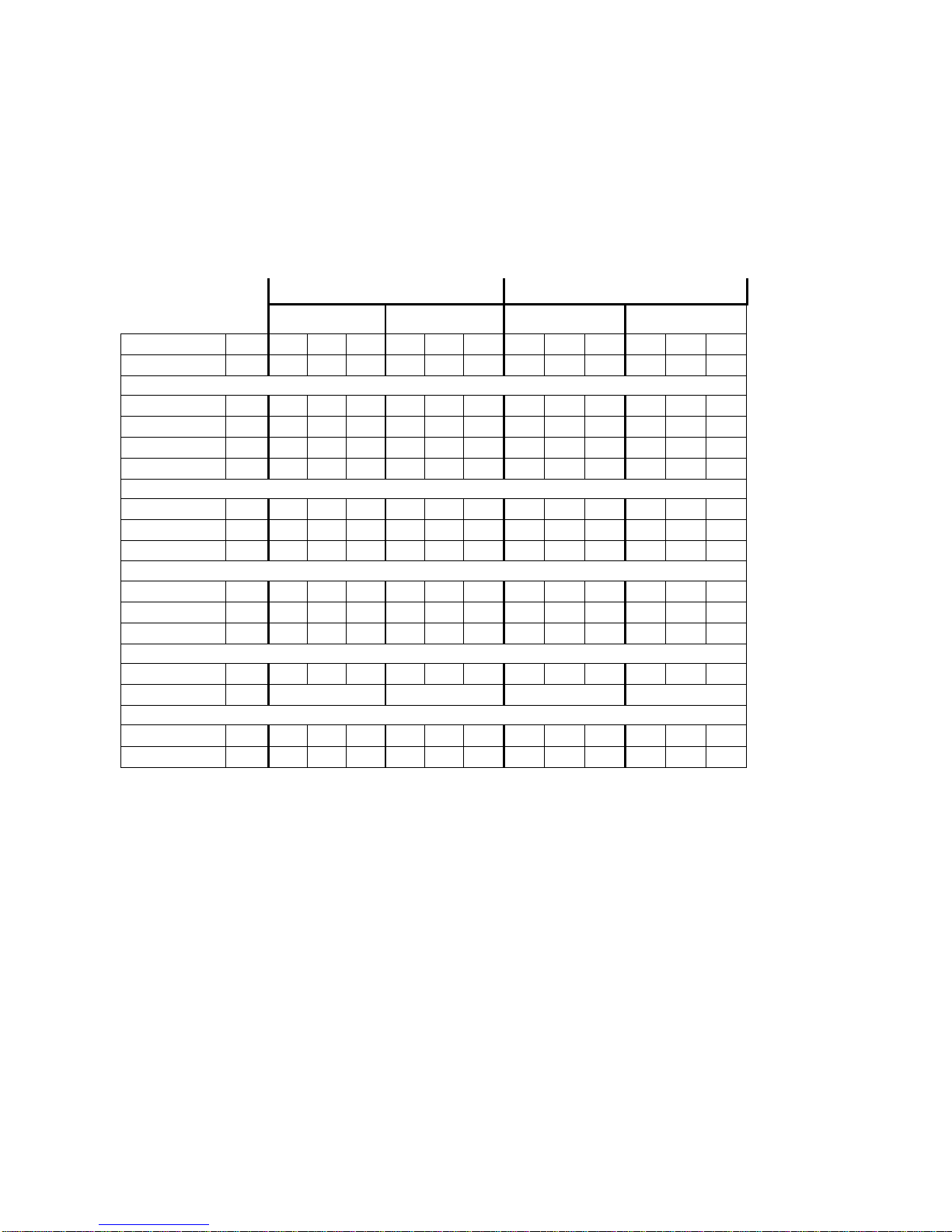
9-TECHNICAL DATA OPTIONAL COILS (EC motor)
9.1- Cassette with1 or 2 rows coil
2 PIPES
4 PIPES
132
162
134
164
Speed
4V
7V
10V
4V
7V
10V
4V
7V
10V
4V
7V
10V
Airflow
mc/h
410
760
1120
570
1050
1520
410
760
1120
570
1050
1520
COOLING –Air 27°C d.b. , 19°C w.b.. –inlet water temperature 7°C , output water temperature 12°C
Total capacity
kW
2,46
4,38
5,85
3,43
5,57
7,30
1,75
2,86
3,68
2,32
3,53
4,51
Sens.capacity
kW
1,92
3,13
4,14
2,52
3,96
5,12
1,34
2,07
2,64
1,69
2,50
3,19
Water flow
l/h
423
751
1004
588
956
1253
299
491
632
398
606
774
Δp water
kPa
1,8
5,2
8,7
3,3
7,9
13,0
1,7
4,3
6,8
3,0
6,2
9,8
HEATING –Air 20°C –inlet water temperature 50°C , same for cooling flow
Capacity
kW
3,16
5,25
7,00
4,18
6,65
8,73
-
-
-
-
-
-
Water flow
l/h
423
751
1004
588
956
1253
-
-
-
-
-
-
Δp water
kPa
1,7
4,8
8,3
3,1
7,5
12,5
-
-
-
-
-
-
HEATING –Air 20°C - inlet water temperature 70°C , output water temperature 60°C
Capacity
kW
-
-
-
-
-
-
4,16
6,47
8,29
5,32
7,96
10,16
Water flow
l/h
-
-
-
-
-
-
377
586
751
481
721
919
Δp water
kPa
-
-
-
-
-
-
2,2
5,1
8,1
3,5
7,4
11,7
ELECTRIC MOTOR ABSORTION
Consumption
W
6
18
42
10
36
97
6
18
42
10
36
97
Max absorption
A
0,34
0,76
0,34
0,76
SOUND DATA
Sound power
dB(A)
34
48
59
41
57
66
34
48
59
41
57
66
Sound pressure
dB(A)
25
39
50
32
48
57
25
39
50
32
48
57
ENERGY SAVING CLASS
FCEER
A
A
A
B
FCCOP
A
B
A
A

10-DIMENSIONAL & DRAWINGS
132/162
133/163
134/164
135/165
Unit gross Weight
kg
56
60
56
60
Internal volume main coil
litri
2,6
4,0
2,8
2,8
Internal volume auxiliary coil
litri
-
-
1,2
1,2
1
Batteria principale IN
1/2"
2
Batteria principale OUT
1/2"
3
Batteria ausiliaria IN
1/2"
4
Batteria ausiliaria OUT
1/2"
5
Scarico condensa
d.12

11-ACCESSORIES
Accessories available are:
HYDRAULIC ACCESSORIES
A/K/C
V22
V22 2-way valve ON-OFF 230V
A/K
V42
V42 2-way valve ON-OFF for 4 pipe
A/K
V23
V23 3-way valve ON-OFF 230V
A/K
V43
V43 3-way valve ON-OFF 230V for 4 pipe
A/K
V22M
V22M Valve 2-way modulating 0-10V
A/K
V42M
V42M Valve 2-way modulating 0-10V for 4 pipe
A/K
V23M
V23M valve 3 way modulating 0-10V
A/K
V43M
V43M valve 3 way modulating 0-10V for 4 pipe
A/K
ADPB
ADPB Water trap auxiliary (supplied as standard)
K
FLEX2
Hoses for parallel connection valves (2 pipes)
K
FLEX4
Hoses for parallel connection valves (4 pipes)
K
PSCC-BI
PSCC-BI Auxiliary Condensate drain pump
A
ELETTRICAL ACCESSORIES
TR24
Transformer 230Vac-24VAC, 20VA for modulating valve
A
SC3
3-speed motor control board (for EC motor)
A
AERAULIC ACCESSORIES
FLMA
Flange for discharge air duct
B
FLAE
Flange for fresh air intake
B
A = accessory supplied mounted on the base;
K = accessory kit supplied unassembled;
B = accessory supplied assembled, but not mounted on the base
11.1- Valves (V) and auxiliary tray (ADPB)
We recommend the use of motorized valves, to prevent the formation of condensation on the surface of the
unit when the fan is stopped.

Valves can be supplied to the unit assembled or in kit (disassembled parts). All codes kits include two
valves, one for each battery in double cassette. The drain pan is supplied as standard with the cassette,
without extra-price (ADPB)
The cassette have two double 1200x600 kit valves, one for the right battery and one for the left battery. Both
kits valves are connected in parallel, the aim is a kit consisting of hoses and TEE brass (see paragraph on
accessory Flex2 - Flex4).
OUT IN OUT IN
2 pipes (hot/cold) 2 pipes (not present)
4 pipes (cold) 4 pipes (hot)
Valves group and auxiliary tray (cassette double 1200x600)
Heating/cooling valve (2 pipes)
Valve cooling (4 pipes)
Hot valve (only
4 pipes)
Heating/cooling valve (2
pipes)
Valve cooling (4 pipes)
Valve cooling (4 pipes)
Hot valve (only
4 pipes)
Auxiliary drain pan

VALVES FOR MAIN COILS
---
132-133-134-135-162-
163-164-165
VALVES FOR AUXILIARY COILS
134-135-164-165
---
GENERAL FEATURES
Size connections
1/2"
3/4"
Kv (valvola 2 vie)
1,7
2,5
Kv (valvola 3 vie, via diritta)
1,7
2,5
Kv (valvola 3 vie, by-pass)
1,2
1,6
Max differential pressure
2,0bar
1,0bar
Nominal pressure
16bar
Nominal pressure
4-110°C
ON-OFF ACTUATOR
Power supply
230V-50Hz (24V-50Hz on request)
Power consumption
2,5W
Running time
180s
Feature (valve + actuator) N.C.
N.C. (usually closed)
Protection
IP44
MODULAT ACTUATOR
Electrical supply
24V-50Hz
Power consumption
1,5W
Travel time
8S
Control signal
0-10V
Impedance control signal
100k
Protection
IP43
11.2- Hose connecting valves (Flex2 and Flex4)
To facilitate the parallel connection of the valves, described in the previous paragraph, you can use the
accessory Flex2 (for 2-pipe systems) and Flex4 (for 4-pipe systems). The kit consists of hoses with braided
stainless steel (with 3/4 "for the valve) and brass TEE to connect the pipes from 3/4". You can also directly
connect the hoses to the coil, inserting an adaptor nipple 1/2 "-3/4" (nipple not supplied).
BRASS TEE
FLEX INOX
Accessory for flexible double cassette 1200x600

11.3- Condensate drain pump Auxiliary (PSCC-BI)
The supplementary condensate drain pump is supplied assembled outside of the box, at the side of the
drainage pipe. Then must provide for the possibility of inspection also on this side.
Maximum water flow
20 l/h
Maximum discharge height
10m (4l/h)
Sound pressure 1m
28dB(A)
Supply
230V –50/60Hz
Micro switch alarm
NC 8° resistivi 250V
Thermal Protection
90°C (riarmo automatico)
Protection
IP54
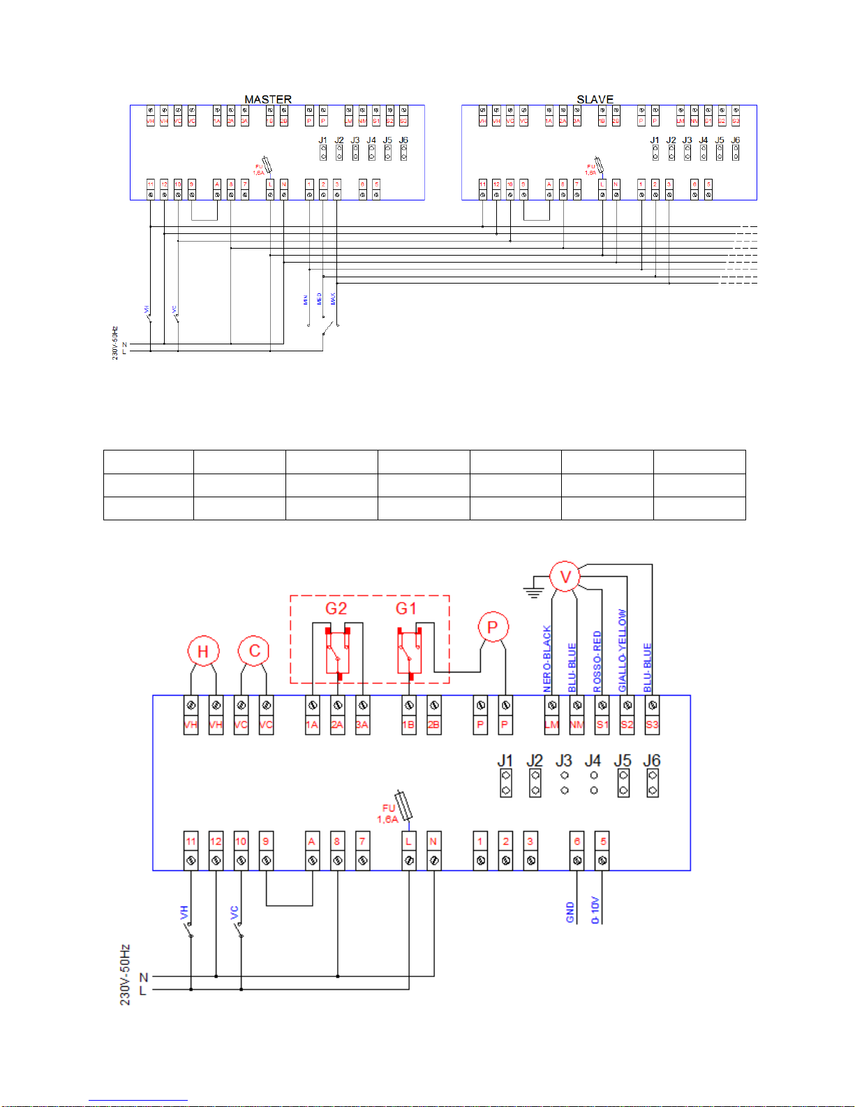
11.4- Speed motor control board SC3
The 3-speed motor board allows you to control the EC motor with a traditional thermostat 3-speed or with a
thermostat with 0-10V signal. With this accessory, it is also possible to control more than one unit with a
single thermostat (not addressable master-slave).
For each double cassette, you need two cards SC3 (to be considered as a slave of the other).
CONTROL FROM EXTERNAL THERMOSTAT
VH
Contact on-off valve heating (4 tubes)
VC
Contact on-off valve cooling (2-4 tubes)
MIN
Minimum fan speed
MED
Minimum fan speed
MAX
Maximum speed fan
GND
Reference signal 0-10V
0-10V
0-10V signal for motor control

ELECTRICAL CONNECTIONS FOR 3 SPEEDSCONTROL : you must close the jumpers J3 and J4; jumpers
J1, J2, J5, J6 are reserved to factory settings and should not be changed.
Model
J1
J2
J3
J4
J5
J6
7x-13x
opened
closed
closed
closed
closed
closed
9x-16x
closed
opened
closed
closed
closed
closed
ELECTRICAL CONNECTIONS FOR CONTROL SIGNAL 0-10V: you must open the jumpers J3 and J4;
jumpers J1, J2, J5, J6 are reserved to factory settings and should not be changed.
Model
J1
J2
J3
J4
J5
J6
7x-13x
closed
closed
opened
opened
opened
opened
9x-16x
closed
closed
opened
opened
closed
opened

11.5- Flange for air delivery duct (FLMA)
You can connect up to 3 throws ducted through D.160 collars. The available prevalence is a function of the
number of collars connected and the air flow rate. Collars positions are represented in the figure below.
11.6- Flange for external air intake (FLAE-FLAE2)
It is possible to connect an external air intake via a D.100 collar. The maximum flow of outside air is
100MC/h. The outside air has to be treated, filtered and must not be at a low temperature.
The flange for fresh air intake has FLAE code or FLAE2 code. These have different installation points on the
unit, as in the drawing below.
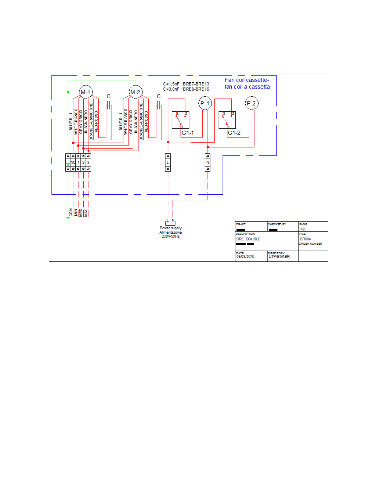
12-Electrical wiring diagrams
12.1- Wiring diagram cassette with AC motor
Table of contents
Other Aertesi Air Conditioner manuals


Popular Air Conditioner manuals by other brands

Soleus Air
Soleus Air KC-15U owner's manual

Retro Aire
Retro Aire R30C Installation, operation & maintenance manual

CLIMAVENETA
CLIMAVENETA a-CHD U-2T 606+2209 OPERATING AND INSTALLATION Manual

GE
GE AEC14 Owner's manual and installation instructions

Rotenso
Rotenso MIRAI W user manual

McQuay
McQuay MCK020A Technical manual


