Aertesi ECOELEGANT SERIES User manual
NA version 2.1
Revised: Feb. 17, 2014 AER.MIU.HWNEC.GB.01.04/14
AERTESI srl
Via della tecnica 6
35020 Conselve- PD
ITALY
www.aertesi.com
ECOELEGANT SERIES
INSTALLATION AND OPERATION MANUAL
HWN-EC SERIES

Page 2 of 36
AER.MIU.HWNEC.GB.01.04/14
INVESTING IN QUALITY, RELIABILITY & PERFORMANCE.
ISO 9001 QUALITY
World Leading Design and Technology
Every product is manufactured to meet
the stringent requirements of the
internationally recognized ISO 9001
standard for quality assurance in design,
development and production.
Equipped with the latest CAD/CAM computer aided
design and manufacturing technology, our factories in
produce thousand of air conditioning units each year,
all conforming to the highest international standards
of quality and safety.
CE SAFETY STANDARDS
The Highest Standards of Manufacturing
All products conform to the Certificate
Europe directives (Machinery Safety,
Electromagnetic Compatibility and Low
Voltage), as required throughout the
European Community, to guarantee
correct standards of safety.
In order to guarantee the very highest standards and
performance, we manage every stage in the
manufacturing of our products. Throughout the
production process we maintain strict control, starting
with our extensive resources in research and
development through to the design and manufacture
of almost every individual component, from molded
plastics to the assembly of units and controllers.
WEEE MARK
Quality Controlled from Start to Finish
All products conform to the directive to
guarantee correct standards of
environmental solutions.
Our highly trained staff and strict quality control
methods enable us to produce products with an
exceptional reputation for reliability and efficiency,
maintained over many years. As well as full CE
certification and ISO 9001, several products have
UL/ETL/CSA (NRTL) safety approval plus ARI
Certification in the USA and Canada, in addition to
ROHS compliance for Europe, giving you the
confidence of knowing our company is the right choice
when selecting air conditioning equipment.
ALWAYS MAKE SURE THIS MANUAL REMAINS WITH THE SWC-AECM WATER HIGH-WALL UNIT. READ THIS MANUAL
BEFORE PERFORMING ANY OPERATION ON THE SWC-AECM WATER HIGH-WALL UNIT.

Page 3 of 36
AER.MIU.HWNEC.GB.01.04/14
Table of Content
A. TECHNICAL DATA....................................................................................................................4
A.1. GENERAL DESCRIPTION .....................................................................................................................4
A.2. GENERAL SPECIFICATION ...................................................................................................................5
A.2.1. HWN–EC Series 3-Speed Specifications...................................................................................................5
A.3. DIMENSIONAL DRAWINGS .................................................................................................................7
B. SERVICE AND INSTALLATION ...................................................................................................7
B.1. INSTALLATION OF HIGH-WALL UNIT......................................................................................................7
B.1.1. Selecting a Location .............................................................................................................................. 7
B.1.2. Mounting Plate Dimensions...................................................................................................................8
B.1.3. Installing the Mounting Plate.................................................................................................................8
B.1.4. Drilling the Condensate Drainage Hole ...................................................................................................9
B.1.5. Installing the Hydronic Unit ...................................................................................................................9
B.1.6. Drainage Piping Works ..........................................................................................................................9
B.2. UNIT MAINTENANCES AND PREPARATIONS ...........................................................................................10
B.2.1. Opening and Closing Of Lift-Up Grille Cover..........................................................................................10
B.2.2. Removing Front Cover Assembly..........................................................................................................10
B.2.3. Air Purging .........................................................................................................................................11
B.2.4. Wiring Connections ............................................................................................................................11
B.3. PIPE CONNECTIONS WITH VALVE........................................................................................................11
C. CONTROL SPECIFICATIONS ....................................................................................................11
C.1. EBWPCGH –EC COMPLETE FUNCTION FCU CONTROLLER........................................................................11
C.1.1. Abbreviations.....................................................................................................................................11
C.1.2. Definition of Input/Output ..................................................................................................................11
C.1.3. Wiring Diagram EBWPCGH-EC .............................................................................................................13
C.1.4. Configuration Settings.........................................................................................................................14
C.1.5. Control Logics for 2-Pipe System ..........................................................................................................15
C.1.6. Control Logics for 4-Pipe System ..........................................................................................................17
C.1.7. Auto Fan Speed ..................................................................................................................................19
C.1.8. Louver ...............................................................................................................................................19
C.1.9. Buzzer................................................................................................................................................19
C.1.10. Auto Restart.......................................................................................................................................19
C.1.11. Operation Of Control Panel On High-Wall Unit......................................................................................20
C.2. LED LIGHTS.................................................................................................................................21
C.2.1. LED Indication and Error Description ....................................................................................................21
C.2.2. LED Indication on Master/Slave Connection..........................................................................................22
C.3. NETWORKING SYSTEM....................................................................................................................22
C.3.1. Master-Slave Network ........................................................................................................................22
C.3.2. Master –Slave Network Setup.............................................................................................................23
C.3.3. Master-Slave Communication Method .................................................................................................24
C.3.4. Unit Network Wiring Scheme ..............................................................................................................26
C.4. SK-NCSWC-002 LIMITED FUNCTION FCU CONTROLLER (ON DEMAND) .....................................................27
C.4.1. Definition of Input/Output ..................................................................................................................27
C.4.2. Wiring Diagram SK-NCSWC-002 ...........................................................................................................28
C.4.3. Onboard Configuration .......................................................................................................................29
C.4.4. Control Logics Specification .................................................................................................................29
C.4.5. LED Indication ....................................................................................................................................30
D. USER INTERFACE...................................................................................................................31
D.1. REMOTE CONTROL HANDSET ............................................................................................................31
D.2. WIRED WALL PAD .........................................................................................................................32
D.2.1. Wall Pad Display .................................................................................................................................32
D.2.2. Wall Pad Operation Guidelines ............................................................................................................33
E. TROUBLESHOOTING GUIDE ...................................................................................................36

Page 4 of 36
AER.MIU.HWNEC.GB.01.04/14 SK2014-SON-002-TechMnl-SWC-001
A. Technical Data
A.1. General Description
This High-Wall Unit is designed to meet and exceed demanding requirements for efficiency, quiet operation and appearance. The
sleek profile and elegantly styled cabinet complements any interior design theme, while the microprocessor assures accurate
environmental control.
Cabinet ~ the stylish cabinet is constructed of durable flame resistant acrylonitrile-butadiene-styrene (ABS) plastic. The silver
white color and rounded corners provide its modern look.
Water Coil ~ the water coil has a large heat transfer surface and utilizes the latest technology in fin profiling. It combines an
advanced technology approach with the security of a traditional design regarding tube thickness. The water coil is also equipped
with an air vent valve and a water purge valve.
Integral Hoses ~ an integral hose is a synthetic elastomer tube, with stainless steel outer braiding and brass connectors,
which enables quick, low cost connections with no brazing.
Blower and Motor ~ the High-wall unit incorporates only specially designed and tested EC motors, allowing the blower wheel to
provide optimum performance in airflow-efficiency and quiet operation.
Filters ~ washable, easy-to-remove, fine mesh air filters are standard to all High-wall models. Tabs located on the front of the unit
can be unsnapped, allowing the filter to be easily slid downward and removed. No tools are required, nor any dismantling of the
equipment.
Air Grille Distribution ~ all High-wall units are equipped with both deflector blades and independent directional vanes, enabling
supply air to be automatically distributed, and air flow and direction to be customized.
Microprocessor Control ~ see C. Controls Specifications for complete control specifications and details. The main design
features include:
~ FCEER rating class: A/B.
~ FCCOP rating class: B/C.
~ High efficiency brushless DC motor with PID algorithmic processing in auto-mode.
~ 2-pipe, 2-pipe with booster electric heat, 2-pipe with primary electric heat, 4-pipe with 4x2 device installed.
~ Cool, Heat, Auto, Dehumidifier and Fan modes.
~ Sleep, Auto-Fan, Daily Timer, Auto-Restart with memory functions.
~ User friendly remote control handset.
~ Heat and cool temperature protections and safety cut out.
~ 2-way and 3-way on/off valve control.
~ Addressable control and error diagnostics (Master-Slave) for sub-networks of up to 32 units, with IR handset as global
control interface.
~ Wired wall pad controller (optional) with 7-day programmable timer, real-time clock, network control (global and
addressable) and error diagnostics.
~ Manual control panel in cabinet.
~ Auxiliary switch for cooling and heating signal.
~ Occupancy (remote on/off) contacts / economy mode contacts.
~ Open Modbus communication protocol.
~ Local PC host control solution (optional).

Page 5 of 36
AER.MIU.HWNEC.GB.01.04/14 SK2014-SON-002-TechMnl-SWC-001
A.2. General Specification
A.2.1.HWN–EC Series 3-Speed Specifications
Product range: HWN-EC Hydronic High Wall with EC Motor
HWN-EC Hydronic High Wall 2-pipe with EC Motor
HWN-EC
N.A.
N.A.
25
30
Unit Configuration
Configuration
2-pipe
Number Of Fan Blowers
Single
Power Supply
(V/Ph/Hz)
230/1/50
220/1/60
Operation Control
~S: Complete function onboard PCB with integrated group control functionality, incl. 1 pc return air sensor and
2 pcs temperature sensors.
~W: Limited function onboard PCB with drain-pump, louver and zone control functionality, incl. 1 pc coil
temperature sensors.
Performance Data
Air
Total Air Flowe
H
m3/hr
370
500
500
645
M
290
370
370
445
L
220
290
290
370
Cooling
Cooling Capacitye
H
kW
1.24
2.07
2.49
3.02
M
1.04
1.64
1.86
2.4
L
0.841
1.37
1.61
1.94
Sensible Cooling Capacitye
H
0.915
1.52
1.81
2.22
M
0.766
1.2
1.34
1.47
L
0.615
0.992
1.15
1.4
FCEERe
Rating
135
168
195
187
Class
B
B
A
A
Heating
Heating Capacitye
H
kW
1.62
2.70
3.21
3.93
M
1.35
2.12
2.37
2.61
L
1.09
1.75
2.03
2.48
Max. Electric Heater Capacity
1
FCCOPe
Rating
176
216
248
230
Class
B
B
B
B
Sound
Sound PressureLevel( Outlet )
dB(A)
27/24/23
37/30/26
37/30/26
43/34/29
Sound Power Level ( Outlet )e
38/35/33
48/40/35
48/40/35
53/43/38
Electrical
Fan Motor Powere
H
W
10
13
13
20
M
8
10
10
13
L
6
8
8
10
Fan Motor Apparent Power @ H
2
32
32
50
Fan Motor Running Current @ H
A
0.08
0.142
0.142
0.182
Hydraulic
Cooling Water Flow Rate
H
L/h
212
355
427
525
M
178
281
319
411
L
144
235
276
332
Cooling Pressure Drope
H
kPa
18.3
22
28
39.3
M
13.6
15
17.1
19.9
L
9.5
11
13.4
18.4
Heating Water Flow Rate
@H/M/L
L/h
Same as "Cooling Water Flow Rate"
Heating Pressure Drope
H
kPa
14.7
18.1
22.7
31.8
M
11
11.9
13.5
15.9
L
7.56
8.7
10.7
14.8
Water Content
L
0.045
0.0789
0.124
0.124
Construction
and Packing Data
Water
Connections
Type
Socket (Threaded Female)
In
mm [in]
12.70 [1/2]
Out
Condensate Drainage Connection
16 [0.63]
Dimensions
L
mm
876
W
228
H
300
Net Weight
Kg
11
12
13
13
1."e" refers to technical information listed on the Eurovent website. Eurovent testing conditions:
a. Cooling mode (2-pipe):
b. Heating mode (2-pipe):
- Return air temperature: 27C DB/ 19C WB.
- Return air temperature: 20C.
- Inlet/ Outlet water temperature: 7C/ 12C.
- Inlet water temperature: 50C.
- Water flow-rate: same as 2-pipe cooling.

Page 6 of 36
AER.MIU.HWNEC.GB.01.04/14 SK2014-SON-002-TechMnl-SWC-001
Product range: HWS-EC Hydronic High Wall with EC Motor
HWN-EC
40
N.A.
N.A.
Unit Configuration
Configuration
2-pipe
Number Of Fan Blowers
Single
Power Supply
(V/Ph/Hz)
230/1/50
220/1/60
Operation Control
~S: Complete function onboard PCB with integrated group control functionality, incl. 1 pc
return air sensor and 2 pcs temperature sensors.
~W: Limited function onboard PCB with drain-pump, louver and zone control
functionality, incl. 1 pc coil temperature sensors.
Performance Data
Air
Total Air Flowe
H
m3/hr
788
980
1240
M
740
760
760
L
570
600
600
Cooling
Cooling Capacitye
H
kW
3.74
4.81
5.38
M
3.28
3.9
3.9
L
2.68
3.35
3.35
Sensible Cooling Capacitye
H
2.74
3.46
3.89
M
2.4
2.8
2.8
L
1.95
2.38
2.38
FCEERe
Rating
183
171
165
Class
B
B
B
Heating
Heating Capacitye
H
kW
4.87
6.10
6.85
M
4.2
4.92
4.92
L
3.45
4.19
4.19
Max. Electric Heater Capacity
1.5
FCCOPe
Rating
238
216
209
Class
B
B
B
Sound
Sound PressureLevel( Outlet )
dB(A)
46/40/34
40/35/30
45/35/30
Sound Power Level ( Outlet )e
57/52/45
52/46/41
56/46/41
Electrical
Fan Motor Powere
H
W
30
41
60
M
20
24
24
L
13
18
18
Fan Motor Apparent Power @ H
83
80
120
Fan Motor Running Current @ H
A
0.272
0.348
0.52
Hydraulic
Cooling Water Flow Rate
H
L/h
641.91
825.55
923.38
M
562.96
669.37
669.37
L
459.98
574.97
574.97
Cooling Pressure Drope
H
kPa
45
52.2
63.3
M
37
36.6
36.6
L
25.6
28.1
28.1
Heating Water Flow Rate
@H/M/L
L/h
Same as "Cooling Water Flow Rate"
Heating Pressure Drope
H
kPa
36.2
42.3
51.3
M
28.8
29.4
29.4
L
20.4
22.6
22.6
Water Content
L
0.192
0.252
0.252
Construction
and Packing Data
Water
Connections
Type
Socket (Threaded Female)
In
mm [in]
12.70 [1/2]
Out
Condensate Drainage Connection
16 [0.63]
Dimensions
L
mm
876
1063
W
228
240
H
300
310
Net Weight
Kg
14
16
16
1."e" refers to technical information listed on the Eurovent website. Eurovent testing conditions:
a. Cooling mode (2-pipe):
b. Heating mode (2-pipe):
- Return air temperature: 27C DB/ 19C WB.
- Return air temperature: 20C.
- Inlet/ Outlet water temperature: 7C/ 12C.
- Inlet water temperature: 50C.
- Water flow-rate: same as 2-pipe cooling.

Page 7 of 36
AER.MIU.HWNEC.GB.01.04/14 SK2014-SON-002-TechMnl-SWC-001
A.3. Dimensional Drawings
Dimensional drawing for HWN-25/30/40 -EC
(All dimensions shown in mm)
Information
B. Service and Installation
B.1. Installation of High-Wall Unit
B.1.1. Selecting a Location
Select the location for the High-wall unit with the following considerations in mind:
1. The front of the air inlet and outlet should be clear of any obstructions. The air should flow freely.
2. The wall where the unit is to be mounted should be solid/firm enough not to resonate and produce noise.
3. The location should allow easy access to install the connecting water pipes, and be where drainage can be
easily achieved.
4. Ensure the clearance around the fan coil unit conforms to the following drawing.
5. From the floor the height of the unit should be above eye level.
6. Avoid installing the unit in direct sunlight.
* Required clearance for maintenance and servicing is as shown above.
** All dimensions shown in mm.
Higher than eye level

Page 8 of 36
AER.MIU.HWNEC.GB.01.04/14 SK2014-SON-002-TechMnl-SWC-001
7. The signal receiver on the unit must be kept away from any high frequency emission source.
8. Keep the unit away from fluorescent lamps, which may affect the control system.
9. To avoid electromagnetic control system interference, ensure control wires are installed separately from 220-240
VAC power wires.
10. Where electromagnetic waves are present, use shielded sensor cables.
11. Install a noise filter if the power supply creates any disruptive noises.
B.1.2. Mounting Plate Dimensions
HWN-25/30/40 –EC
B.1.3. Installing the Mounting Plate
1. Select the structural position (e.g. a pillar or lintel) on the wall.
2. Then temporarily fasten the mounting plate on the wall with a steel nail.
3. Mount the mounting plate horizontally as shown in the above
figure or by means of gradiometer. Failure to follow this may
cause water to drip indoors and create additional noise.
4. Fix the mounting plate by means of expansion screws or tapping
screws.
Page 9 of 36
AER.MIU.HWNEC.GB.01.04/14 SK2014-SON-002-TechMnl-SWC-001
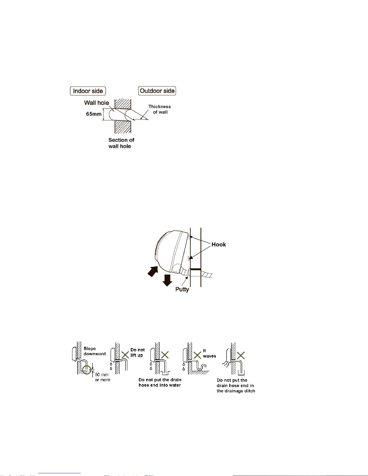
B.1.4. Drilling the Condensate Drainage Hole
1. Ensure that the hole for condensate drainage is correctly positioned. The height should be lower than the bottom
edge of the indoor unit.
2. Drill a 65mm diameter hole with a descending slope.
3. Seal it off with putty after installation.
B.1.5. Installing the Hydronic Unit
1. Pass the piping through the hole in the wall and hook the indoor unit on the mounting plate by the upper hooks.
2. Move the body of the unit from side to verify if it is securely fixed.
3. While pushing the unit toward the wall, lift it slightly from beneath to hook it up on the mounting plate by the
lower hooks.
4. Make sure the unit firmly rests on the hooks of the mounting plate.
B.1.6. Drainage Piping Works
1. Install the drain hose so that it slopes downward slightly for free drainage. Avoid installing it as shown in the below
illustrations marked with an “X”.
2. Put water in the drain pan and make sure that the water drains outdoors.
3. If the flexible drain hose provided with the indoor unit is not long enough, please extend it by joining it to an
extension hose (not provided). Be sure to insulate the connecting part of the extension drain hose with a shield
pipe as shown.
Page 10 of 36
AER.MIU.HWNEC.GB.01.04/14 SK2014-SON-002-TechMnl-SWC-001
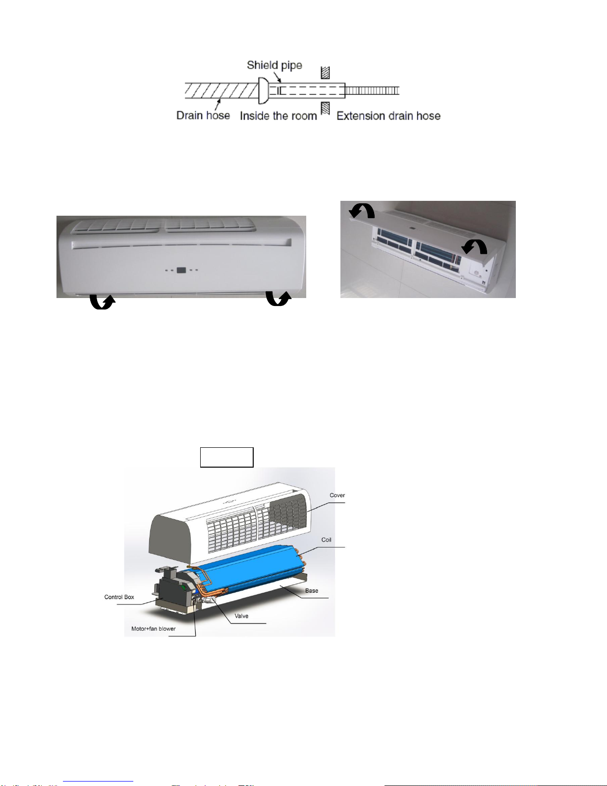
Open the grille cover by lifting from the
bottom position indicated by the arrows
4. If the attached drain hose passes through an indoor area, insulate it with heat insulation material.
B.2. Unit Maintenances and Preparations
B.2.1. Opening and Closing Of Lift-Up Grille Cover
B.2.2. Removing Front Cover Assembly
1. Set the horizontal louver to the horizontal position.
2. Remove the screw caps below the louver, and then remove the mounting screws.
3. Open the lift-up grille cover by grasping the panel at both sides as shown above.
4. Remove the remaining screws located in the center of the unit/of the front cover.
5. Grasp the lower part of the front cover and pull the entire assembly out and up towards you.
Close the grille cover by pressing down at the
positions indicated by the arrows.
HWN

Page 11 of 36
AER.MIU.HWNEC.GB.01.04/14 SK2014-SON-002-TechMnl-SWC-001
B.2.3. Air Purging
1. After connecting the water inlet and outlet pipes to the main supply lines turn on the main breaker and operate the
unit in COOLING mode.
2. Open the water inlet valve and flood the coil.
3. Check all connections for water leakage. If no leak is found open the water purge/air vent valve with an open end
wrench and support the unit by hand. Then purge the air trapped inside the coil. When performing this activity,
take care not to touch the electrical parts.
4. Close the water purge/air vent valve when no bubbles appear.
5. Open the water outlet valve.
B.2.4. Wiring Connections
Unit components are wired to the terminal block of the indoor unit. Wiring can be accessed from the terminal block
inside the control box.
B.3. Pipe Connections with Valve
Complete Assembly
C. Control Specifications
C.1. EBWPCGH –EC Complete function FCU Controller
Used in all High-Wall [V/P] ~S unit configurations.
Complete function integrated controller, compatible with IR handset controller, wired wall-pad, serial networking for
master-slave and MODBUS applications.
C.1.1. Abbreviations
Ts = Setting temperature
Tr = Room air temperature
Ti1 = Chilled water coil temperature
Ti2 = Hot water coil temperature
AUX1 = Hot water free contact
AUX2 = Chilled water free contact
MTV1 = Chilled Motorized valve
MTV2 = Hot Motorized valve
C.1.2. Definition of Input/Output

Page 12 of 36
AER.MIU.HWNEC.GB.01.04/14 SK2014-SON-002-TechMnl-SWC-001
I/O
Code
2-Pipe
4-Pipe
Analogue Input
Return air sensor
AI1
Return air temperature (Tr)
2-pipe coil circuit sensor
AI2
Chilled / hot water coil
circuit (Ti1)
Chilled water coil circuit
(Ti1)
Hot water sensor
AI3
N/A
Hot water coil circuit
(Ti2)
Input
LED display / IR receiver
X-DIS1
Digital communication port to LED display / IR receiver
board.
Wired wall pad
TTL1
Digital communication port to wired wall pad board.
Digital input
Occupancy contact
On/Off
Window contacts:
For remote ON/OFF (when DIPB SW1 = 1).
Economy contacts:
For remote activation of economy mode (when DIPB
SW1 = 0).
Electrical heater safety switch
EH
Voltage-free (NC). The contact is closed before the EH is
turned on.
Power input
Phase
L1
Power supply to the PCB and all the loads connected to
the voltage outputs. Max length: 5 m.
Neutral
N1
Power supply to the PCB and all the loads connected to
the voltage outputs. Max length: 5 m.
Earth
PE1
Power supply to the PCB and all the loads connected to
the voltage outputs. Max length: 5 m.
Voltage output
Fan
CN4
Fan driver
Valve 1
MTV1
2-pipe coil circuit valve
output –chilled / hot water
valve.
Voltage output (L)
4-pipe coil circuit valve
output –chilled water
valve.
Voltage output (L)
Valve 2
MTV2
Reserved
4-pipe coil circuit valve
output –hot water valve.
Voltage output (L)
Voltage of electrical heater
(Live)
HEAT
Voltage output (L), maximum 25 A
Output
Stepping motor
CN1 / CN2
Louver stepping motor relay
Auxiliary contact 2
AUX2
Cooling mode signal relay (NO). Voltage free contact.
To ensure the sensitivity of the connection, please
make sure max wiring length < 5 m, 5 A
Auxiliary contact 1
AUX1
Heating mode signal switch (NO). Voltage free contact.
To ensure the sensitivity of the connection, please
make sure max wiring length < 5 m. 5 A
Serial BUS port
CN3
Master-slave network serial connection OR
MODBUS / local PC host network serial connection.
Page 13 of 36
SK2014-SON-002-TechMnl-SWC-003
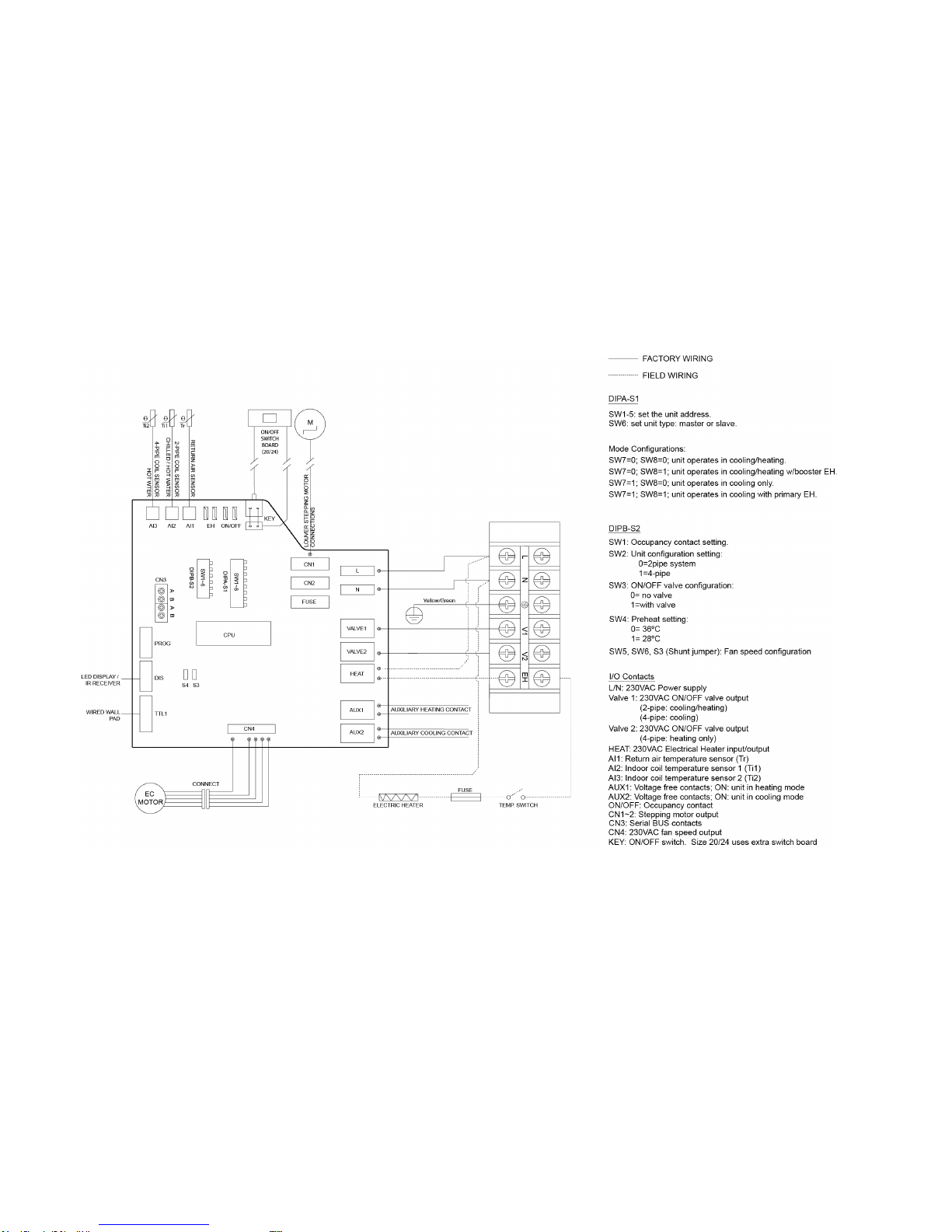
C.1.3. Wiring Diagram EBWPCGH-EC
Page 14 of 36
SK2014-SON-002-TechMnl-SWC-003
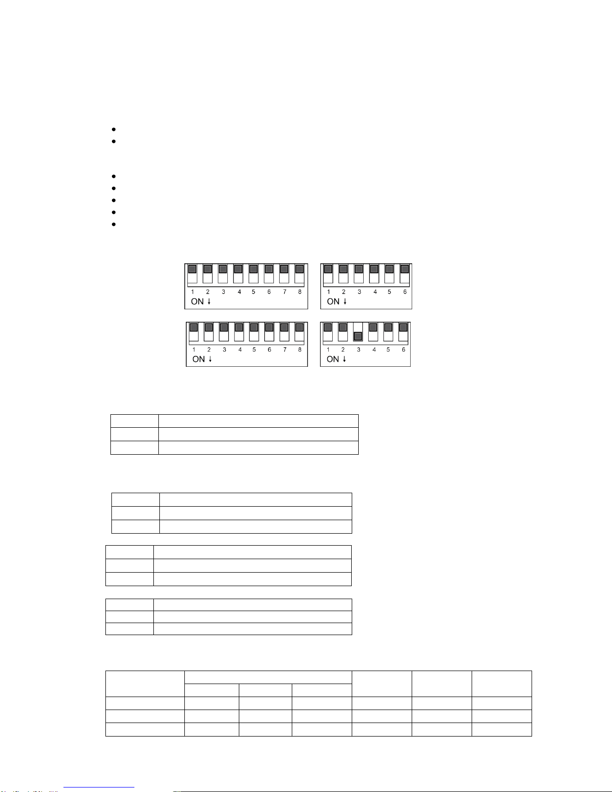
C.1.4. Configuration Settings
There are 2 DIP switches set on the PCB:
a) DIPA-S1 (8 positions)
SW1 –SW6: used for master-slave / BMS network address.
SW7 –SW8: used for operating mode configuration.
b) DIPB-S2 (6 positions)
SW1: Occupancy / economy mode selection.
SW2: 2-pipe / 4-pipe configuration selection.
SW3: Thermoelectric valve configuration selection (2-pipe system only).
SW4: Pre-heat protection temperature selection.
SW5 –SW6: brushless DC fan motor configuration.
1. Default DIP Switch Settings:
DIPA –S1 DIPB –S2
2. Thermoelectric Valve Configuration:
On board DIP switch SW3 of DIPB is used for this configuration.
3. Unit Configuration:
On board DIP Switches of DIPB are used for the below configurations.
SW1
PR-O contact setting
0
Economy contact
1
Window contact
SW2
System setting
0
2-pipes system
1
4-pipes system
SW4
Preheat setting
1
28°C
0
36°C
4. Motorized Fan Speed Settings for Different Models:
Unit Model
Speed (RPM)
S3
SW5
SW6
Low
Medium
High
HWN-2-EC -25
600
700
930
0
0
1
HWN-2-EC -30
700
800
1150
0
1
1
HWN-2-EC-40
900
1100
1300
1
0
0
SW3
Thermoelectric valve (MTV)
1
With valve
0
No valve
Unit Configuration
WITHOUT Valve
Unit Configuration
WITH Valve
0=OFF
1=ON

Page 15 of 36
SK2014-SON-002-TechMnl-SWC-003
5. Mode configuration:
DIPA-S1
Model
SW7
SW8
Model setting
0
0
Cool-Heat
0
1
Cool-Heat + booster heater
1
0
Cooling only
1
1
Cool + primary heater
6. Unit ON/OFF
There are 3 ways to turn the system on or off:
a) By the ON/OFF button on the handset or wired wall pad.
b) By the programmable timer on the handset or wired wall pad.
c) By the manual control button on the air conditioner.
7. Auto-Restart
The system uses a non-volatile memory to save the present operation parameters when system is turned off or in
case of system failure or cessation of power supply.
The restored parameter data-set depends on the type of user interface.
a) Handset only user interface:
When the power on signal is received by the air conditioner and no wired wall-pad is installed, the Mode,
Fan Speed, Set temperature and Louver/Swing setting will be the same as the handset setting before the
last power off.
b) Wall-pad only OR wall-pad and handset user interface:
When the power on signal is received by the air conditioner and a wired wall-pad is installed, the Mode,
Fan Speed, Set temperature, Louver/Swing setting and Timer ON/OFF weekly program will be the same as
the wall pad setting before the last power off.
C.1.5. Control Logics for 2-Pipe System
C.1.5.1. With Thermoelectric Valve Configuration
COOL MODE
a) MTV2, AUX1 and electric heater are always off.
b) If Tr ≥ Ts + 1ºC (or + 4ºC if economy contact is activated), then cool operation is activated and MTV1 and
AUX2 are turned on. Indoor fan runs at set speed.
c) If Tr < Ts, then cool operation is terminated and MTV1 and AUX2 are turned off. Indoor fan runs at set
speed.
d) The range of Ts is 16 - 30ºC
e) Indoor fan speed can be adjusted to low, medium, high and auto.
f) When turned on, MTV1 requires 30 seconds before it is fully open.
g) When turned off, MTV1 requires 120 seconds before it is fully closed.
h) When the unit is turned off, the indoor fan will shut down after 5 seconds.
LOW TEMPERATURE PROTECTION OF INDOOR COIL
a) If Ti1 ≤ 2 ºC for 2 minutes, then MTV1 and AUX2 are turned off. If indoor fan is set for low speed, then it
will run at medium speed. If it is set at medium or high speed, then it will keep running at the same
speed.
b) If Ti1 ≥ 5ºC for 2 minutes, then MTV1 and AUX2 are turned on. Indoor fan runs at set speed.
FAN MODE
a) Indoor fan runs at the set speed while heater, MTV1, MTV2, AUX1 and AUX2 are turned off.
b) Indoor fan speed can be adjusted to low, medium and high.
HEAT MODE
Without Electrical Heater

Page 16 of 36
SK2014-SON-002-TechMnl-SWC-003
a) MTV2, AUX2 and electric heater are always off.
b) If Tr ≤ Ts - 1 ºC (or - 4ºC if economy contact is activated), then heat operation is activated and MTV1 and
AUX1 are turned on. Indoor fan runs at the set speed.
c) If Tr > Ts, then heat operation is terminated and MTV1 and AUX1 are turned off. Indoor fan runs at
200rpm.
d) The range of Ts is 16 - 30ºC.
e) Indoor fan speed can be adjusted to low, medium, high and auto.
f) When turned on, MTV1 requires 30 seconds before it is fully open.
g) When turned off, MTV1 requires 120 seconds before it is fully closed.
PRE-HEAT
a) If Ti1 < 36ºC [or < 28ºC is selected by DIPB-S2 position SW4], then MTV1 and AUX1 are turned
on, indoor fan runs at 200rpm.
b) If Ti1 ≥ 38ºC [or ≥ 30ºC is selected by DIPB-S2 position SW4], then MTV1 and AUX1 are turned
on, indoor fan runs at set speed.
c) If the indoor coil temperature sensor is damaged, then the pre-heat time is set for 2 minutes.
Indoor fan runs at set speed.
POST-HEAT
a) If Ti1 ≥ 38ºC, then MTV1 and AUX 1 are off, then indoor fan continues to run at set speed.
b) If 36ºC ≤ Ti1 ≤ 38ºC, then MTV1 and AUX1 are turned off. Then indoor fan maintains its original state.
c) If Ti1 < 36ºC, then MTV1 and AUX1 are turned off. Then indoor fan runs at 200rpm.
d) If the indoor coil temperature sensor is damaged, then the post-heat time is set for 3 minutes. Indoor
fan runs at set speed.
DEHUMIDIFICATION MODE
a) MTV2, AUX1 and heater are always off.
b) If Tr ≥ 25ºC, then MTV1 and AUX2 will be ON for 3 minutes, and then OFF for 4 minutes.
c) If 16ºC ≤ Tr < 25ºC, then MTV1 and AUX2 will be ON for 3 minutes, and then OFF for 6 minutes.
d) If Tr < 16ºC, then MTV1 and AUX2 will be turned off for 4 minutes.
e) At the end of the above dehumidification cycle, the system will decide the next dehumidification
control option. Indoor fan will run at low speed throughout the dehumidification process.
AUTOMODE
a) Every time the unit is turned on, MTV1 is on while AUX1, AUX2 and fan are off. MTV2
and the heater are always off. After 120 seconds, the subsequent operation mode is
decided according to the following:
1) If the coil temperature sensor (Ti1) ≥ 36°C, then MTV1, AUX1 and fan turn on or
off according to HEAT mode.
2) If Ti1 < 36°C, then MTV1, AUX2 and fan turn on or off according to COOL mode.
b) Unit remains in AUTO COOL or AUTO HEAT mode throughout the operating cycle until
the user changes the mode manually or restarts the unit.
c) Should the Ti1 sensor fail or be damaged, auto mode will not function.
Note: AUTO COOL or AUTO HEAT operations are the same as COOL or HEAT mode
respectively.
C.1.5.2. Without Thermoelectric Valve Configuration
COOL MODE
a) Heater, AUX1, MTV1 and MTV2 are always off.
b) If Tr ≥ Ts + 1ºC (or + 4ºC if economy contact is activated), then cool operation is activated and AUX2
is turned on. Indoor fan runs at set speed.
c) If Tr < Ts, then cool operation is terminated and AUX2 is off. Indoor fan is turned off.
d) The range of Ts is 16 - 30ºC.
e) Indoor fan speed can be adjusted to low, medium, high and auto.

Page 17 of 36
SK2014-SON-002-TechMnl-SWC-003
f) When the unit is turned off, indoor fan shut down after 5 seconds.
LOW TEMPERATURE PROTECTION OF INDOOR COIL
a) If Ti1 ≤ 2ºC for 2 minutes, AUX2 is turned off. If low speed is selected via user interface, indoor fan runs at
medium speed. If medium or high speed is selected via user interface, indoor fan runs at set speed.
b) If Ti1 ≥ 5ºC for 2 minutes, AUX2 is turned on. Indoor fan runs at set speed.
FAN MODE
a) Indoor fan runs at the set speed while heater, AUX1, AUX2, MTV1 and MTV2 are turned off.
b) Indoor fan speed can be adjusted to low, medium and high.
HEAT MODE
a) MTV1, MTV2, AUX2 and heater are always off.
b) If Tr ≤ Ts - 1ºC (or - 4ºC if economy contact is activated), then heat operation is activated and AUX1
is turned on. Indoor fan runs at the set speed.
c) If Tr > Ts, then heat operation is terminated and AUX1 is turned off. Indoor fan runs at 200rpm.
d) The range of Ts is 16 - 30ºC.
e) Indoor fan speed can be adjusted to low, medium, high and auto.
PRE-HEAT
Without Electrical Heater
a) MTV1, MTV2 and AUX2 are off.
b) If Ti1 < 36ºC (or > 28ºC is selected by DIPB-S2 position SW4), then AUX1 is turned on
while indoor fan remains off.
c) If Ti1 ≥38ºC (or < 30ºC is selected by DIPB-S2 position SW4), then AUX1 is turned on
while indoor fan runs at set speed.
d) If the indoor coil temperature sensor is damaged, then the pre-heat time is set for 2
minutes and the indoor fan runs at set speed.
POST-HEAT
a) AUX1 is turned off. Electrical heater is turned off.
b) Indoor fan will shut down after the unit has been turned off for 20 seconds.
LOW TEMPERATURE PROTECTION OF INDOOR COIL
a) If Ti1 ≤ 2ºC for 2 minutes, then AUX2 is turned off. If indoor fan runs at low speed, then it will run
at medium speed. If indoor fan runs at medium or high speed, then it will run at set speed.
b) If Ti1 ≥ 5ºC for 2 minutes, then AUX2 is turned on. Indoor fan runs at set speed.
OVER-HEAT PROTECTION OF INDOOR COIL
a) If Ti1 ≥ 75ºC, then AUX1 is turned off. Indoor fan remains on and runs at high speed.
b) If Ti1 < 70ºC, then AUX1 is turned on. Indoor fan remains and runs at set speed.
c) If the indoor coil temperature sensor is damaged, then the protection mode will be
overridden and the unit will work according to the pre-heat and post-heat program.
DEHUMIDIFICATION MODE
a) MTV1, MTV2, AUX1 and heater are always off.
b) If Tr ≥ 25ºC, then the indoor fan and AUX2 will be turned on for 3 minutes, and then off
for 4 minutes.
c) If 16ºC ≤Tr < 25ºC, then the indoor fan and AUX2 will be turned on for 3 minutes, and
then off for 6 minutes.
d) If Tr < 16ºC, then the indoor fan and AUX2 will be turned off for 4 minutes.
e) At the end of the above dehumidification cycle, the system will decide the next
dehumidification control option. Indoor fan will run at low speed throughout the
dehumidification process.
AUTO-MODE
Not allowed.
C.1.6. Control Logics for 4-Pipe System
Note: 4-pipe system must always be equipped with 2 valves.
COOL MODE
a) MTV2, AUX1 and Electrical Heater are always off.

Page 18 of 36
SK2014-SON-002-TechMnl-SWC-003
b) If Tr ≥ Ts + 1ºC (or + 4ºC if economy contact is activated), then cool operation is activated, MTV1 and AUX2 are
turned on. Indoor fan runs at set speed.
c) If Tr < Ts, then cool operation is terminated, MTV1 and AUX2 are turned off. Indoor fan runs at set speed.
d) The range of Ts is 16 - 30ºC
e) Indoor fan speed can be adjusted to low, medium, high and auto.
f) When turned on, MTV1 requires 30 seconds before it is fully open.
g) When turned off, MTV1 requires 120 seconds before it is fully closed.
h) When the unit is turned off, the indoor fan will shut down after 5 seconds.
FAN MODE
a) Indoor fan runs at the set speed while heater, MTV1, MTV2, AUX1 and AUX2 are turned off.
b) Indoor fan speed can be adjusted to low, medium and high.
HEAT MODE
a) MTV1, AUX2 and electric heater are always off.
b) If Tr ≤ Ts - 1ºC (or - 4ºC if economy contact is activated), then heat operation is activated
and MTV2 and AUX1 are turned on. Indoor fan runs at the set speed.
c) If Tr > Ts, then heat operation is terminated and MTV2 and AUX1 are turned off. Indoor fan
runs at 200RPM.
d) The range of Ts is 16 - 30ºC.
e) Indoor fan speed can be adjusted to low, medium, high and auto.
f) When turned on, MTV2 requires 30 seconds before it is fully open.
g) When turned off, MTV2 requires120 seconds before it is fully closed.
PRE-HEAT
a) If Ti1 < 36ºC [or 28ºC depending on DIP setting], then MTV2 and AUX1 are turned on. Indoor
fan runs at 200RPM.
b) If Ti1 ≥38ºC [or 30ºC depending on DIP setting], then MTV2 and AUX1 are turned on. Indoor
fan runs at set speed.
c) If indoor coil temperature sensor is damaged, then the pre-heat time is set for 2 minutes.
Indoor fan runs at set speed.
POST-HEAT
a) If Ti2 ≥38ºC, then MTV2 and AUX 1 are turned off. Indoor fan continues to run at set speed.
b) If 36 F ≤ Ti2 ≤38 F, then MTV2 and AUX1 are turned off. Indoor fan maintain its original
state.
c) If Ti2 < 36ºC, then MTV2 and AUX1 are turned off. Indoor fan repeatedly runs for 30 seconds
and then stops for 3 minutes.
d) If the indoor coil temperature sensor is damaged, then the post-heat time is set for 3
minutes. Indoor fan running at set speed.
LOW TEMPERATURE PROTECTION OF INDOOR COIL
a) If Ti1 ≤ 2ºC for 2 minutes, then MTV1 and AUX2 are turned off. If indoor fan is set for low speed, then it
will run at medium speed. If it is set at medium or high speed, then it will keep running at the same
speed.
b) If Ti1 ≥ 5ºC for 2 minutes, then MTV1 and AUX2 are turned on. Indoor fan runs at set speed.
OVER HEAT PROTECTION OF INDOOR COIL
a) If Ti2 ≥ 75ºC, then MTV2 and AUX1 are turned off. Indoor fan remains on and runs at high speed.
b) If Ti2 < 70ºC, then MTV2 and AUX1 are turned on. Indoor fan remains on and runs at set speed.
c) If the indoor coil temperature sensor is damaged, then the protection mode will be overridden and the
unit will work according to the pre-heat and post-heat set times.
DEHUMIDIFICATION MODE

Page 19 of 36
SK2014-SON-002-TechMnl-SWC-003
a) MTV2, AUX1 and heater are always off.
b) If Tr ≥ 25ºC, then MTV1 and AUX2 will be turned on for 3 minutes, and then off for 4 minutes.
c) If 16ºC ≤Tr < 25ºC, then MTV1 and AUX2 will be turned on for 3 minutes, and then off for 6 minutes.
d) If Tr <16ºC, then MTV1 and AUX2 will be turned off for 4 minutes.
At the end of the above dehumidification cycle, the system will decide the next dehumidification control option.
Indoor fan will run at low speed throughout the dehumidification process.
AUTO-MODE
a) If the current running mode is AUTO COOL mode, it will change over to AUTO HEAT mode upon satisfying all
the conditions below:
1) Ts –Tr ≥1°C (or –4ºC if economy contact is activated).
2) MTV1 has stopped ≥10 minutes.
b) If the current running mode is AUTO HEAT mode, it will change over to AUTO COOL mode upon satisfying all
the conditions below:
1) Tr - Ts ≥1°C (or + 4ºC if economy contact is activated).
2) MTV2 has stopped ≥10 minutes.
Note: AUTO COOL or AUTO HEAT operations are the same as COOL or HEAT mode respectively.
SLEEP MODE
a) SLEEP mode can only be set when the unit is in COOL or HEAT mode.
b) In COOL mode, after SLEEP mode is set, the indoor fan will run at low speed and Ts will increase by 2ºC over 2
hours.
c) In HEAT mode, after SLEEP mode is set, the indoor fan will run at set speed and Ts will decrease by
2ºC over 2 hours.
d) Changing of operation mode will cancel SLEEP mode.
C.1.7. Auto Fan Speed
a) In COOL mode, the fan speed cannot change until it has run for more than 30 seconds.
b) In HEAT mode, the fan speed cannot change until it has run for more than 30 seconds.
C.1.8. Louver
For remote handset
Whenever the indoor fan is running, the louver can swing or stop at the desired position.
Louver angle: 0~100º, opens clockwise with widest angle at 100º.
Swing angle: 35~100º, opens clockwise to 68º. Below are the 4 fixed positions which can be set from wireless
LCD handset.
Position
Angle
1
35º
2
57º
3
83º
4
100º
For wired wall pad
Louver angle: 0~100º, opens clockwise with angle at 100º.
Swing angle: 35~100º, opens clockwise to 68º. User may stop louver at any desired position between 35~100º.
C.1.9. Buzzer
If a command is received by the air conditioner, the master unit will respond with 2 beeps for each setting,
while the slave unit will respond with 1 beep.
C.1.10. Auto Restart

Page 20 of 36
SK2014-SON-002-TechMnl-SWC-003
The system uses non-volatile memory to save the present operation parameters when system is turned off or
in case of system failure or cessation of power supply. Operation parameters when using a handset are Mode,
Set Temperature, Swing, and Fan Speed. When using a wall pad the parameters are Mode, Set Temperature,
Swing, and Fan Speed, as well as the 7-day ON/OFF Timer program. When power supply resumes or the system
is switched on again, the same operations as previously set will function.
C.1.11. Operation Of Control Panel On High-Wall Unit
C.1.11.1. On/Off Switch
a) This is a tactile switch to select Cool→Heat→Off operation mode.
b) In COOL mode, the set temperature of the system is 24ºC with auto fan speed and swing. There are no timer
and sleep modes.
c) In HEAT mode, the set temperature of the system is 24ºC with auto fan speed and swing. There are no timer
and sleep modes.
d) Master unit that does not use a wall pad will globally broadcast.
Note: When button pressing is effective, the master unit buzzer will beep twice and the slave unit will beep once.
This manual suits for next models
1
Table of contents
Other Aertesi Air Conditioner manuals


Popular Air Conditioner manuals by other brands


Mitsubishi Electric
Mitsubishi Electric PLH-P1.6KAH installation manual

GREE ELECTRIC
GREE ELECTRIC MULTI18HP230V1BO Service manual

Airxcel
Airxcel 48000 Series Operation and maintenance instructions

SCE
SCE Enviro-Therm SCE-AC8500B460V user manual

Fujitsu
Fujitsu ARXG54KHTA Design & technical manual

LG
LG W051CE SSP owner's manual


