Aertesi SOFFIO User manual

AERTESI srl SOFFIO –Technical manual
Page 1 AER.MT.GB.SOF.001.05.15
TECHNICAL MANUAL
SOFFIO
Ducted units

AERTESI srl SOFFIO –Technical manual
Page 2 AER.MT.GB.SOF.001.05.15
INDEX
1-INTRODUCTION............................................................................................................................................ 4
2-OPERATING LIMITS...................................................................................................................................... 4
3- KEY TO READING CODES.......................................................................................................................... 5
4-TECHNICAL SPECS...................................................................................................................................... 6
5-TECHNICAL DATA (AC motors).................................................................................................................... 7
5.1-Unit 2 pipes with 3 row coil ...................................................................................................................... 7
5.2-Unit 4 pipes with 3 row coil + 1 row auxiliary coil..................................................................................... 8
6-TECHNICAL DATA OF OPTIONAL COILS (AC motors)............................................................................... 9
6.1-Optional main coils................................................................................................................................... 9
6.2-Optional auxiliary coils............................................................................................................................. 9
6.3-Direct expansion coils............................................................................................................................ 10
6.4-Coils for “district-cooling” ....................................................................................................................... 10
9- DIMENSIONS AND WEIGHTS................................................................................................................... 11
9.1-Dimensions and weights for horizontal version ..................................................................................... 11
9.2- Dimensions and weights for vertical version VC .................................................................................. 13
9.3-Dimensions and weights for vertical version VD ................................................................................... 15
9.4-Hydraulic connections and volume of coils............................................................................................ 17
10-ACCESSORIES.......................................................................................................................................... 17
10.1-Valves .................................................................................................................................................. 20
10.2-Condensation drainage pump.............................................................................................................. 23
10.3-Electric heater...................................................................................................................................... 23
10.4-Flat flange (FP).................................................................................................................................... 24
10.5-Inlet flange (FRA)................................................................................................................................. 24
10.6-Inlet flange (FRAL)............................................................................................................................... 25
10.7-Inlet flange for vertical version (FRAV)................................................................................................ 26
10.8-Outlet grill (GM2) and inlet grill (GR) ................................................................................................... 26
10.9-Decorative inlet grill (GRD).................................................................................................................. 27
10.10-Plenum 90° (P90) .............................................................................................................................. 27
10.11-External air mixture suction plenum (PMA) ....................................................................................... 28
10.12-Straight Plenum (PD)......................................................................................................................... 29
10.13-Plenum with outlet grill (PGM2)......................................................................................................... 29

AERTESI srl SOFFIO –Technical manual
Page 3 AER.MT.GB.SOF.001.05.15
10.14-Plenum with inlet grill (PGR).............................................................................................................. 30
10.15-Plenum with spigot (PS) .................................................................................................................... 31
10.16-Plenum for air regulation (PRA)......................................................................................................... 31
10.17-Plenum with post-heating coil with 3 or 4 rows (PB3 –PB4) ............................................................ 32
10.18-Silenced plenum (SL) ........................................................................................................................ 33
10.19-Free air application unit (BL).............................................................................................................. 34
10.20-Bag filter plenum (FRAF6 , FRAF7, FRAF8)..................................................................................... 34
11-Electrical connections................................................................................................................................. 36
AERTESI srl SOFFIO –Technical manual
Page 4 AER.MT.GB.SOF.001.05.15
1-INTRODUCTION
The SOFFIO Series is designed for the air-conditioning systems in residential and commercial application,
for indoor installations, not to expose to low or high extreme temperatures, dust-free and non-explosive
environment. The manufacturer is not responsible in case of incorrect use.
The units are designed to be ducted. To install without ducts can produce malfunctioning or damage of the
unit.
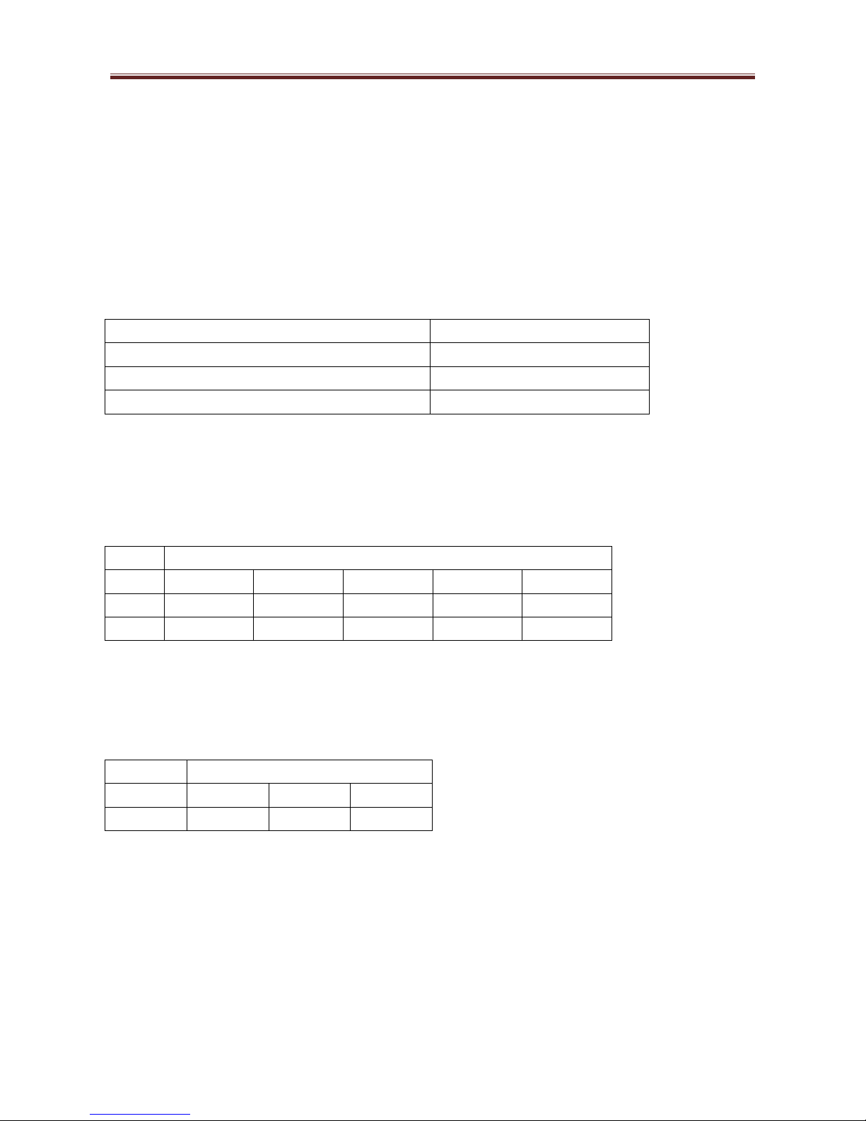
2-OPERATING LIMITS
Power supply
230÷240V/50Hz –240V/60Hz (1)
Inlet water temperature
3 ÷ 90°C
Maximum temperature air outlet (2)
50°C
Temperature of air inlet
10÷ 50°C
(1) +/-6% of margin on the voltage. All the technical data given in this manual refer to 230V / 50Hz.
(2) In case of water with outlet temperature higher than 50°C, please verify the temperature of the air outlet
with selection software TESI10
Minimal counter pressure (motor range)
21
31
38
41
81
50Hz
0Pa
0 Pa
0 Pa
0 Pa
0 Pa
60Hz
0 Pa
0 Pa
0 Pa
40 Pa
0 Pa
The working with low external counter pressure, even if inside the motor range, may cause the separation of
drops from the coil during summer operation (to be evaluated also according to the degree of humidity). To
avoid this possibility, you should work with at least 40Pa of pressure and not more of the following air flow:
Maximum air flow
MODEL
21
31-38
41-81
CAPACITY
1250 mc/h
2300 mc/h
4500 mc/h
We suggest to let the unit work to the extremes of these operating limits only for short periods, because the
operation for a long period of time may reduce the normal duration of the components.

AERTESI srl SOFFIO –Technical manual
Page 5 AER.MT.GB.SOF.001.05.15
3- KEY TO READING CODES
The standard version is horizontal, single panel, 3 row coils, three-speed AC motor, right hydraulic
connections. All other versions are optional.

AERTESI srl SOFFIO –Technical manual
Page 6 AER.MT.GB.SOF.001.05.15
4-TECHNICAL SPECS
STRUCTURE: made of galvanized steel, thickness 1.00 ÷ 1, 50 mm. The sturdy structure prevents vibrations
and includes the mounting brackets to the ceiling. On request, it can be painted.
ACCESSIBILITY: the filter can be removed both from the bottom and the sides, without the aid of tools (if
some accessories are installed on the suction side, please refer to the specific chapter of this manual for
more information). Accessibility to internal components is guaranteed by removing the bottom panel. The
plate of the fan deck can be removed without disconnecting the ducts and the operation can take place from
below, without the need to intervene on the sides or front of the unit.
FILTER: class G3 (EN779), thickness 15 mm, synthetic fiber. Other types upon request.
FAN DECK (AC motors): the fans are forward curved blades, double suction centrifugal fan, directly coupled
to the motor. The cochlea is made of galvanized steel, the fan in aluminum. The motor and the fans are
balanced on the plate of the fan deck after their assembly. The motor is mounted on rubber anti-vibration
supports , protection level IP20, 3 speeds.
FAN DECK (EC motors): the fans have forward curved blades, double suction centrifugal fan, directly
coupled to the motor. The cochlea is made of galvanized steel, the fan in aluminum (size 21-31) or in plastic
(size 38-41-81). The motor and the fans are balanced on the plate of the fan deck after their assembly. The
motor is mounted on rubber anti-vibration supports, protection level IP20, control signal 0-10V.
COIL: made with copper tube 3/8" diameter and corrugated aluminum fins with high efficiency, with manual
air purge valve at the top of the collector. The standard connections are right (looking in front of the air flow).
Left on request. Nominal pressure PN10.
The direct expansion coils (optional) are made with copper tube 5/16 "diameter and they are suitable to work
with refrigerant R410A (up to 45bar). Other refrigerants on request.
CONDENSATION DRAIN PAN: made of galvanized steel and painted to prevent rust. The drainage pipe and
the edges are welded to avoid losses even after a long time. The drain pan is externally insulated with
thermal insulation and it is mounted with slope towards the drain pipe to avoid water stagnations.
INSULATION: made of polyurethane with thickness 10 mm, HF1 class according to the rule UL94 (flame
retardant and not dripping). The thermo-acoustic insulation is protected against moisture and dust thanks to
a surface film.
ELECTRICAL PANEL: made in galvanized steel or plastic, it is positioned on the opposite side to hydraulic
connections. On request it can be made with a watertight box in plastic and it can be placed on the same
side of the hydraulic connections.

AERTESI srl SOFFIO –Technical manual
Page 7 AER.MT.GB.SOF.001.05.15
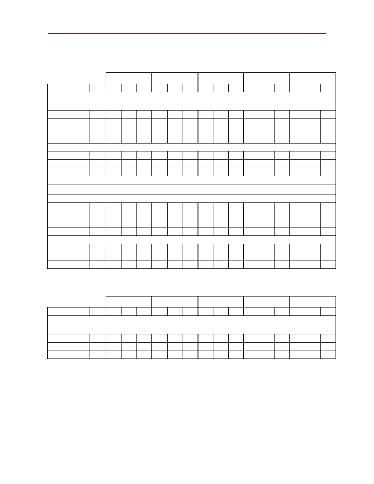
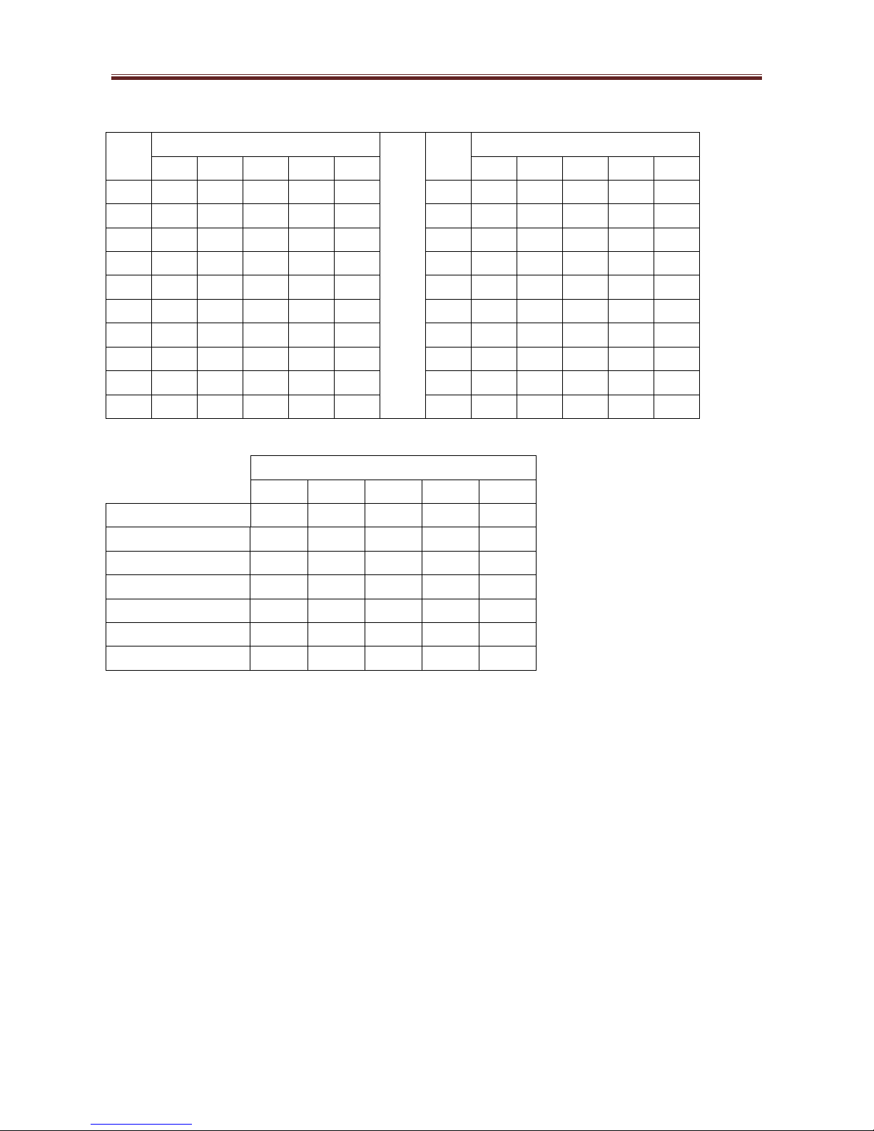
5-TECHNICAL DATA (AC motors)
5.1-Unit 2 pipes with 3 row coil
EUROVENT
certification not
needed (*)
21
31
38
41
81
Speed (E)
min
med
max
min
med
max
min
med
max
min
med
max
min
med
max
Air flow (E)
mc/h
508
752
880
1374
1555
1630
1619
1854
2009
2326
2722
3071
2980
3516
4037
Pressure (E)
Pa
23
50
68
40
50
56
38
50
59
37
50
64
35
50
67
COOLING –air 27°C b.s. , 19°C b.u. –water inlet 7°C , outlet 12°C
Total rating (E)
kW
2.74
3.63
4.06
6.78
7.38
7.62
7.6
8.31
8.76
12.05
13.42
14.62
14.27
16.06
17.62
Sensible rating (E)
kW
1.96
2.59
2.87
4.74
5.16
5.32
5.29
5.8
6.14
8.45
9.4
10.21
9.97
11.09
12.25
Water flow
l/h
470
623
697
1163
1266
1307
1303
1425
1503
2067
2302
2509
2449
2756
3024
Δp water (E)
kPa
8
13.5
16.6
14.4
16.8
17.8
17.7
20.9
23.1
11.2
13.7
16
15.3
19
22.5
HEATING –air 20°C –water inlet 50°C , same water flow of cooling
Rating (E)
kW
3.6
4.83
5.41
8.91
9.75
10.06
10.02
10.8
11.65
15.74
17.65
19.28
18.85
21.22
23.38
Water flow
l/h
470
623
697
1163
1266
1307
1303
1397
1503
2067
2302
2509
2449
2756
3024
Δp water (E)
kPa
6.9
11.7
14.4
12.3
14.3
15.2
15.1
17.2
19.7
9.5
11.5
13.5
12.9
16
19
ELECTRICAL POWER CONSUMPTION
Power
consumption (E)
W
70
129
150
168
191
225
233
258
303
402
486
549
620
814
914
Max current
A
0.8
1.3
1.6
2.5
4.5
SOUND DATA
Sound power
suction+radial (E)
dB(A)
51
60
65
64
68
69
65
67
70
65
68
70
70
74
77
Sound power outlet
(E)
dB(A)
50
59
64
63
67
68
64
66
69
64
67
69
69
73
76
Sound pressure
suction+radial
dB(A)
42
51
56
55
59
60
56
58
61
56
59
61
61
65
68
Sound pressure
outlet
dB(A)
41
50
55
54
58
59
55
57
60
55
58
60
60
64
67
(E)= performances EUROVENT certified
(*)= size 81 has no need to be EUROVENT certified

AERTESI srl SOFFIO –Technical manual
Page 8 AER.MT.GB.SOF.001.05.15
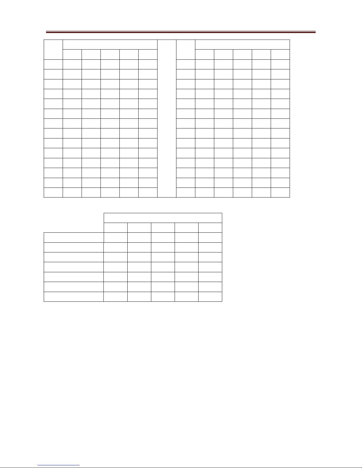
5.2-Unit 4 pipes with 3 row coil + 1 row auxiliary coil
EUROVENT
certification not
needed (*)
21
31
38
41
81
Speed (E)
min
med
max
min
med
max
min
med
max
min
med
max
min
med
max
Air flow (E)
mc/h
500
734
856
1344
1506
1582
1573
1798
1939
2312
2695
3033
2946
3453
3989
Pressure (E)
Pa
23
50
67
40
50
55
38
50
58
37
50
64
36
50
67
COOLING –air 27°C b.s. , 19°C b.u. –water inlet 7°C , outlet 12°C
Total rating (E)
kW
2.7
3.58
3.99
6.68
7.2
7.47
7.45
8.14
8.59
11.97
13.34
14.52
14.23
15.85
17.38
Sensible rating (E)
kW
1.94
2.54
2.8
4.66
5.02
5.2
5.19
5.66
5.96
8.4
9.32
10.11
9.85
11.01
12.19
Water flow
l/h
463
614
684
1146
1236
1282
1278
1397
1474
2054
2289
2491
2441
2720
2982
Δp water (E)
kPa
7.8
13.1
16
14
16.1
17.2
17.1
20.2
22.2
11.1
13.5
15.8
15.2
18.5
21.9
HEATING - air 20°C - water inlet 70°C , outlet 60°C
Rating (E)
kW
2.99
3.81
4.22
7.06
7.62
7.8
7.76
8.4
8.81
13.05
14.34
15.35
15.1
16.58
17.99
Water flow
l/h
262
335
371
620
669
685
681
738
774
1146
1260
1348
1326
1456
1580
Δp water (E)
kPa
2.6
4.1
4.9
5.6
6.5
6.8
6.7
7.8
8.5
6.5
7.8
8.9
8.6
10.2
11.9
ELECTRICAL POWER CONSUMPTION
Power
consumption (E)
W
70
129
150
168
191
225
233
258
303
402
486
549
620
814
914
Max current
A
0.8
1.3
1.6
2.5
4.5
SOUND DATA
Sound power
suction+radial (E)
dB(A)
51
60
65
64
68
69
65
67
70
65
68
70
70
74
77
Sound power outlet
(E)
dB(A)
50
59
64
63
67
68
64
66
69
64
67
69
69
73
76
Sound pressure
suction+radial
dB(A)
42
51
56
55
59
60
56
58
61
56
59
61
61
65
68
Sound pressure
outlet
dB(A)
41
50
55
54
58
59
55
57
60
55
58
60
60
64
67
(E)= performances EUROVENT certified
(*)= size 81 not need EUROVENT certification
AERTESI srl SOFFIO –Technical manual
Page 9 AER.MT.GB.SOF.001.05.15
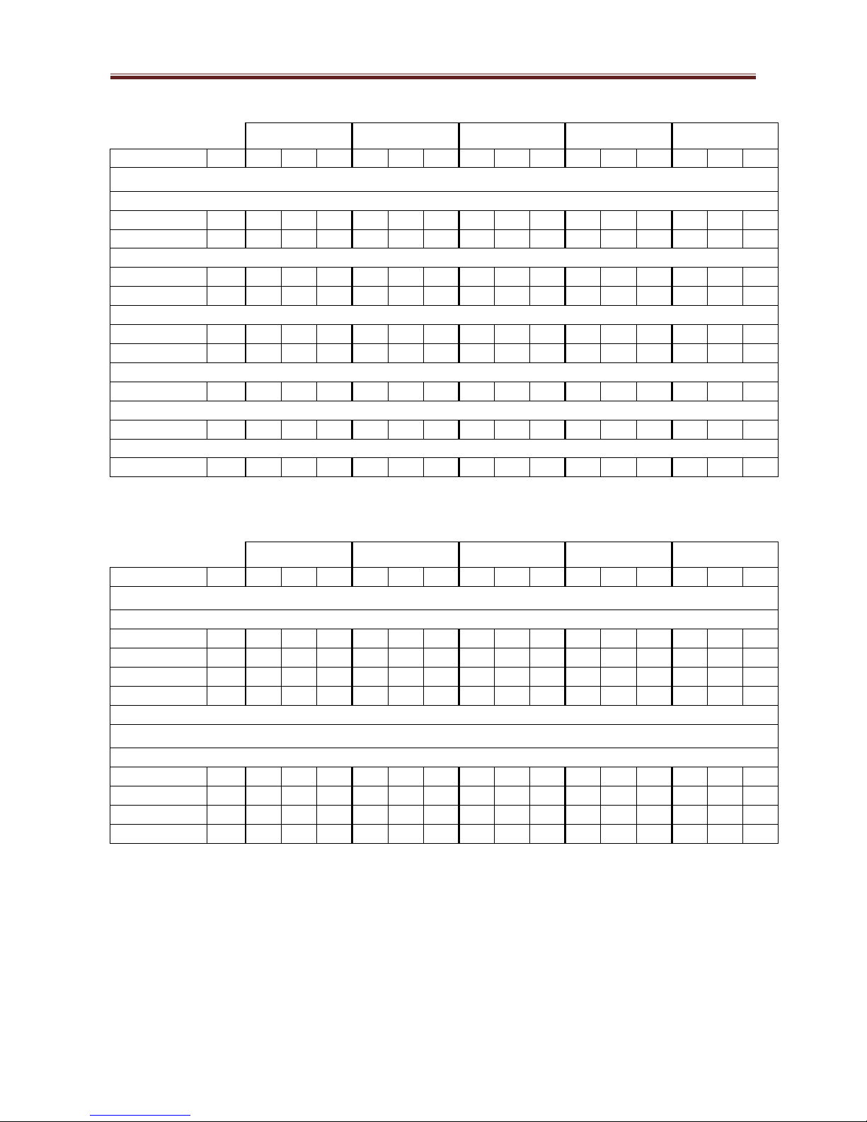
6-TECHNICAL DATA OF OPTIONAL COILS (AC motors)
6.1-Optional main coils
21
31
38
41
81
Speed
min
med
max
min
med
max
min
med
max
min
med
max
min
med
max
4 ROW COIL
COOLING –air 27°C b.s. , 19°C b.u. –water inlet 7°C , outlet 12°C
Total rating
kW
3.1
4.2
4.8
7.8
8.6
8.9
8.8
9.8
10.3
13.7
15.5
17.0
16.6
18.7
20.8
Sensible rating
kW
2.3
3.0
3.4
5.6
6.1
6.3
6.3
6.9
7.3
9.8
11.1
12.0
11.8
13.3
14.7
Water flow
l/h
533
727
816
1340
1469
1523
1516
1674
1776
2354
2660
2922
2846
3217
3562
Δp water
kPa
5.9
10.5
13
10.1
11.9
12.7
12.6
15.2
16.9
7.7
9.6
11.4
10.9
13.6
16.4
HEATING –air 20°C –water inlet 50°C , same water flow of cooling
Rating
kW
4.1
5.6
6.3
10.2
11.2
11.6
11.6
12.8
13.6
17.8
20.2
22.2
21.7
24.6
27.3
Water flow
l/h
533
727
816
1340
1469
1523
1516
1674
1776
2354
2660
2922
2846
3217
3562
Δp water
kPa
5.1
9.1
11.3
8.6
10.1
10.8
10.7
12.9
14.4
6.5
8.1
9.6
9.2
11.5
13.8
6 ROW COIL
COOLING –air 27°C b.s. , 19°C b.u. - water inlet 7°C , outlet 12°C
Total rating
kW
3.7
5.1
5.9
9.7
10.7
11.1
11.1
12.3
13.2
17.2
19.6
21.7
21.1
24.1
26.9
Sensible rating
kW
2.7
3.7
4.2
6.8
7.5
7.8
7.8
8.7
9.2
12.0
13.6
15.0
14.7
16.7
18.6
Water flow
l/h
642
882
1009
1659
1836
1912
1903
2119
2265
2946
3365
3722
3624
4140
4616
Δp water
kPa
6.4
11.5
14.8
15
18
19.4
19.2
23.4
26.5
16.5
21
25.3
24.1
30.6
37.3
HEATING –air 20°C - water inlet 50°C , same water flow of cooling
Rating
kW
4.6
6.5
7.4
11.9
13.2
13.8
13.7
15.3
16.4
20.7
23.7
26.3
25.7
29.5
33.1
Water flow
l/h
642
882
1009
1659
1836
1912
1903
2119
2265
2946
3365
3722
3624
4140
4616
Δp water
kPa
5.5
9.9
12.8
12.6
15.2
16.4
16.3
19.8
22.4
13.8
17.5
21.1
20.1
25.6
31.2
6.2-Optional auxiliary coils
21
31
38
41
81
Speed
min
med
max
min
med
max
min
med
max
min
med
max
min
med
max
ADDITIONAL 2 ROW COIL (4 PIPES)
HEATING - air 20°C - water inlet 70°C , outlet 60°C
Rating
kW
4.9
6.3
7.0
11.6
12.5
12.9
12.9
14.1
14.8
21.0
23.3
25.2
24.7
27.4
30.1
Water flow
l/h
428
553
615
1019
1098
1136
1134
1240
1304
1845
2043
2213
2166
2411
2648
Δp water
kPa
3.9
6.2
7.6
6.7
7.7
8.2
8.2
9.7
10.7
4.4
5.3
6.1
5.9
7.2
8.6
AERTESI srl SOFFIO –Technical manual
Page 10 AER.MT.GB.SOF.001.05.15
6.3-Direct expansion coils
21
31
38
41
81
Speed
min
med
max
min
med
max
min
med
max
min
med
max
min
med
max
4 ROW DIRECT EXPANSION COIL
COOLING –air 27°C b.s. , 19°C b.u. –R410A –evaporation 5°C
Total rating
kW
4.3
5.9
6.7
10.6
11.7
12.2
12.1
13.4
14.2
19.2
21.8
24.0
23.4
26.6
29.5
Sensible rating
kW
2.9
4.0
4.6
7.3
8.1
8.4
8.4
9.3
10.0
12.9
14.8
16.3
15.9
18.3
20.5
COOLING –air 27°C b.s. , 19°C b.u. –R410A –evaporation 7°C
Total rating
kW
3.7
5.0
5.6
8.9
9.8
10.2
10.2
11.3
12.0
16.2
18.4
20.3
19.8
22.5
25.1
Sensible rating
kW
2.6
3.6
4.2
6.5
7.3
7.6
7.5
8.5
9.1
11.6
13.3
14.8
14.4
16.6
18.6
COOLING –air 27°C b.s. , 19°C b.u. –R410A –evaporation 10°C
Total rating
kW
2.8
3.7
4.2
6.7
7.2
7.5
7.4
8.1
8.5
12.2
13.6
14.8
14.5
16.2
17.7
Sensible rating
kW
2.2
3.1
3.6
5.7
6.3
6.5
6.5
7.3
7.8
10.0
11.4
12.6
12.3
14.1
15.9
HEATING - air 20°C –R410A –condensation 40°C
Total rating
kW
2.7
3.6
4.0
6.4
7.0
7.3
7.2
8.0
8.4
11.8
13.2
14.5
14.1
15.9
17.6
HEATING - air 20°C –R410A –condensation 45°C
Total rating
kW
3.5
4.7
5.3
8.4
9.2
9.5
9.5
10.5
11.1
15.4
17.3
18.9
18.5
20.9
23.1
HEATING - air 20°C –R410A –condensation 50°C
Total rating
kW
4.4
5.9
6.6
10.5
11.5
11.9
11.8
13.1
13.8
19.1
21.5
23.6
23.0
26.0
28.8
6.4-Coils for “district-cooling”
21
31
38
41
81
Speed
min
med
max
min
med
max
min
med
max
min
med
max
min
med
max
4 ROW COIL
COOLING –air 24°C b.s. , 18°C b.u. –water inlet 5,5°C , outlet 14,5°C
Total rating
kW
2.0
3.1
3.6
6.6
7.2
7.4
7.4
8.1
8.6
12.0
13.5
14.7
14.3
16.2
17.7
Sensible rating
kW
1.6
2.2
2.5
4.2
4.6
4.8
4.8
5.2
5.5
7.7
8.5
9.3
9.1
10.2
11.2
Water flow
l/h
186
300
342
626
685
707
705
776
817
1145
1288
1399
1369
1542
1690
Δp water
kPa
1.8
4.4
5.6
11.9
14
14.9
14.8
17.6
19.4
13.6
16.8
19.5
18.7
23.2
27.4
6 ROW COIL
COOLING –air 24°C b.s. , 18°C b.u. - water inlet 5,5°C , outlet 14,5°C
Total rating
kW
3.2
4.5
5.1
8.4
9.3
9.6
9.6
10.6
11.2
15.0
17.0
18.7
18.3
20.7
23.0
Sensible rating
kW
2.2
2.9
3.3
5.4
5.9
6.2
6.1
6.8
7.2
9.6
10.8
11.9
11.6
13.1
14.5
Water flow
l/h
306
428
484
801
886
916
912
1010
1069
1432
1623
1782
1741
1973
2191
Δp water
kPa
6.9
12.6
15.8
14.5
17.4
18.5
18.4
22.1
24.5
14.4
18
21.4
20.5
25.7
31
AERTESI srl SOFFIO –Technical manual
Page 11 AER.MT.GB.SOF.001.05.15
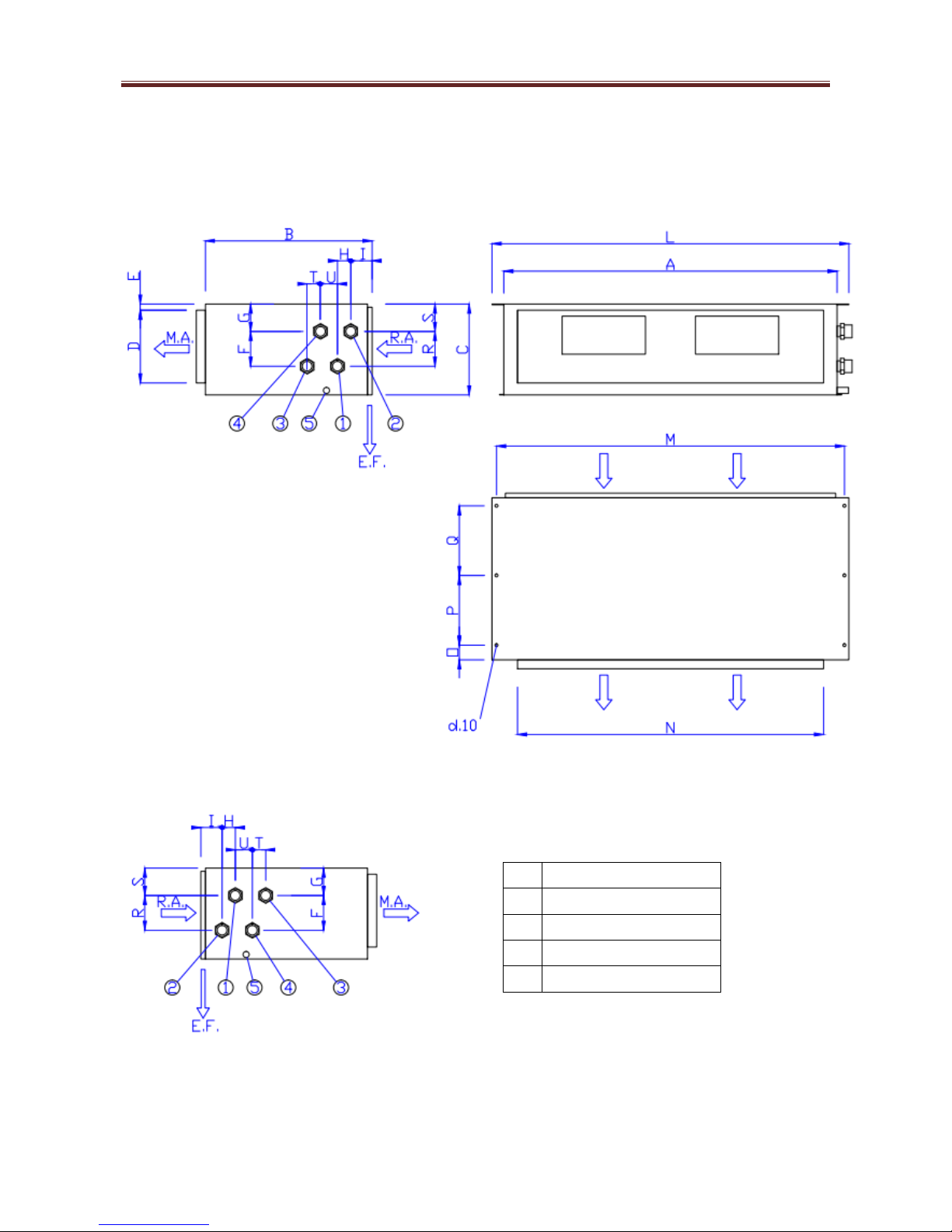
9- DIMENSIONS AND WEIGHTS
9.1-Dimensions and weights for horizontal version
Standard version (right connections)
R.A.= air inlet
M.A.= air outlet
E.F.= filter extraction
Optional version (left connections)
1
Main coil IN
2
Main coil OUT
3
Auxiliary coil IN
4
Auxiliary coil OUT
5
Condensate drain
AERTESI srl SOFFIO –Technical manual
Page 12 AER.MT.GB.SOF.001.05.15
DIMENSIONS (mm)
DIMENSIONS (mm)
21
31
38
41
81
21
31
38
41
81
A
660
1100
1100
1650
1650
M
708
1148
1148
1698
1698
B
550
550
550
650
650
N
570
1010
1010
1560
1560
C
300
300
300
375
375
O
50
50
50
60
60
D
240
240
240
300
300
P
230
230
230
275
275
E
20
20
20
25
25
Q
230
230
230
275
275
F
120
120
120
120
120
R
115
115
115
190
190
G
90
90
90
125
125
S
90
90
90
90
90
H
44
44
44
44
44
T
30
30
30
30
30
I
70
70
70
70
70
U
68
68
68
68
68
L
738
1178
1178
1728
1728
WEIGHT OF THE UNIT (kg)
21
31
38
41
81
3 rows
38
54
55
90
94
3 rows +1 (4 pipes)
40
57
58
94
98
3 rows +2 (4 pipes)
42
60
61
98
102
4 rows
40
57
58
94
98
4 rows +1 (4 pipes)
42
60
61
98
102
4 rows +2 (4 pipes)
44
63
64
102
106
6 rows
44
63
64
102
106

AERTESI srl SOFFIO –Technical manual
Page 13 AER.MT.GB.SOF.001.05.15
9.2- Dimensions and weights for vertical version VC
Standard version (right connections)
R.A.= air inlet
M.A.= air outlet
E.F.= filter extraction
Optional version (left connections)
1
Main coil IN
2
Main coil OUT
3
Auxiliary coil IN
4
Auxiliary coil OUT
5
Condensate drain
AERTESI srl SOFFIO –Technical manual
Page 14 AER.MT.GB.SOF.001.05.15
DIMENSIONS (mm)
DIMENSIONS (mm)
21
31
38
41
81
21
31
38
41
81
A
660
1100
1100
1650
1650
M
708
1148
1148
1698
1698
B
700
700
700
900
900
N
570
1010
1010
1560
1560
C
320
320
320
375
375
O
60
60
60
60
60
D
240
240
240
300
300
P
285
285
285
385
385
E
20
20
20
25
25
Q
285
285
285
385
385
F
115
115
115
115
115
R
120
120
120
181
181
F1
82
82
82
82
82
R1
69
69
69
131
131
G
222
222
222
284
284
S
175
175
175
206
206
G1
240
240
240
300
300
S1
200
200
200
231
231
H
30
30
30
73
73
T
44
44
44
44
44
H1
68
68
68
68
68
T1
94
94
94
94
94
I
128
128
128
140
140
U
184
184
184
217
217
I1
91
91
91
105
105
U1
160
160
160
193
193
L
740
1180
1180
1730
1730
WEIGHT OF THE UNIT (kg)
21
31
38
41
81
3 rows
40
57
58
94
98
3 rows +1 (4 pipes)
42
60
61
98
102
3 rows +2 (4 pipes)
44
63
64
102
106
4 rows
42
60
61
98
102
4 rows +1 (4 pipes)
44
63
64
102
106
4 rows +2 (4 pipes)
46
66
67
106
110
6 rows
46
66
67
106
110

AERTESI srl SOFFIO –Technical manual
Page 15 AER.MT.GB.SOF.001.05.15
9.3-Dimensions and weights for vertical version VD
Standard version (right pipe connections)
R.A.= air inlet
M.A.= air outlet
E.F.= filter extraction
Optional version (left connections)
1
Main coil IN
2
Main coil OUT
3
Auxiliary coil IN
4
Auxiliary coil OUT
5
Condensate drain

AERTESI srl SOFFIO –Technical manual
Page 16 AER.MT.GB.SOF.001.05.15
DIMENSIONS (mm)
DIMENSIONS (mm)
21
31
38
41
81
21
31
38
41
81
A
660
1100
1100
1650
1650
M
708
1148
1148
1698
1698
B
685
685
685
885
885
N
570
1010
1010
1560
1560
C
320
320
320
375
375
O
60
60
60
60
60
D
240
240
240
300
300
P
285
285
285
385
385
E
20
20
20
25
25
Q
285
285
285
385
385
F
115
115
115
115
115
R
120
120
120
181
181
F1
82
82
82
82
82
R1
69
69
69
131
131
G
222
222
222
284
284
S
160
160
160
191
191
G1
225
225
225
285
285
S1
185
185
185
216
216
H
30
30
30
73
73
T
44
44
44
44
44
H1
68
68
68
68
68
T1
94
94
94
94
94
I
128
128
128
140
140
U
184
184
184
217
217
I1
91
91
91
105
105
U1
160
160
160
193
193
L
740
1180
1180
1730
1730
V
30
30
30
30
30
WEIGHT OF THE UNIT (kg)
21
31
38
41
81
3 rows
40
57
58
94
98
3 rows +1 (4 pipes)
42
60
61
98
102
3 rows +2 (4 pipes)
44
63
64
102
106
4 rows
42
60
61
98
102
4 rows +1 (4 pipes)
44
63
64
102
106
4 rows +2 (4 pipes)
46
66
67
106
110
6 rows
46
66
67
106
110

AERTESI srl SOFFIO –Technical manual
Page 17 AER.MT.GB.SOF.001.05.15
9.4-Hydraulic connections and volume of coils
HYDRAULIC CONNECTIONS
21
31
38
41
81
1
Main coil IN
3/4"
3/4"
3/4"
1"
1"
2
Main coil OUT
3/4"
3/4"
3/4"
1"
1"
3
Auxiliary coil IN
3/4"
3/4"
3/4"
3/4"
3/4"
4
Auxiliary coil OUT
3/4"
3/4"
3/4"
3/4"
3/4"
5
Condensate drain pipe
20mm
20mm
20mm
20mm
20mm
Direct expansion-liquid pipe R410A
(to weld)
d.6
d.10
d.10
d.16
d.16
Direct expansion-gas pipe R410A
(to weld)
d.10
d.16
d.16
d.18
d.18
INTERNAL VOLUME OF COILS (litres)
21
31
38
41
81
3 rows
1,1
2,0
2,0
4,0
4,0
4 rows
1,5
2,7
2,7
5,4
5,4
6 rows
2,2
4,0
4,0
8,1
8,1
Auxiliary 1 row
0,4
0,7
0,7
1,3
1,3
Auxiliary 2 rows
0,7
1,3
1,3
2,7
2,7
4 rows/direct expansion R410A
1,0
1,8
1,8
3,6
3,6
10-ACCESSORIES
HYDRAULIC ACCESSORIES
O/VC/VD
A/K/C
V22K
2 way valve ON-OFF 230V
O/VC/VD
K
V42K
2 way valve ON-OFF for 4 pipes
O/VC/VD
K
V23K
3 way valve ON-OFF 230V
O/VC/VD
K
V43K
3 way valve ON-OFF 230V for 4 pipes
O/VC/VD
K
V22MK
2 way modulating valve 0-10V
O/VC/VD
K
V42MK
2 way modulating valve 0-10V for 4 pipes
O/VC/VD
K
V23MK
3 way modulating valve 0-10V
O/VC/VD
K
V43MK
3 way modulating 0-10V for 4 pipes
O/VC/VD
K
PSC
Condensate drainage pump
O/VC/VD
K
VCS
Auxiliary drain pan for valves
O
K
ELECTRICAL ACCESSORIES
TR24
Transformator 230Vac-24Vac , 20VA for modulating valve
O/VC/VD
A
ETBN
Power relay board for SOFFIO 21-31-38-41
O/VC/VD
A

AERTESI srl SOFFIO –Technical manual
Page 18 AER.MT.GB.SOF.001.05.15
ETBN-6A
Power relay board for SOFFIO 81 only
O/VC/VD
A
EH
Electric heater (installed inside the unit)
O/VC/VD
A
EHR
Relay for electric heater
O/VC/VD
A
IPB
Watertight electric box, on the same side of the water connections
O/VC/VD
A
AERAULIC ACCESSORIES
FP
Flat flange (inlet or outlet)
O/VC/VD
A
FRA
Inlet flange with filter extraction from the bottom
O
A
FRAL
Inlet flange with filter extraction from the side
O
A
FRAV
Inlet flange for vertical version with filter extraction from the front
VC
A
GM2
Outlet grill with double regulation
O/VC/VD
B
GRD
Decorative inlet grill
O
B
GR
Inlet grill
O/VC/VD
B
P90
Plenum 90° (inlet or outlet)
O/VC/VD
B
PMA
Air mixture suction plenum
O/VC/VD
B
PD
Plenum (inlet or outlet)
O/VC/VD
B
PGM2
Plenum with outlet grill with double regulation
O/VC/VD
B
PGR
Plenum with inlet grill
O
B
PS
Plenum with spigot (inlet or outlet)
O/VC/VD
B
PRA
Plenum of air regulation
O/VC/VD
B
PB3
Plenum with post-heating coil with 3 rows
O/VC/VD
B
PB4
Plenum with post-heating coil with 4 rows
O/VC/VD
B
SL
Silenced plenum (inlet or outlet)
O/VC/VD
B
BL
Free ducted unit
O/VC/VD
A
ACCESSORIES FOR THE INSTALLATION
TPP
Roof cover
O
B
ZA
Socle set
O
B
FILTRATION
FRAF6
Inlet flange with bag filter class F6
O
B
FRAF7
Inlet flange with bag filter class F7
O
B
FRAF9
Inlet flange with bag filter class F8
O
B
FA1
Washable, wire mesh filter of polypropylene class G1 thickness 6mm
O/VC/VD
A
FA2
Synthetic fiber filter class G3 thickness 20mm
O/VC/VD
A
FA3
Synthetic fiber filter class G4 thickness 25mm
O/VC/VD
A
FA4
Filter of mesh of galvanized steel class G1 thickness 15mm
O/VC/VD
A
FA5
Filter of mesh of galvanized steel class G1 thickness 25mm
O/VC/VD
A
FA6
Aluminum mesh filter class G1 thickness 15mm
O/VC/VD
A
FA7
Aluminum mesh filter class G1 thickness 25mm
O/VC/VD
A

AERTESI srl SOFFIO –Technical manual
Page 19 AER.MT.GB.SOF.001.05.15
A/K/B: A = accessory mounted on the basic unit ; K = accessory supplied in kit, not mounted; B = accessory
supplied assembled, but it is not mounted on the basic unit
O/VC/VD: O= accessory available for horizontal version ; VC = accessory available for vertical version VC ;
VD = accessory available for vertical version VD
According to the table hereafter, the accessories of the group “C” can be directly connected to the structure
of the unit.
The accessories of the group “D” need the accessory FP (if they are connected in outlet) or FRA+FP (if they
are connected in inlet) to be connected to the structure of the unit. Furthermore the accessories of the group
“D” can be connected in series among them.
Group
OUTLET
INLET
FP
-
X (next FRA)
FRA
C
X
FRAL
C
X
FRAV
C
X
GM2
-
X (end duct)
GRD
C
X
GR
-
X (end duct)
P90
D
X (next FP)
X (next FRA+FP)
PMA
D
X (next FRA+FP)
PD
D
X (next FP)
X (next FRA+FP)
AERTESI srl SOFFIO –Technical manual
Page 20 AER.MT.GB.SOF.001.05.15
PGM2
C
X
PGR
C
X
PS
D
X (next FP)
X (next FRA+FP)
PRA
D
X (next FRA+FP)
PB3 - PB4
C
X
SL
C
X (next FP)
X (next FRA+FP)
FRAF6 - 7 - 8
C
X
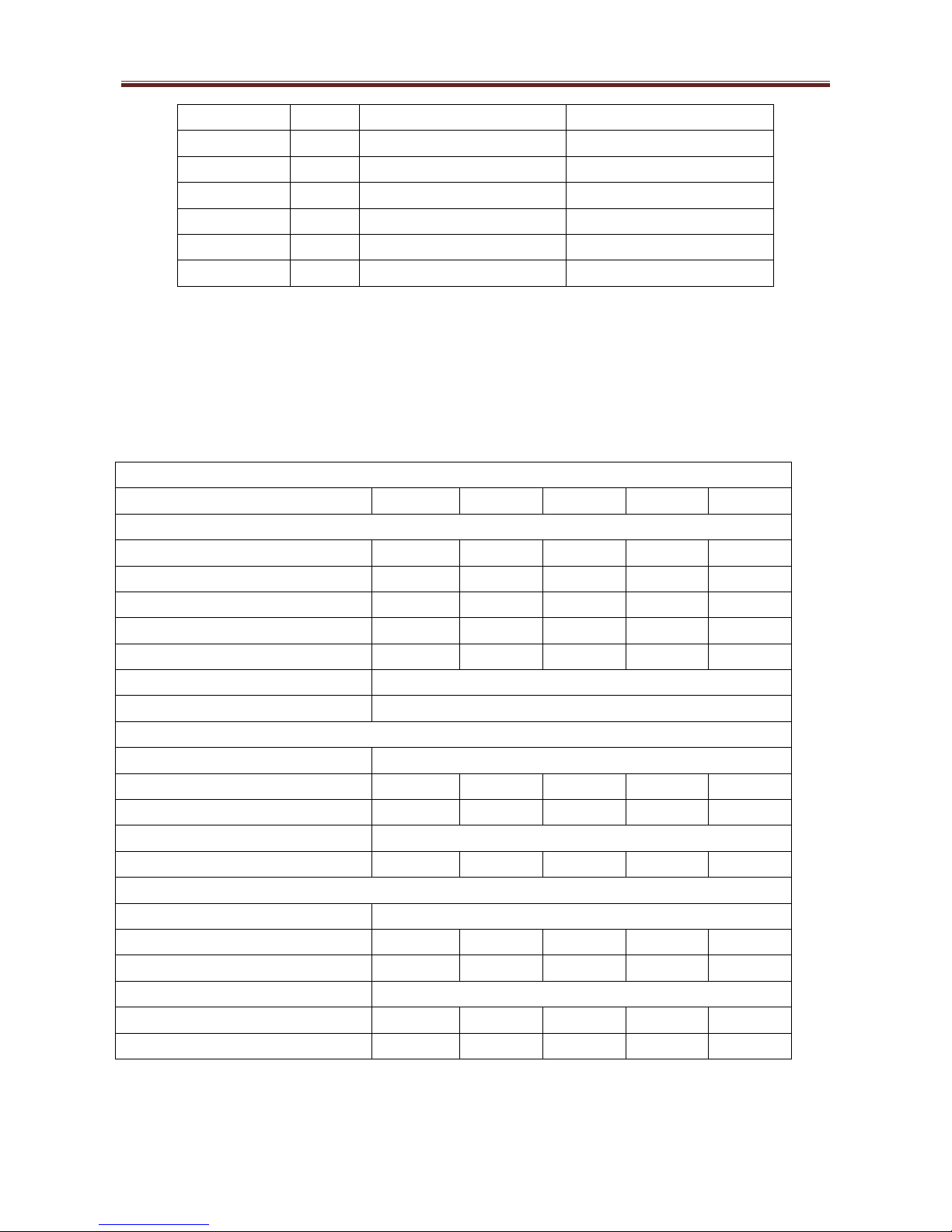
10.1-Valves
We suggest to use motorized valves in order to avoid condensation on the surface of the unit when the fan
doesn’t work.
The valves are supplied in kit, not mounted, to avoid damages during transport and/or installation.
VALVES FOR MAIN COIL
21
31
38
41
81
GENERAL CHARACTERISTICS
Dimensions of the connections
3/4”
1”
1”
1”
1”
Kv (2 way valve)
2,5
4,5
4,5
6,5
8
Kv (3 way valve, linear)
2,5
4,5
4,5
6,5
8
Kv (3 way valve, by-pass)
1,6
3,1
3,1
3,3
6,7
Max differential pressure
1,0bar
0,7bar
0,7bar
1,5bar
1,0bar
Nominal pressure
16bar
Water temperature
4-110°C
ON/OFF ACTUATOR
Power supply
230V-50Hz (24V-50Hz on request)
Power adsorbed
2,5W
2,5W
2,5W
18W
18W
Positioning time
180s
180s
180s
240s
240s
Characteristic (valve + actuator)
N.C. (Normally Closed)
Protection
IP44
IP44
IP44
IP20
IP20
MODULANTING ACTUATOR
Power supply
24V-50Hz
Power adsorbed
1,5W
1,5W
1,5W
18W
18W
Positioning time
8S
8S
8S
240s
240s
Control signal
0-10V
Impedance of control signal
100k
100k
100k
100k
100k
Protection
IP43
IP43
IP43
IP42
IP42
Table of contents
Other Aertesi Air Conditioner manuals


Popular Air Conditioner manuals by other brands


Fujitsu
Fujitsu AST9RSG-W operating instructions

Mitsubishi Electric
Mitsubishi Electric MXZ-A26/32WV installation manual

Trane
Trane MCXE Series Owner's manual & installation manual

Haier
Haier HPP08XCR Installation and user manual

Hotpoint
Hotpoint KL913AM use and care manual

Fintek
Fintek OSLO 3.0 Installation and user manual

International comfort products
International comfort products CAC075 installation instructions

Toyotomi
Toyotomi TAN-A70IV Service manual

Daewoo
Daewoo WM-501 Use & care manual

LG
LG WG5004R Service manual

Daikin
Daikin VRV IV Installer and user reference guide

Mitsubishi Electric
Mitsubishi Electric PEAD-RP1.6EA Technical & service manual