AES PROTEAM iX30T User manual
-1-
I
Full Inverter Swimming Pool Heat Pump
iX30T iX35
Thank you very much for purchasing our product, please keep and read this manual carefully before
you install the heat pump.
Installation & Operation Manual
PROTEAM ix

-2-
Thank you very much for purchasing our please keep and read this manual carefully Packing List
No. Name Qty. Remark
1 Installation & Operation Manual 1
2 Wire-controller 1
3
Wire controller box and sponge pad
(to be installed on the heat pump shell)
1
4 Drain pipe (2 m) 1
5 Drain-pipe connector 1
6 Rubber shock absorber 4
7
Heat Pump Unit
(The pipe connector has been installed on the unit)
1

-3-
Please keep installation manual properly, and read it carefully before using.
The unit must be installed by qualified technicans according to the instructions in this manual.
WARNING: if the unit is installed in locations that are at risk of lightning strikes, lightning
protection measures must be provided.
WARNING: if the pool will be winterized (meaning the heat pump will not be used) all water must be
drained from the unit during winter, or it could freeze inside the unit causing damage to the internal
components.
Content
Accessories…………….............................................................................................................4
Safety...................................................................................................................................5
Heat pump working principle...............................................................................................7
Installation of the unit..........................................................................................................8
Installation of the pipeline..................................................................................................13
Installation of optional accessories.....................................................................................15
Installation and operation of electric devices......................................................................16
Operating Instructions... ....................................................................................................20
Wireless/Remote control................................................. ..................................................27
Adjusting and Initial operation ..........................................................................................32
Operation and maintenance...............................................................................................33
Fault analysis and elimination method...............................................................................35
Technical parameters.........................................................................................................37
After-sale service...............................................................................................................39

-4-
1. Accessories
Each unit produced by our factory comes with the following accessories:
In order for the system to work the following parts are required
No. Name Qty. use
1 Water pump 1 To circulate the pool water
2 Filter system 1 To clean the pool water which passes through the
heat pumps
3 Water pipes system 1 To connect the equipment and circulate the water in
the pool
NOTE
The types and quantity of the water pipes, valves, filter equipment, sterilizing equipment used for the swimming
pool heating/circulation pipe system, will depend on the project design. We do not recommend to install auxiliary
electric heaters in the system.
No. Name Qty. Use
1 Installation & Operation Manual 1 PC User Guide to install the unit
2Wire Controller 1 PC Used for the machine operation interface
3Drain-pipe 1 PC Used for draining the condensate water
4Drain-pipe connector 1 PC To connect the drain pipe to the heat pump
5Rubber Shock Absorber 4 PCS To reduce vibration and noise
6 Heat pump unit 1 SET For heating water

-5-
2. Safety
Range of application:
1.Power supply: 380~415V/3N~50/60Hz.
2.Ambient temperature: -10°C〜43°C:
3.Working water temperature: Min. inlet water temperature 8°C. Max. outlet Water Temperature
40°C. If the system is planned to be used with water temperatures that are outside this range,
please contact Proteam.
●The installation should be done by qualified technicians to prevent leaking, electric shock or fire.
●Check the ground connection: if this is not done correctly, it may cause electric shock.

-6-
When installing the heat pump in a small room, make sure it is well ventilated.
●Don't put fingers or objects into the air inlet or outlet as the rotating fan could cause serious injuries.
●If you smell anything burning, turn off the manual power switch immediately, stop operation and contact
the after-sale service department. Continued abnormal operation may cause electric shock or fire.
●When the unit needs to be removed or re-installed, please ensure that the work is carried out by qualified
technicians. Incorrect installation may result in damage to the heat pump, electric shock, fire, injury, leakage
etc.
●Please ensure that any repairs are carried out by qualified professionals: failure to make proper repairs may
result in damage to the heat pump, electric shock, fire, injury, leakage etc.
● Do no install the unit near flammable sources, as any leakages could cause a fire.
● Make sure the base on which the unit is installed is strong enough to support it.
●Make sure a leakage protection switch is installed to prevent electric shock or fire.
●When cleaning the heat pump, stop operation, switch it off and disconnect the power.

-7-
3.Heat pump working principle
3.1 Heat pump operation
Heat pumps use heat from the sun by collecting and absorbing energy from the outside air.
This energy is then compressed and transferred to the pool water. Your existing water pump
circulates the water through the heat pump, which is normally installed next to the pool
filtration system, and the water warms up. The heat pump timer can be set so that the pump
operates at the times you want: for example, during daylight hours from 9am to 5pm.
The unit contains a fan that draws in outside air and directs it over the surface of the
EVAPORATOR (energy collector). The liquid refrigerant inside the EVAPORATOR coil
absorbs the heat from the outside air and becomes a gas.
The warm gas inside the coil passes through the COMPRESSOR, which concentrates
and increases the heat to form a very hot gas, which then passes through the
CONDENSER (water heat exchanger). It is here that the heat exchange occurs as the
heat from the hot gas is transferred to the cool swimming pool water circulating through
the heat exchanger.
The pool water becomes warmer and the hot gas returns to its liquid form as it flows
through the CONDENSER coil. The gas then passes through the Electronic Expansion Valve
and the whole process begins again.

-8-
Developments in heat pump technology mean that today heat pumps can efficiently
collect heat from the outside air even when the temperature is as low as 7-10°C. This
means that for tropical and subtropical climates the pool can be maintained between 26°C and 32°C.
3.2 Air source heat pump working principle
4 way valve
Water inlet
Water Outlet
Condenser
Gas-liquid
separator
Compressor
Filter
Expansion valve
Filter
Ev aporator
Fan unit
Figure 1
Qc(Heat energy) = Qa(Compressor consumption) + Qb(Heat energy absorbed from ambient environment)
4.Installation of the unit
4.1 Installation Guidelines
●Do not install in locations containing mineral oil.

-9-
● Do not install in locations where the air contains salt or other corrosive gases.
● Do not install in locations with serious power supply voltage fluctuation.
● Do not install in unstable places (without a firm supporting base), such as a car or cabin.
● Do not install near flammable items.
● Do not install in locations with strong electromagnetic forces.
● Do not install in locations with harsh environmental conditions.
4.2 Installation check
● Check that the model, number, name etc, are correct.
● Make sure there is enough space for installation and maintenance/servicing.
● Install in a dry, well-ventilated place and make sure there are no obstructions around the air inlet and
outlet.
● Make sure the supporting base is strong enough and prepared correctly to avoid shocks.
● The power supply and diameter of the cables used must be in accordance with the electrical installation
requirements.
● Electrical installation must comply with the relevant technical standards in the country of operation, and
electrical insulation work must be done.
● The unit must be in an upright position (normal running position) for at least eight hours before running.
4.3 Installation space
Please observe the space requirements indicated below for optimal operation and maintenance.

- 10 -
Figure 2. Horizontal installation space requirements (mm)
4.4 Heat pump dimensions
Figure 3. Heat pump dimensions :iX-30/ix-30T/iX-35
A B C D E F G H I J K
iX-30T/iX-35 738 1084 445 401 187 710 187 102 440 27 17

- 11 -
4.5 Exploded view
Parts Parts
1 Protection grill for fan 15 Water flow switch
2 Front panel 16 Titanium heat exchanger
3 Fan blade 17 Right frame/support
4 Fan motor 18 Manometer/Pressure Gauge
5 Left panel 19 Right panel
6 Left frame/support 20 Controller
7 Evaporator 21 Electrical terminal cover
8Fan-motor mounting bracket 22 Electrical terminal block
9 Upper frame 23 Electrical cable support
10 Electrical box 24 Electronic expansion valve
11 Electrical box cover 25 Reactive resistance
12 Top cover/panel/lid 26 Bottom panel
13 Plastic net 27 Four-way valve
14 Central bracket 28 Compressor

- 12 -
4.6 Installation base for heat pump
Please refer to Figure 4.
A n c h o r b o lt
Drainage tray
Heat Pump
Installation base
Concrete
Anchor bolt
Screw nut/washer
Shock absorb
Heat Pump
Drainage tray
Figure 4 Installation base
4.7 Lifting
●Use four or more soft lifting belts to move/carry the units (see Figure 5).
● Use protective plates on the surface of the units when handling to avoid scratches and deformation.
●Double-check that the support base is strong enough before fixing the unit.
● The heat pump will produce condensation water: remember to provide a drainage channel when making
the installation base.
● Please install the shock absorber provided on the surface of the base (under the feet of the unit).
Figure 5 Lifting diagram

- 13 -
5.Installation of pipes
5.1 Attention
● Prevent air, dust and other material from going into the water pipes.
●Fix the whole system before installing and connecting the water pipes.
● Water inlet and outlet pipes should be protected by an insulation layer.
● Make sure that there is a stable water flow to prevent excessive throttling.
● Do not handle, move or lift the unit by holding the water inlet and outlet pipes: use only the holes on the
base (see Figure 5)
● When connecting the water inlet and outlet pipes, use two pipe wrenches to adjust the two connecting
parts of the pipes; make sure the water inlet and outlet pipes do not twist (see Figure 6).
Figure 6
5.2 Instructions
5.2.1 Symbols
- 14 -
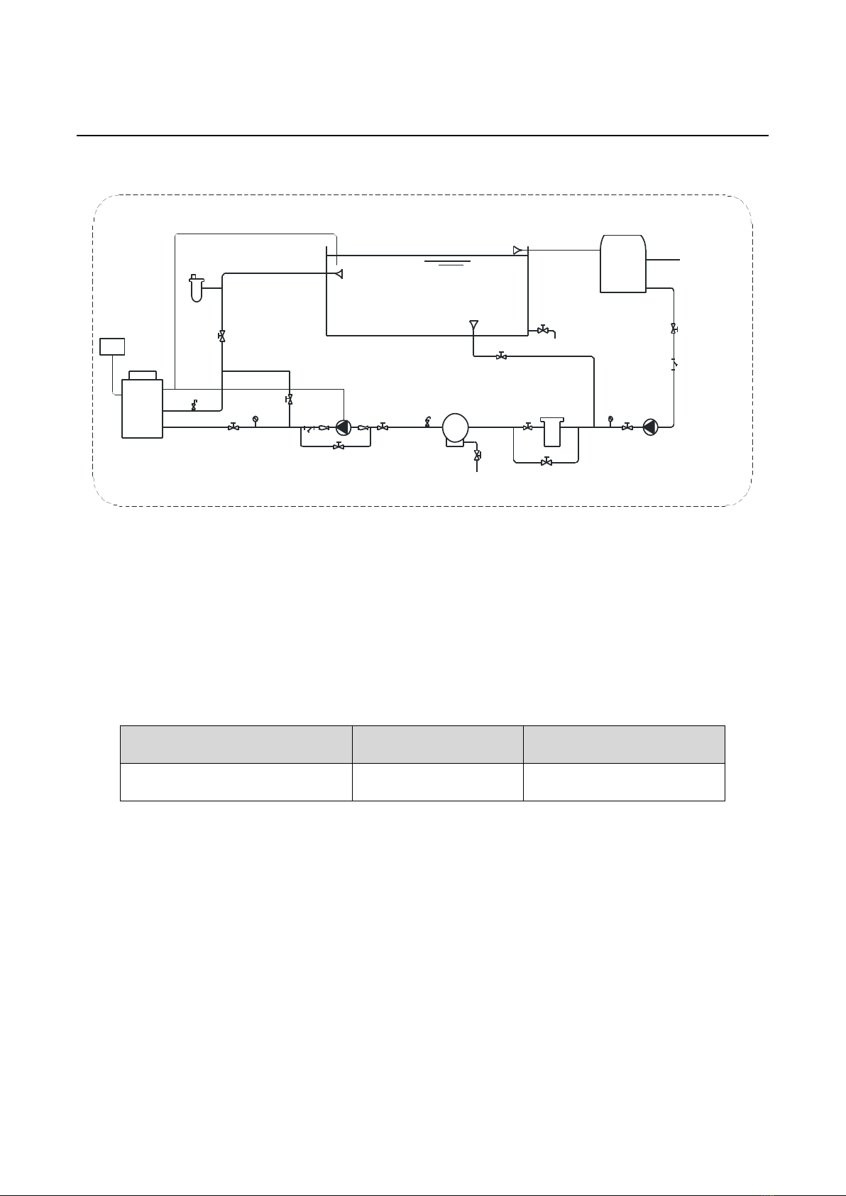
5.2.2 Pipeline installation diagram
Controller
Heat
Pump
Water temp sensor wire .
Swimming Pool
Pump signal wire
Pump
Drainage
Drainage
Feeding water
Figure 7 Diagram(Single unit for reference)
● It is recommended to install a one-way valve for each unit to prevent water back flow.
● Multiple units can be installed as part of a system, but each unit should be controlled independently.
● All pipes and valves should be insulated.
5.2.3 Connection sizes
Model No. Inlet Outlet
ix-30T/ iX-35 DN50 DN50
●The pipe pressure and flow rate should be calculated before selecting the diameter of the pipe, pressure
drop range is 0.3〜0.5 kgf/cm2(3〜5m)head pipe flow rate range is 1 .2〜2. 5 m/s.
●The hydraulic calculation should be made after selecting the pipe diameter. If the resistance is more than
the pump head, then a more powerful pump or larger pipes are required.
5.2.4 Required Water Quality
● Bad quality water will produce more lime scale and sand: this kind of water should be filtered and
demineralized.

- 15 -
●The water quality should be analyzed before operating the unit: PH value, conductivity, chloride ion
concentration and sulphate ion concentration should be checked.
●Acceptable water quality shown below:
PH value Total hardness Conductivity Sulphate ion Chlorine ion Ammonia ion
7~8.5 < 50ppm <200μV/cm(25
℃
) None < 50ppm None
Sulfate ion Silicon Iron content Sodium Ca
< 50ppm < 50ppm < 0.3ppm No requirement < 50ppm
● Suggested filter mesh = 40.
6.Installation of optional accessories
6.1 Selection of the water pump
●The circulation pump is required for the system to operate, there is a terminal connection for the pump
(single phase)
NOTE
For single-phase pumps, please check the wiring diagram.
●Head of circulation pump = height difference between water level and main unit + total pipeline resistance
(determined by the hydraulic calculation) + pressure loss of main unit (see nameplate on heat pump).
NOTE
Multiple units installed in parallel place more demand on the water pump requirement.
6.2 Water pipe selection
●The selection of the water pipe should be based on the actual system specifications
●The flow switch can be installed horizontally or vertically. If installed vertically, the direction of the water
flow must be upwards and NOT downwards.
● The flow switch must be installed on a straight pipeline, and there must be more than five times the length
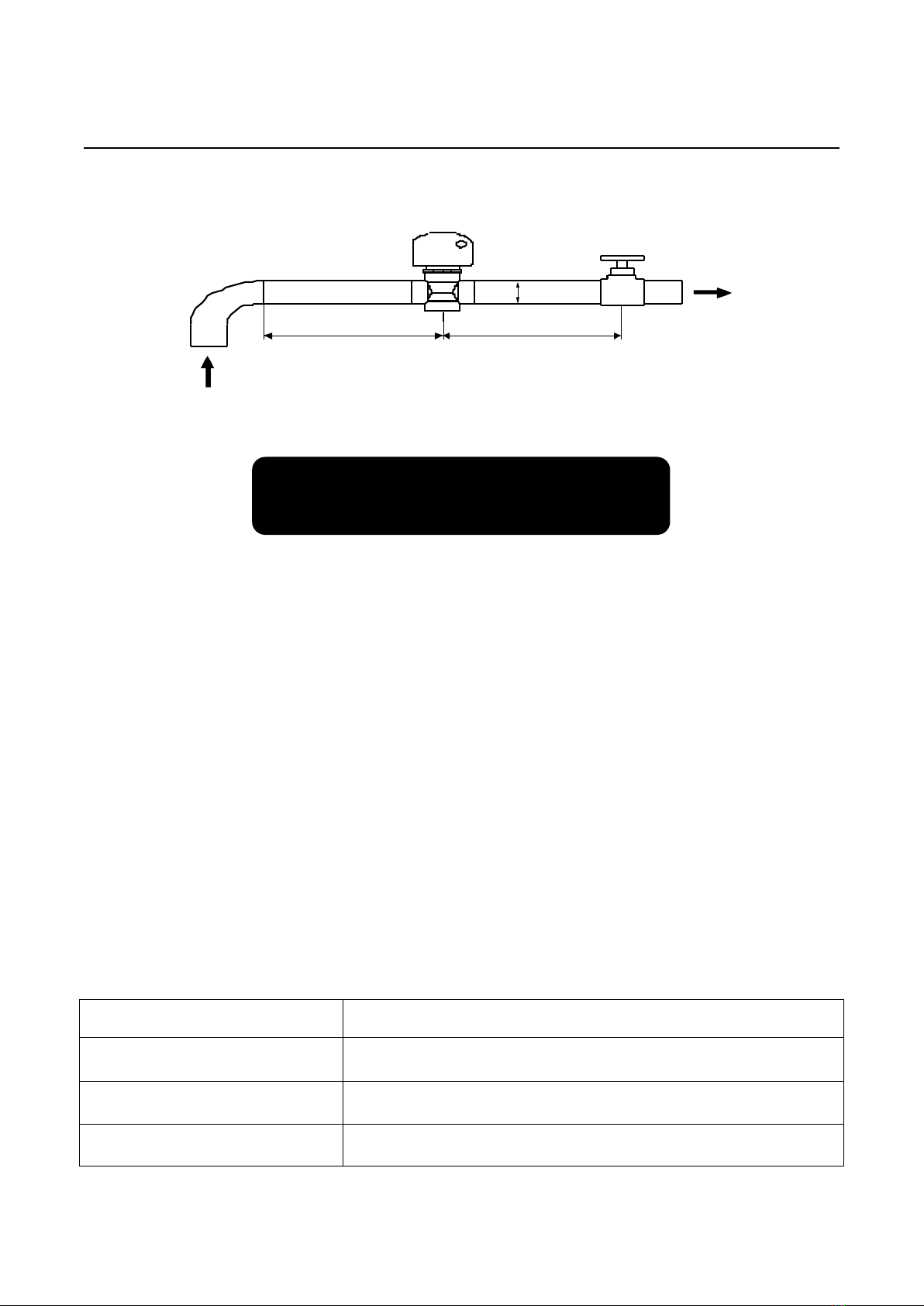
- 16 -
of the pipe diameter on either side of the flow switch (see Figure 8 below). The direction of fluid must follow
the arrow on the controller. The terminal block should be installed in a position that is easy to operate.
A
5A 5A
Figure 8
7.Installation of electrical devices
7.1 Electrical wiring
●The unit should have a dedicated power supply in accordance with the recommended voltage.
●Unit power supply circuit must have an effective external grounding.
●Wiring and electrical connections must be made by qualified professionals in accordance with the wiring
diagram.
●Power line and signal line layout should be neat and cables should not interfere with each other.
●Do not install the units if the power supply specifications are not met.
●After all wiring connections have been completed, check them again carefully before switching on the
power.
7.2 Electrical Wiring Specification
Model Cable Size
iX-30T 5*2.5 mm²
iX-35 3*6mm2
Terminal Terminal cable max. 4 mm²

- 17 -
Figure 9
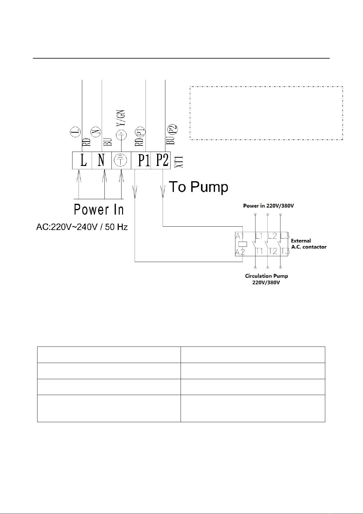
7.3 Circulation pump installation
The heat pump only provides a signal for the circulation pump, A separate A.C. Contactor is required
to connect the circulation pump.
Figure 10
NOTE:
If pump power is less than 250w, connect
the pump according to this drawing.
- 18 -
Figure 11
7.4 Electric wiring diagram
COMP : COMPRESSOR GND : GROUND
AMBT: AMBIENT TEMPERATURE SENSOR WFS: WATER FLOW SWITCH
LOW : LOW PRESSURE SWITCH HIGH : HIGH PRESSURE SWITCH
COIL: EVAPORATOR COIL TEMPERATURE SENSOR OWT/INWT: INLET / OUTLET WATER TEMPERATURE
SENSOR
NOTE:
If pump power > 250w, connect the pump
according to this drawing

- 19 -
Figure 12 Electrical wiring diagram

- 20 -
8.Operating Instructions
Wire controller (Buttons and Icons)
8.2 Start up & Locking
Attention: Before you start the machine, please make sure the filtration pump is running and
there is water flowing through the heat pump.
Hold the button for 3 seconds to switch the heat pump ON or OFF.
This manual suits for next models
1
Table of contents


