Aeson Power TL-LFP Series User manual

Page 1
Installation and Operation
Manual
4.8
to 38.4
kW
h 48Vdc
Battery
Energy
Storage Unit

Page 2
Contents
Part 1 - Safety & Warning..................................................................................................................................3
Part 2 - Product Introduction..............................................................................................................................4
2.1 - Overview..............................................................................................................................................4
2.2 - Working Principle ................................................................................................................................4
2.3- Battery Management System (BMS)....................................................................................................5
2.4- Applications..........................................................................................................................................8
2.5- Battery Model Name.............................................................................................................................8
2.6 - Electric Performance...........................................................................................................................8
2.7 -Structure and Mechanical Performance...............................................................................................9
2.8 -Appearance & Mechanical Drawing...................................................................................................10
Part 3 - Technical Characteristics....................................................................................................................11
3.1 - Discharge Performance.....................................................................................................................11
3.2 - Charge Performance......................................................................................................................... 12
3.3 - Constant Current Discharge Table.................................................................................................... 12
3.4 - Constant Current Discharge Table................................................................................................... 13
Part 4 - Operation & Maintenance .................................................................................................................. 12
4.1 - Requirements for Operation Environment .........................................................................................14
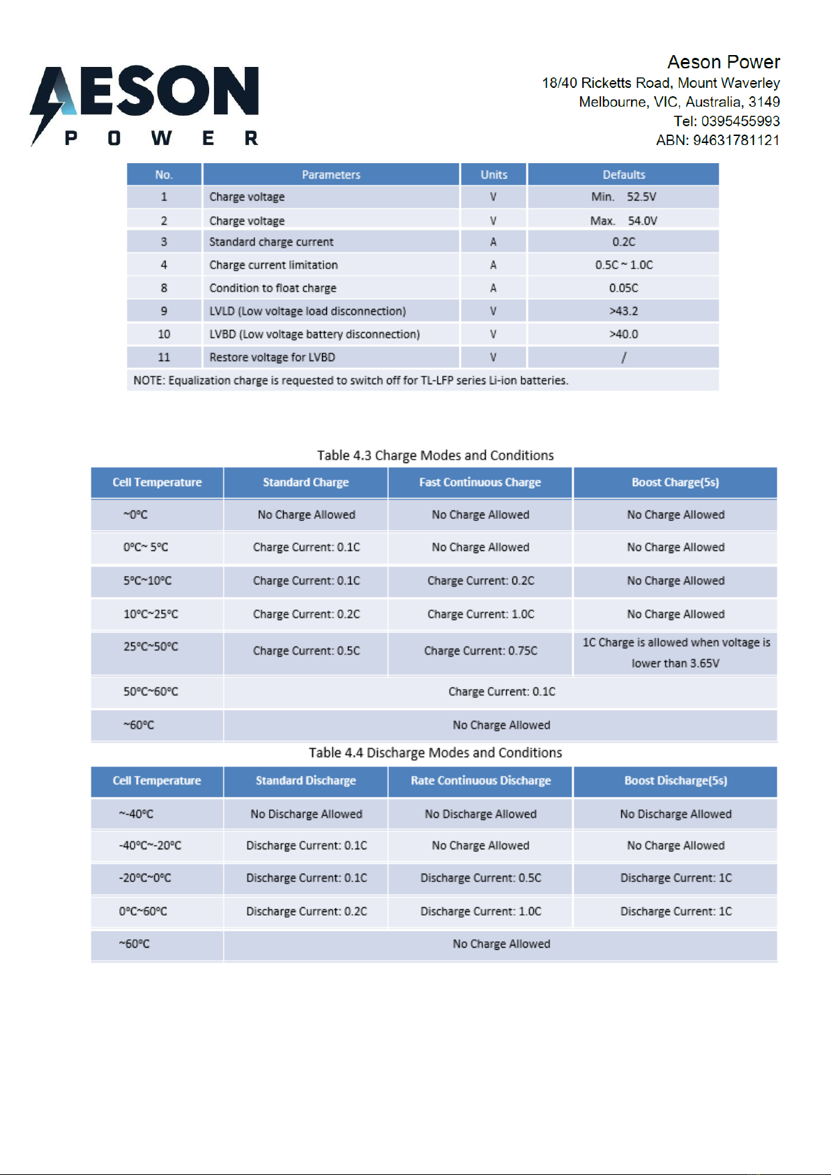
4.2 - Parameter Settings of Power Plant....................................................................................................14
4.3 - Charge/Discharge Modes and Conditions.........................................................................................15
4.4 - Layout of Front Panel.........................................................................................................................15
4.5 - Shipment ............................................................................................................................................17
4.6 - Installation ..........................................................................................................................................17
Unboxing & Inspection ........................................................................................................................ 17
Preparation for Installation.................................................................................................................. 17
Installation of Rack without batteries installed....................................................................................17
Installation of Rack with batteries installed.........................................................................................21
4.7 - Storage............................................................................................................................................... 26
4.8 - Maintenance.......................................................................................................................................26
Part 5 - Troubleshooting & Solutions................................................................................................................27
Annex 1 - Instructions for LED Flicker............................................................................................................... 27
Annex 2 - Instructions for Adding Dialer............................................................................................................ 29
Annex 3 - Communication Protocol for RS232 and RS485...............................................................................30
Annex 4 –Rack Tech Data................................................................................................................................31
Annex 5 –Installation Recommendations..........................................................................................................32

Page 3
Part 1 - Safety & Warning
The TL-LFP series LiFePO4 battery system installation, operation and maintenance should
follow important recommendations in this manual:
▪The equipment must be installed by a licensed electrician.
▪Battery maintenance should be carried out by experienced professionals, fullytrainedinsafety
measuresand aware of the risks and dangers presented by the battery.
▪
Note:
Beware of the risk of electric shock by heavy current in case of battery short circuit!
Before commencing work:
•Remove watches, rings and other metal object from your hands;
•Use only tools with insulated handles;
•Please check if the package box is intact. If the box is damaged - immediately notify the supplier;
•If you find leaking liquid or white powder residue on product –stop the operation.
During the operation:
•Do not place tools or metal objects on the battery;
•Disconnect the mains AC power supply to the battery system;
•Do not use or store the battery near to the high temperature source;
•Avoid open fire near the battery;
•Avoid using liquids or other objects filled with liquid near the battery;
•Do not open or cut the battery;
•Do not to hit, throw or step on the battery;
•Use only special communication cable set between battery module(s) and charging equipment;
•The charge and discharge of the battery must be conducted within parameters set in this Manual;
•The output interface of the battery system is LIVE and under dangerous voltage when the mains
power supply is OFF - beware of electric shock or battery shortcircuit during the operation;

Page 4
Part 2 - Product Introduction
2.1 - Overview
TL Series Lithium-Ion batteries is a range of batteries packed with advanced LiFePO4
technology and possessing intelligent integrated BMS.
The TL battery range has the advantages of:
- Long cycle life;
- Light weight;
- Small size;
- Safety;
- Being environmentally friendly.
Lithium-Ion batteries of the TL Series can be used in a wide variety of indoor and outdoor
applications.
2.2 - Working Principle
The communication standby power supply (module) consists of multiple lithium iron
phosphate battery cells connected in series, and controlled by the dedicated high
performance and high reliability Battery Management System (BMS).
The +/- power output cables of the battery are to be connected to the +/- terminals of the
charging device.
When the mains / solar power is insufficient for the load or is interrupted, the battery will
provide the power supply to the load without delay, until the mains / solar power supply is
restored. In the case of the outage continuing for longer time than the battery has been rated
for - the BMS will disconnectthe battery from the load in order to protect the battery from over-
discharge.

Page 5
2.3- Battery Management System (BMS)
The TL–LFP Series battery modules are equipped with technologically advanced Integrated
Smart BMS.
Features of the BMS are described below:
Overcharge Protection
When the voltage of any cell comprising a module, is greater than the Overvoltage setting,
and the duration of the Overvoltage status exceeds the set time delay of the overcharge
protection, the OV Protection plate closes the MOSFET on the charging circuit and the
charging is interrupted.
When, after the OV status occurs, - the highest voltage cell indicates the voltage reduction to
the overcharge recovery mode, or below - the OV Protection plate judges that the overcharge
conditionis over. Followingthat, the charging MOSFET is open,the charger starts to supply
the battery module, and the green RUN light on the protection plate lights up signalling that
the charging is ON.
During the Overcharge condition the battery module can still discharge on the load.
Over-discharge Protection
In the case of any cell within the module, developing voltage that is lower than the over-
discharge setting, and such condition lingers longer than the over-discharge time-delay setting
–the protection plate judges that the module is in state of Over-discharge. The green RUN
light and red ALM light are both extinguished, the MOSFET on the discharge circuit closes
and the battery module discharge on the load is interrupted.
When over-discharge (undervoltage) condition occurs, the protection plate is de-activated.
When the charger supply is restored –the protection plate gets re-activated .
Overcurrent/short circuit protection and recovery
When the discharge current exceeds the short-circuit protection current settings, and the
duration of such current exceeds the time-delay of the short-circuit protection setting -
- the red ALM light will come on, and
the protection plate enters the overcurrent / short-
circuit protection status, under
which charge / discharge modes are prohibited.
After the protection plate entered the overcurrent / short-circuit protection condition, it will lock
the OV/SCprotectionstatus until time the charger restores the power supply.

Page 6
Heat Management
The thermal management BMS function can be described as follows: if the battery temperature
exceeds the set normal working parameters (higher or lower), the alarm will be raised - red ALM
light will come on and the battery will be disconnected.
When the temperature of the battery, after having been disconnected due to over-temperature
condition, drops to the set value of normal working parameters, the BMS reconnects the battery
to the load / charge, and the red ALM light is off.
The BMS temperature sampling accuracy is less than
± 2°C within the operating temperature
range. Four battery temperature detection points and one ambient temperature detection
point are supported by default. Maximum available number of temperature detection points
–16.
Battery internal heater
VHR TL48150LFP is equipped with an internal heater. The heater is rated 100W. If the battery is not under
charge
and the BMS sampling facility detects the ambient temperature that is below
0
℃ -
the BMS will turn the
heater ON.
The heater is optional for other models.
Battery capacity calculation function
To calculate the State Of Charge (SOC) of the battery –the Amper-Hour Integral and Open
Circuit Voltage (OCV) methods are implemented. The combination of adjustment of the
algorithm, the higher precision data and the independent clock system - ensures accuracy
(≤ ± 2%) of the SOC estimation.
Balancing Function
If the module battery pack is fully charged, and one of its cells has the voltage set to start the
equalization and at the same time, the cell’s maximum voltage difference is greater than the
equalization voltage difference –this cell activates the equalisation function.
The battery module is capable of conducting equalization on 7 channels simultaneously. The
maximum equalization currentaround 75mA. The equalization balancing process will be finished
when the voltage difference of the cells is less than pre-set value.

Page 7
Sleep and Wake Function
No.
Sleep condition
Wake-up condition
Remark
1
In the idle state (no charge, discharge, no
communication), the lowest voltage of any
cell is lower than the set sleep voltage (can be
set), after 30 minutes, enter normal sleep.
Charge and discharge,
communication, reset
button, soft switch
The battery with a
soft switch can be
wakened up
2
When the minimum cell voltage is lower than
the cell over-discharge protection value (can
be set) or the total voltage is lower than the
overall over-discharge protection value (can
be set), and after 1 minute, the under-voltage
sleep is entered.
Charge, reset button,
soft switch
The battery with a
soft switch can be
wakened up.
3
Battery will enter to normal sleep after
keeping idle state (no charge and discharge,
no communication) for 24 hours.
Charge and discharge,
communication, reset
button, soft switch
The battery with a
soft switch can be
wakened up
4
Forcing sleep through the host computer or
soft switch
Reset button, soft switch
N.A.
Communication function
Battery communicate with a computer, server or host through RS485, upload and save the
collected
information. CAN bus communication, 3G/4G communication and Bluetooth
communication can be optioned.
Anti-theft function
When the external load is disconnected, the BMS cannot detect the load resistance, and it will
enter into a locked state, unable to conduct charging and discharging
Note: 1. Please refer to “Specification of each models” for detail BMS parameter setting value.
2. LCD display screen is provided as an option.
3. Anti-theft function is provided as an option.
4
. Thermal management in low temperature heating and high temperature heat dissipation
is optional.

Page 8
2.4- Applications
▪Telecommunication
▪Indoor distribution system
▪Energy storage system
2.5- Battery Model Name
2.6 - Electric Performance
Table 2.1 - Battery Model & Electric Performance

Page 9
2.7 -Structure and Mechanical Performance
Table2.2 - Mechanical Performance

Page 10
2.8 -Appearance & Mechanical Drawing

Page 11
Part 3 - Technical Characteristics
3.1 - Discharge Performance
Fig. 3.1 - Constant Current Discharge Curve of TL-LFP Series @25℃
Fig. 3.1 - Discharge Curve of different temperature of TL-LFP [email protected]

Page 12
3.2 - Charge Performance
Fig. 3.3 - Charge Characteristic with Various Current Limitation of TL-LFP Series
3.3 - Constant Current Discharge Table
Table 3.1Constant Current Discharge Table(25℃)

Page 13
3.4 - Constant Current Discharge Table
Part 4 - Operation & Maintenance
4.1 - Requirements for Operation Environment
4.2 - Parameter Settings of Power Plant
Lead-acid batteries can be replaced by lithium battery of TL-LFP series if power is matched. Table 4.2
Parameter settings of power plant for lithium-ion battery.
Table 4.2 - Parameter Settings of Power Plant for TL48V-LFP Series Batteries
Page 14
4.3 - Charge/Discharge Modes and Conditions

Page 15
4.4 - Layout of Front Panel
Table 4.5 - Instruction for Layout of Front Panel
No.
Marks
Functions
Detailed Information
1
SOC
Indicators for
capacity
There are four green LED lights in front panel indicating SOC.SOC is short for
state of charge. Each SOC LED light represents 25% of rated capacity.
Detailed information is
shown in Annexed Table 1.1.
2
ALM
Indicator for
alarms
There is one red LED light in front panel indicating alarms. Detailed
information is
shown in Annexed Table 1.2.
3
RUN
Indicator for
running status
There is one green LED light in front panel indicating running status.
Detailed
information is shown in Annexed Table 1.2.
4
ADD
Address of
communication
ADD is applicable to modules connected in parallel. ADD consists of four
binary bits,
and maximum quantity of batteries connected in parallel is
64pcs (2^6). Detailed
information is shown in Annex 2.
5
RS232
Up-link
communication
port
It is adopting RS-232 series port to upload data. Contents of data transmit
include BMS
parameters, battery running status, alarms, etc. Generally,
speed rate of RS-232 is
200bps. RS232 up-link communication can be
available for the battery module with a
binary communication address of
0000
(Master PACK). Protocol for RS232
communication is shown in Annexed Table 3.1
1
2
3
4
5
6
7
8
8
9

Page 16
6
RS485
Cascading
communication
port
It is adopting RS485 series port communication pattern to upload data.
Communication
of modules connected in parallel (Slave PACKs) is available
through RS 485. Data of
slave PACKs will be transmitted to Master PACK.
Protocol for RS232 communication is
shown in Annexed Table 3.2
7
RESET
Reset button
Press RESET button when abnormity occurs to assure stability of battery
performance.
8
Battery
Output
Battery
Output
Using terminals with two or four cores. Polarities are +, -, +, - from left to right.
The two ‘+’and ‘-’are equal relatively.
9
Power
Button
ON/OFF Soft
switch
When battery is turned-off, battery get into sleep mode, and cuts-off output,
power and alarm outputs.
4.5 - Shipment
The battery system will either come in 2 different packaging solutions depending on your
needs, the first option will be shipped as a complete battery system ready to be installed and
connected at site. The second solution is shipped in 2 parts with batteries removed from the
rack to assist the customer with site requirements. All options are shipped on pallets that will
either require a forklift or pallet jack for final positioning. With the second option for the parts
are broken down on pallets for a 2-person manageable lift to final positioning. Violent vibration,
impaction or squeezing should be avoided in the transport process; neither rack or batteries
should be exposed to sunlight nor rain. The rack and batteries shall be shipped by normal
transportation such as by road, by train, by ocean or by air.
4.6 - Installation
Unboxing & Inspection
•
Please read this manual before installation.
•
Please inspect the package before unboxing, if any damage with contents, please contact
the supplier as soon as possible.
•
This device shall be installed and operated by professionals.
Preparation for Installation
•
Rack & batteries shall not be placed in direct sunshine or close to a heat source.
•
Rack shall be installed in place with good ventilation to assure enough heat
dissipation.
•
Rack shall be placed in an area with clean ambient temperature with low humidity not
exceeding 25 degree Celsius.

Page 17
Removal of Rack from shipping Pallet
1) Rack with no batteries installed.
•
Rack transport mounting screws will need to be removed before final positioning.
•
Remove covers in the bottom of the rack as shown in the picture as shown below to gain
access to the transportation bolts and plates.
•
Using a shift, spanner or socket, remove the M12 nuts and bolts plus the transportation
plates from the pallet.
•
Once the rack is free from the pallet, lift the rack from the pallet and place on the ground.
•
Remove bottom side panels on the rack so that a pallet jack or set of furniture lifters can
be placed underneath the rack to move into its final position.
•
Once in final position, start installing the batteries into the rack, please note each battery
has been labelled with a number on the front of them for placement back into the rack.
The lifting of the batteries back into the rack requires a 2 person lift to safely install.
•
Check all DC circuit breakers are off, and all batteries are off before reconnecting the pre
wired battery cabling to each battery, please note all cabling is black but is marked with
red and black heat shrink to differentiate between positive and negative battery cabling
and terminals on the battery.
Remove cover at each end of the rack as shown in the below pictures to gain access to
the transport bolts

Page 18
The transport bolts are M12, use shifters, spanners or sockets to remove these bolts to
free the rack from the pallet.
Once transportation Screws have been removed from the Rack, it is safe to remove the rack
from the pallet, please note to remove the rack from the pallet it is recommended the use of
more than 2 people to safely lift the rack from the pallet and on to the floor.
Once the rack is on the ground, remove the side covers to insert pallet jack or furniture lifters
to move into its final position.

Page 19
Below are recommended furniture remover dollies to lift and move the rack into the final
location.
•
Insert battery module into rack, using the two fixing handles of each battery module and
use the M6 screws to fix in to position.
•
Connect ‘+’ of the Battery positive terminal to red cables, and connection ‘-’of the Battery
negative terminal to black cables.

Page 20
Installation of Battery Modules if supplied under option 2
1) Rack with batteries installed.
•
Rack transport mounting screws will need to be removed before final positioning.
•
Remove covers in the bottom of the rack as shown in the picture as shown below to gain
access to the transportation bolts and plates.
•
Using a shift, spanner or socket, remove the M12 nuts and bolts plus the transportation
plates from the pallet.
•
Remove bottom side panels on the rack so that a set of furniture lifters can be placed
underneath the rack.
•
If a fork lift is available, use to remove the rack from the pallet. Otherwise use the below
procedure.
•
Once the rack is free from the pallet, Use a saber saw or hand saw to remove certain
sections of the pallet as pictured below so the furniture lifters canbe inserted on both sides
of the rack, pump the furniture lifters up so the rack is lifted above the pallet by 3 to 5mm.
Check the furniture lifters are secure and safe to handle the weight of the rack with the
installed batteries, then cut off the front section of the pallet and pull the pallet out from
underneath the rack. Once the pallet has been removed from underneath the rack let the
furniture lifters down so the rack is on the ground.
•
Now the rack is on the ground the furniture lifters or a pallet jack can be used to move into
its final position.
This manual suits for next models
2
Table of contents


