Growcol GW51.2V100Ah User manual

USER
MANUAL
Version:01.00
GW51.2V100Ah
Innovative Power

CONTENTS
1 Foreword.................................................................................................................................................
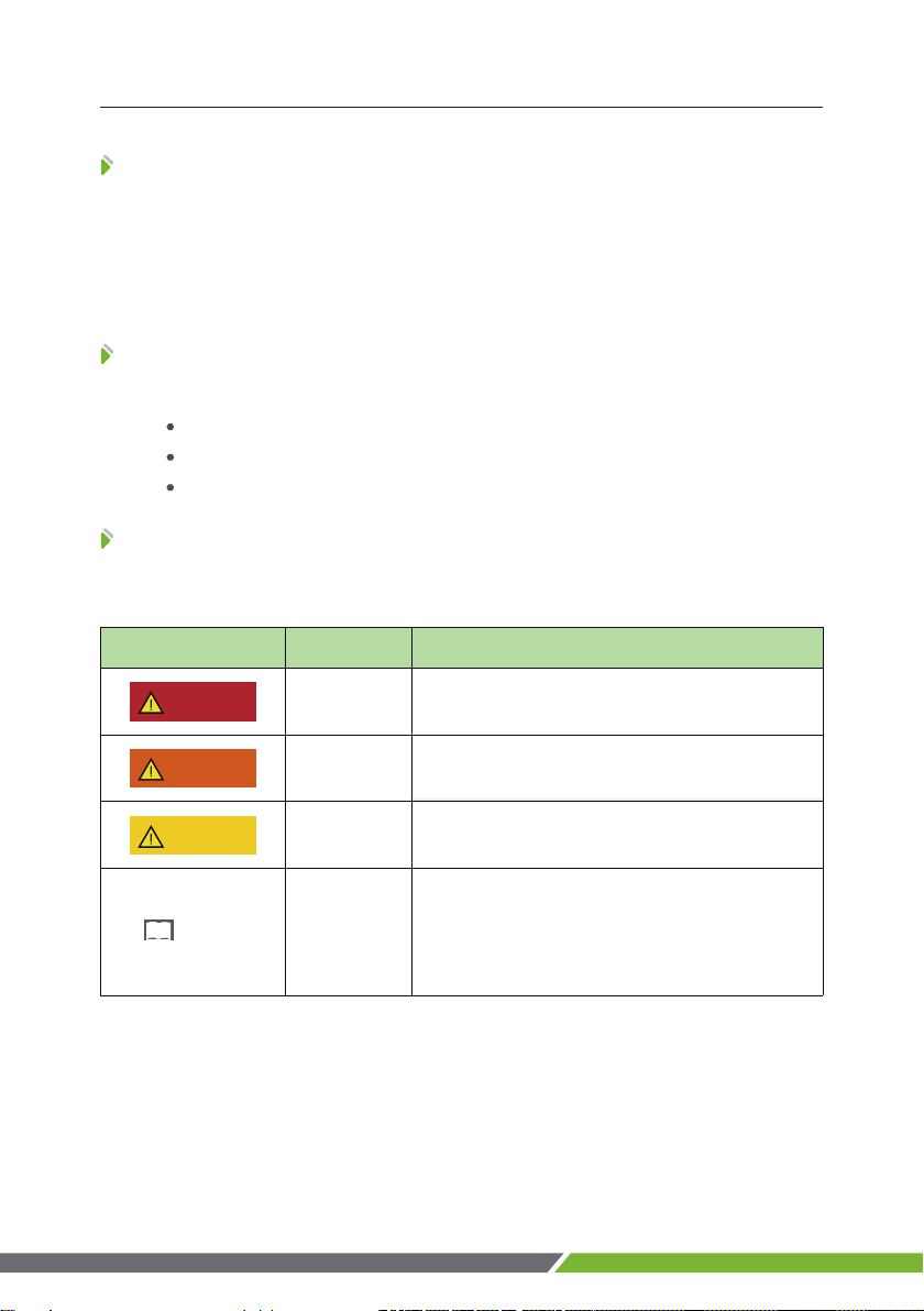
2 Safety........................................................................................................................................................
2.1 Safety Precautions......................................................................................................................
2.2 Abuse Operation.........................................................................................................................
3 Overview..................................................................................................................................................
3.1 Product Description...................................................................................................................
3.1.1 Features...............................................................................................................................
3.1.2 Basic Functions.................................................................................................................
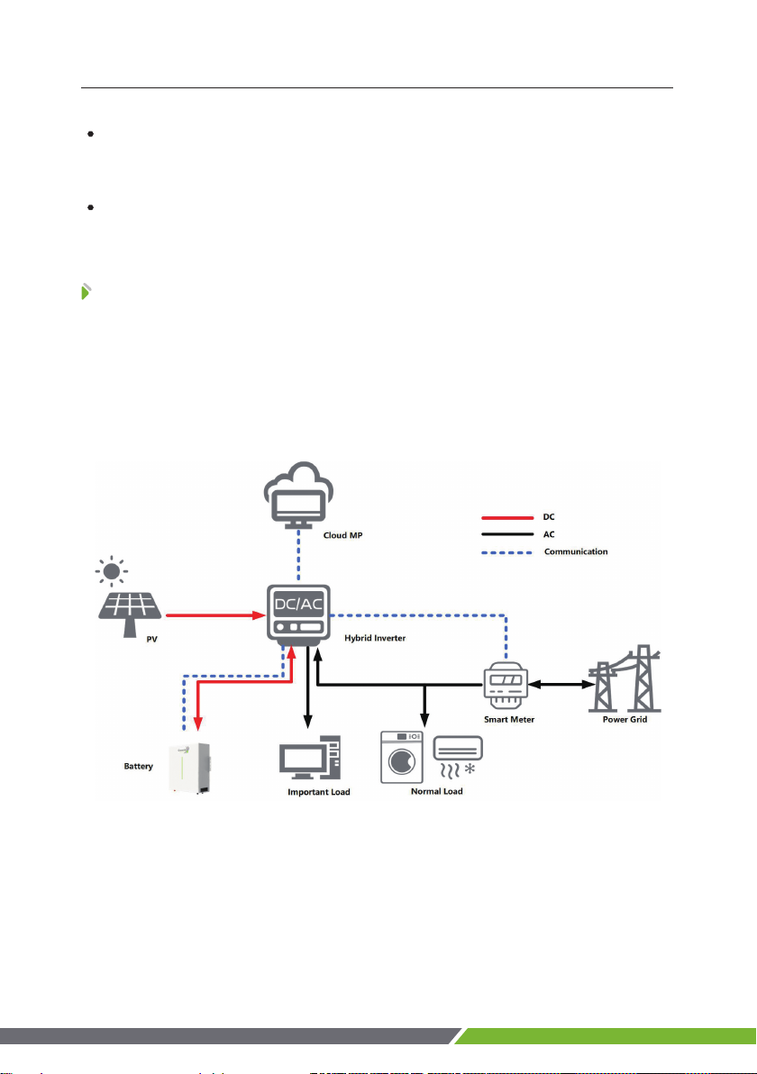
3.2 Application Scenario.................................................................................................................
4 Application Description.....................................................................................................................
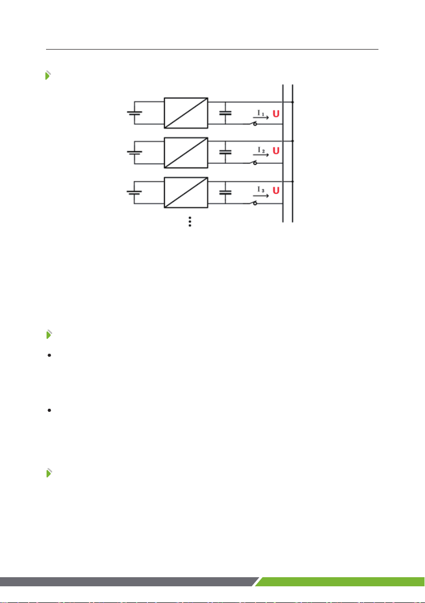
4.1 Parallel Connection Application............................................................................................
4.2 Low-temperature Application................................................................................................
4.3 Low Battery-capacity Storage (SOC≤5%)...........................................................................
4.4 Application of Nearing the Ocean.........................................................................................
5 Product Introduction..........................................................................................................................
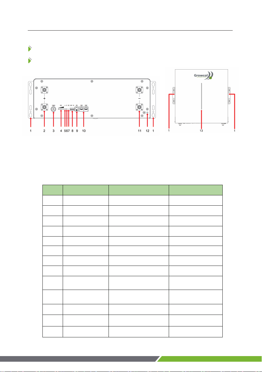
5.1 Panel Introduction......................................................................................................................
5.1.1 Panel Function...................................................................................................................
5.1.2 Indicator Description......................................................................................................
5.1.3 DIP Address........................................................................................................................
5.1.4 Communication Port Definition..................................................................................
6 Installation..............................................................................................................................................
6.1 Tools Preparation........................................................................................................................
6.2 Unpacking and Inspection.......................................................................................................
6.3 Preparing for Installation.........................................................................................................
6.4 Installation....................................................................................................................................
6.4.1 Wall Mouning...................................................................................................................
6.4.2 Rack Mouning...................................................................................................................
6.5 Cable Connection.......................................................................................................................
6.5.1 Power Cable Connection...............................................................................................
6.5.2 Communication Cable Connection............................................................................
6.5.3 120Ω Resistor Connection............................................................................................
7 Power On.................................................................................................................................................
7.1 Power-on Operation (For professionals).............................................................................
7.1.1 Power-on Check................................................................................................................
7.1.2 UIWare Configuration.....................................................................................................
7.2 Power System Parameter Setting................................................................................................
8 Shipment & Maintenance & Storage...........................................................................................
8.1 Shipment.......................................................................................................................................
8.2 Maintenance................................................................................................................................
8.2.1 Battery Maintenance Considerations.......................................................................
8.2.2 Routine Maintenance.....................................................................................................
8.3 Battery Storage...........................................................................................................................
9 Trouble Shooting.................................................................................................................................
10 Warranty...............................................................................................................................................
11 Abbreviations.....................................................................................................................................
1
2
2
2
3
3
3
3
4
5
5
5
5
6
7
7
7
8
10
11
11
12
12
13
13
13
16
18
18
20
21
22
22
22
23
24
25
25
25
25
26
27
28
29
30

This document is mainly applicable to the following engineers
Technical Support Engineer
Installation Personnel
Maintenance Engineer
1
1 Foreword
This user manual mainly introduces product introduction, application descrip-
tion, installation instructions, power-on instructions, maintenance instructions and
provides instructions the GW51.2V100Ah LFP battery pack for technical support
engineers, maintenance engineers and users.
Reader
Overview
Signs
The following signs may appear in this article, and their meanings are as follows.
Sign Meaning Description
Danger Indicates a hazard with a high level of risk that will cause
death or serious injury if not avoided.
WarningIndicates a hazard with a moderate risk that may cause
death or serious injury if not avoided.
Notice Indicates a hazard with a low level of risk that may cause
minor or moderate harm if not avoided.
Explanation
Supplementary explanation of key information in the
main text."Explanation" is not safety warning information,
and does not involve personal, equipment and
environmental damage information.
DANGER
WARNING
NOTE
ATTENTION

Before carrying out battery work, you must read carefully the safety precautions
and master the correct installation and connection methods of the battery.
Prohibit to turn it upside down, tilt, or collide.
Prohibit to short-circuit the positive and negative poles of the battery,
otherwise it will cause the battery to be damaged.
Prohibit to throw the battery pack into a fire source.
Prohibit to modify the battery, and it is strictly prohibited to immerse the
battery in water or other liquids.
DO NOT place installation tools on the battery during battery installation.
DO NOT disassemble, squeeze, bend, deform, puncture, or shred the
battery without the authorization of authorized dealers.
DO NOT exceed the temperature range, otherwise it will affect the battery
performance and safety.
The battery circuit must be kept disconnecting status during installation
and maintenance operations.
Check the battery connection end bolts regularly to confirm that the bolts
are tight.
2
2 Safety
2.2 Abuse Operation
2.1 Safety Precautions
The battery pack needs to avoid abuse operations under the following (includ-
ing but not limited to) conditions:
Abuse Operation Protection Description
If the positive and negative poles are connected reversely,
the battery will be directly damaged.
External short circuitIf the battery pack is short circuited externally, the battery
will be directly damaged.
Series connection application
The battery pack does not support the application of
battery packs in series. If the battery packs are forced to be
connected in series, the batteries may be directly damaged,
and may even cause fire, explosion and other dangers.
Reverse connection of positive
and negative poles

3
3 Overview
The GW51.2V100Ah product use lithium iron phosphate (LFP) as the positive
electrode material. It can be widely used in energy storage systems such as residen-
tial energy storage, back-up power, and PV self-consumption optimization.
The battery pack is composed of 16 cells of LFP batteries in series connection,
with low self-discharge, high energy density, and no memory effect. This type of
battery also has excellent performanc e in high rate, long cycle life, wide temperature
range, and high safety.
3.1.1 Features
3.1 Product Description
• High energy density
Higher volume ratio energy and weight ratio energy.
• Maintenance-free
The battery pack is maintenance-free in the process of using, which can save
customers' battery operation, maintenance testing costs and reduce the frequency of
on-site replacement.
• Long cycle life
The battery pack life is 3 times long than the ordinary lead-acid batteries.
• Excellent temperature characteristics
When charging, the battery working temperature can reach 0℃~+60℃(recom-
mended using temperature: +15~+35℃). When discharging, the battery working
temperature can reach -20℃~+60℃(recommended using temperature: +15~
+35℃).
3.1.2 Basic Functions
• Monitor
The battery system uses a high-performance BMS, it has protection functions
such as current, voltage.
• Alarm
Support abnormal alarms such as overvoltage, under-voltage, overcurrent, short
circuit, high and low temperature, battery failure, hardware failure, etc.
• Communication
Provide 2*RS485 interfaces, upload alarming and data of batteries through the
RS485/CAN communication protocol.

• Parallel connection application
Support multiple battery packs in parallel, RS485/CAN communication supports
up to 6 groups without control unit(or max supports 15 groups with control unit).
• Balance function
Support the cells balance function.
Figure 3-1 Working Diagram of the Battery Pack
4
3 Overview
3.2 Application Scenario
The battery pack is used to provide backup power, load shifting, peaking
shaving and can be used for residential energy storage, solar energy storage and
other application scenarios.
The normal working operation diagram of the battery pack can be as shown in
the figure below.

4 Application Description
The battery packs support parallel connection, and synchronously increases the
backup time or backup power.
Confirm the consistency between the battery packs, check the SOC and voltage
and turn off the batteries before connecting them in parallel.
Multiple battery packs of parallel connection need to use to communicate,
pay attention to the DIP switch settings.
4.2 Low-temperature Application
4.1 Parallel Connection Application
• Low-temperature Charging
The battery pack does not support direct charging of the battery below 0°C.
When the minimum temperature of the battery is below 0°C, the BMS will cut-off the
charging circuit and cannot be charged.
• Low-temperature Discharging
The battery pack does not support discharge below -20°C. When the minimum
temperature of battery is below -20°C, the BMS will cut-off the discharge circuit and
cannot discharge.
4.3 Low Battery-capacity Storage (SOC≤5%)
After the battery pack is power off, there will be BMS static power consumption
and self-discharge loss. In actual scenarios, it is necessary to avoid low-battery-pow-
er state(SOC≤5%)storage. If it is unavoidable, the longest storage period is 30
5

The atmospheric corrosion environment is defined and classified according to
the natural environment state, and the A/B environment is defined as follows:
A: environment refers to the ocean or the land near the pollution source, or
the environment with simple shelter (such as awning). "Near the ocean" refers to the
area 0.5~3.7km away from the ocean; "Near the pollution source" refers to the area
within the following radius: 3.7km from the saltwater lake, 3km from heavy pollution
sources such as smelters, coal mines, and thermal power plants, chemical industry,
rubber, electroplating, etc. 2km from medium pollution sources such as chemical
industry, rubber and electroplating, etc. And 1km from light pollution sources such as
food, leather and heating boilers, etc.
B: environment. Refers to the environment on land or outside with simple
shelter (such as awning) within 500m from the coast, or the environment on the sea.
days@25°C, 15 days@45°C. The battery needs to be recharged in time after storage,
otherwise the battery may be damaged due to over-discharge, and the entire battery
pack needs to be replaced.
The following conditions may cause the battery pack to be stored in a
discharged state:
After the utility power failure, the line/fault cannot be eliminated in time, and
the power supply cannot be restored for a long time.
After the installation and commissioning work is completed, the utility power
is turned off directly, but the battery pack is not powered off, which will cause the
battery to enter the low power consumption mode.
Other reasons cause the battery pack to fail to enter low power consumption
normally.
4 Application Description
4.4 Application of Nearing the Ocean
The battery pack can be used under other environmental conditions and cannot
be used alone under A/B environment. If it is to be used in the A/B environment, it
needs to be equipped with a high-protection air-conditioning cabinet, which is
recommended to be IP55 or higher.
6
NOTE

5 Product Introduction
5.1 Panel Introduction
5.1.1 Panel Function
Figure 5-1 Front Panel
Table 5-1 Operation Panel Interface Definition
7
The interface definition as below table:
No. Name Description Remark
1 Hangers
To fix the battery
2
Details shows in table 5-5
Details shows in table 5-4
3
4 SOC State of charge
BAT ID Dip Switch
5 ALM
UPG
Alarm light
RJ-11 interface for
firmware update
Used only for professional
maintenance
6
RUN
2*RJ
-
45 interface for
RS485/CAN communication
Details shows in table 5-5
7
Reset switch
8
9
Power
Power switch
10
Battery Output ‘+’ Power terminal ‘+’
11
12 GND Module ground connection
Run light
RESET
Address range 0~15
COM 1/COM 2
Battery Output ‘-’ Power terminal ‘-’
13LED Strip To display battery status
when wall mounted

8
5 Product Introduction
5.1.2 Indicator Description
NOTE
Wall Mounting:When battery is fixed on the wall, please refer to the LED strip
on the panel for the status of the battery.
Table 5-3 Indicators Flash Mode
Rack Mounting:When battery is fixed on the rack. There are 6 Indicators on
the operation panel, divided into three types: 4 green SOC Indicators, 1 red alarm
Indicator and 1 green run indicator.
ON OFF
If you want to turn off the LED strip, please set the sixth of the DIP address to
‘OFF’. The sixth of the DIP address can be used to control the LED strip‘s status.
Name Description Remark
GREEN
RUN
RED
ALM
YELLOW
LOW SOC
Table 5-2 LED Strip Mode
Flash Mode ON OFF Common Name
Flash 1 0.25 s 3.75 s /
Flash 2 0.5 s 0.5 s Slow Flash
Flash 3 0.5 s 1.5 s /
Flash 4 0.25 s 0.25 s Strobe

Table 5-4 SOC Indicator Definition
Table 5-5 Battery Status and Indicator Operation Mode
The power indicator is used to identify the current capacity status of the battery.
The number of flashing indicators corresponds to different remaining capacity. The
specific meaning is shown in the following table.
5 Product Introduction
The corresponding relationship between battery operation status and indicator
operation status is shown in the following table.
9
Remaining Capacity Range
0%<SOC≤25%
25%<SOC≤50%
50%<SOC≤75%
75%<SOC≤100%
Battery
status
Normal/
Abnormal RUN
ALM SOC Indicators
Description
- -
-
-
Power off/
SleepOFF OFF OFF OFF OFF OFF -
StandbyNormal Flash 1 OFF According to SOC
Flash mode
shown in
Table 5-3
ChargeNormal Flash 2 OFF According to SOC
DischargeNormal ON OFF According to SOC -
Alarm Abnormal
According to
the state of
charge and
discharge
Flash 2 According to SOC Recoverable
Error Abnormal OFF ON OFF -
●●●●
●●
QTY
1
2
3
4
●
●●
●
●
● ●
●●●

Table 5-6 Correspondence between BMS and DIP Switch
5 Product Introduction
The relationship between DIP address and BMS address as below:
10
DIP 1 DIP 2 DIP 3 DIP 4 BMS Address
OFF OFF OFF OFF 0
ON OFF OFF OFF 1
OFF ON OFF OFF 2
ON ON OFF OFF 3
OFF OFF ON OFF 4
ON OFF ON OFF 5
OFF ON ON OFF 6
ON ON ON OFF 7
OFF OFF OFF ON 8
ON OFF OFF ON 9
OFF ON OFF ON 10
ON 11
ON
ON 12
OFF ON ON 13
OFF ON ON ON 14
ON ON ON ON 15
ON ON OFF
OFF OFF
ON
5.1.3 DIP Address
To communicate with the battery, you need to assign an address to the battery
BMS through the DIP switch.
BMS Address

Table 5-7 RJ 45 Definition
5 Product Introduction
RJ 45 definition as below:
5.1.4 Communication Port Definition
11
RJ 45Photo Pin Description
1/2/3 NC
4 RS485_A
5 CAN _L
6 CAN_H
7 RS485_B
8 GND
12345678
NOTE
Please confirm the PIN of the communication cable before use. If you use a
communication cable that does not meet the requirements,this may cause commu-
nication failure.
CAN communication setting:set the master battery’s DIP address to ‘0’.
and for the remaining battery’s DIP addresses need to increase sequentially.
RS 485 communication setting:set the batteries’ DIP addresses from 1-15.
NOTE

Table 6-1 Installation
6.1 Tools Preparation
6 Installation
12
Use insulated tools to avoid electric shock. If you use tools without insulation
protection, you need to wrap the exposed metal parts with insulation tape for
insulation treatment.
The following table describes the tools and meters that may be used before
installation.
Manual forklift Electric forklift Tape measure Adjustable wrench
Phillips screwdriver Ladder Levelling Instrument
Claw Hammer
Socket wrench Multimeter Insulated torque wrench Helmet
Insulated shoes Anti-static gloves Goggles Insulating tape
ATTENTION

6.4.1 Wall Mounting
1 Please remove 8*screws on the left and right sides of the battery, as shown in Figure 6-2-1.
2 Use 8*M4*10 screws to install the hangers on the left and right sides of the battery, as shown
in Figure 6-2-2(8*M4*10 screws can be found inside the battery carton ).
The way to place when battery is idle is as follows(included the right and wrong way).
Study this manual carefully before any installation of the batteries.
The batteries must only be installed and operated by trained personnel.
Check the quantity of battery and accessories with delivery list.
Check the appearance whether there is damaged or leakage, if any damage is
detected, please do not proceed to the next installation.
13
6 Installation
6.2 Unpacking and Inspection
Make sure to disconnect and isolate the battery from any electrical source,
and then turn on the power switch. Verify that the red ALM LED does not stay on for
more than 30 seconds.
Turn off the switch and continue with the installation.
6.3 Preparing for Installation
6.4 Installation
Figure 6-1 Place the battery
Hangers Installation

14
6 Installation
1 Installation Space Requirement.
Min. Distance
Left
Right
200mm
200mm
150mm
150mm
Top
Bottom
Wall mounting is as follows(included the right and wrong way) .
Figure 6-3 Wall Mounting
Table 6-2 Installation Space Requirement
Figure 6-2-1 Figure 6-2-2

The schematic diagram of installing expansion bolts is as follows:
Figure 6-4 Install Expansion Bolt(unit:mm)
2 Make sure the battery is in off status.
1 M6 bolt
2 Spring washer
3 Flat washer
4 Expansion tube
3 Install the expansion bolt.
A. Please make sure that the thickness of the wall for battery module installation
is more than 60mm;
B. Please place the bitmap horizontally on the wall and confirm the level by level;
C. Please mark the holes in the 4 mounting holes of hole pattern;
D. Drill a hole with a depth of 35-40mm at the mark with a drill of Φ8mm;
E. Please expand the bolt with a hammer into the hole in the wall and install the
nut (including elastic flat pad), do not tinghten the nut;
F. Please hang the battery module on the expansion bolt and tighten the nut with
a wrench.
15
6 Installation

6 Installation
16
The depth of the expansion bolts knocked into the wall shall be subject to the
entry of all expansion pipes into the holes.
The battery needs to be installed indoors, avoiding direct sunlight, rain, snow.
Installation wall requirements: please install the battery on a solid concrete
wall, do not install the battery on a light or loose wall.
NOTE
Figure 6-6 Put the Battery into Rack
Figure 6-5
Figure 6-5 Put the Battery into Rack
6.4.2 Rack Mounting
1 Make sure the battery is in off status.
2 Put the battery into rack. As shown in Figure 6-5.
1 Use 8*M4*10 screws to install the hangers on the left and right sides of the battery, as shown
in Figure 6-5(8*M4*10 screws can be found inside the battery carton ).
Hangers Installation

16
4 Grounding the battery.
The battery pack should be installed by professionally trained personnel, and it
is strictly forbidden to install it without permission.
Use insulated tools to avoid electric shock. If you use tools without insulation
protection, you need to wrap the exposed metal parts with insulation tape for
insulation treatment.
The battery pack is heavy, and at least 4 manpower must be prepared during the
ATTENTION
transportation and installation process.
If possible, please use tools to assist in handling.
When batteries are installed into rack, please reserve at least 10mm space
between batteries.
6 Installation
17
Figure 6-8 Grounding the Battery
Figure 6-7 Fix the Battery on the Rack
3 Use 4 M6*25 bolts to fix thebattery on the rack.

6 Installation
18
Figure 6-9 Connect the Battery Pack Power Cable
6.5 Cable Connection
6.5.1 Power Cable Connection
Use the negative power cable to connect the negative bus bar with the battery
negative (‘-’) terminal, and use the positive power cable to connect the positive
bus bar with the battery positive (‘+’) terminal.
A. The last power cable connected to the charger or inverter needs to be
configured according to the actual current that may exceed 100A.
Table of contents