SOK SK12V100 User manual
※If you have any concerns or need help, please send us an email: sales@sokbattery.com
Please note, if no reply in 24 hours, it maybe went to your spam folder or please resend again.
Or give us a call at:725 765 2879 Monday-Friday 9AM – 4PM (PST)
SK12V100,SK12V100H,SK12V100P
SK12V206,SK12V206H,SK12V206PH
SK24V100
SK12V280H
Model Differences
SK12V100,SK12V206,SK24V100, are the base models with metal enclo-
sures and bluetooth.
H suffix – includes built-in heater function
P suffix – marine plastic enclosure instead of metal
12V – nominal voltage of 12V
100, 206, or 280 – refers to battery capacity in amp hours (Ah)
sokba�ey.com| Saint Laurent,Quebec H4T 4L2, Canada | Rancho Cucamonga, CA 91739 | sales@sokba�ery.com
01 02 03 04 05
06 07 08 09 10
11 12 13 14 15
16 17
sokba�ey.com| Saint Laurent,Quebec H4T 4L2, Canada | Rancho Cucamonga, CA 91739 | sales@sokba�ery.com

1.0 - Before using or installation
1.1 - SOK Battery Overview/Features
● High and stable output voltage, which can effectively guarantee its output power
● High chemical stability, which can better guarantee its safety
● Super long cycle life of up to 4000 cycles at 100Amps charge/discharge current, 80%
DOD at 25°C
● Maintenance free, serviceable, lightweight and easy to move
● Large charge/discharge current, up to 170amps discharge current
● Can be connected in parallel or series
● Low Self-discharge rate
● Wide operating temperature range
● Environmentally friendly & Green energy source
Built-in Bluetooth to monitor the battery status instantly through the mobile APP available
on Iphone and Android smart phones.
● High security, advanced BMS (Battery Management System) protection
• Short circuit protection
• Over-current protection
• High/low temperature protection
• Over-charge/over-discharge protection
01 02 03 04 05
06 07 08 09 10
11 12 13 14 15
16 17
sokba�ey.com| Saint Laurent,Quebec H4T 4L2, Canada | Rancho Cucamonga, CA 91739 | sales@sokba�ery.com

● DO NOT short-circuit the positive and negative terminals of the battery (i.e. directly
connecting the positive (+) and negative (-) terminals with wires or other metal objects). The
resulting high current and high temperature may cause personal injury or fire
● DO NOT puncture the battery with nails or other sharp objects
● DO NOT hit, throw, or otherwise subject the battery to strong physical impact
● DO NOT immerse the battery in water.
● DO NOT use in series, parallel, or series and parallel with any other types of batteries
● DO NOT use or store the battery near heat and high temperature sources such as fires,
heaters, etc.
● DO NOT put batteries on microwave ovens, high-pressure containers or induction cook-
ers.
● DO NOT use or store the battery under high temperature (such as in direct sunlight or in
a very hot car), otherwise it may cause performance loss, shortened service life, and func-
tion failure, and may even cause the battery to overheat, catch fire or explode
● DO NOT disassemble or modify the battery in any way. The battery contains safety and
protection devices. If damaged, it may cause the battery to generate heat, catch fire or
explode
● Use qualified and suitable LiFePO4 battery charger
● Do not directly connect to alternators or non-smart charging systems
● Keep battery away from children
● When not in storage, battery should be placed in a cool and dry environment
● High-quality and suitably sized wire should be used for connections
● In case of battery leak and electrolyte contact with eyes, rinse with plenty of clean water
and seek medical attention immediately
● Under any of the following circumstances, stop using immediate and please contact us
• Battery emits peculiar smell, heat, discoloration or deformation, or any abnormal
phenomenon during use
• Battery is damaged, cracked, or corroded
1.2 - Safety Warnings
01 02 03 04 05
06 07 08 09 10
11 12 13 14 15
16 17
sokba�ey.com| Saint Laurent,Quebec H4T 4L2, Canada | Rancho Cucamonga, CA 91739 | sales@sokba�ery.com

① When first receiving the battery, the voltage should be e ither 0V or around 13V.
• The newest model BMS has a storage mode which completely shuts off of the BMS. In
this state, the terminal voltage should be at 0V and the device will not show up in the Blue-
tooth app device list. Charging the battery for a few seconds with a suitable LiFePO4 12V
charger will get the BMS out of storage mode.
• The older version BMS does not have a storage mode and should show up in the Blue-
tooth app device list. The voltage should be around 13V.
② Search “ABC-BMS” in the Google Play Store or Apple App Store and install the app on
your smartphone
Figure 1: ABC-BMS Bluetooth Figure MS Bluetooth Figure 3: ABC-BMS Bluetooth
※SOC and Capacity maybe incorrect prior to cycling the battery. We suggest supplementing the app’ s State of
Charge (SOC) with an external shunt. The app is best for checking the cell voltage and protection state information.
③ Using a LiFePO4 battery charger, charge the battery fully until “C MOS” indicator on
the home page of the app turns off.
1.3-Checking and Bluetooth app
01 02 03 04 05
06 07 08 09 10
11 12 13 14 15
16 17
sokba�ey.com| Saint Laurent,Quebec H4T 4L2, Canada | Rancho Cucamonga, CA 91739 | sales@sokba�ery.com
01 02 03 04 05
06 07 08 09 10
11 12 13 14 15
16 17
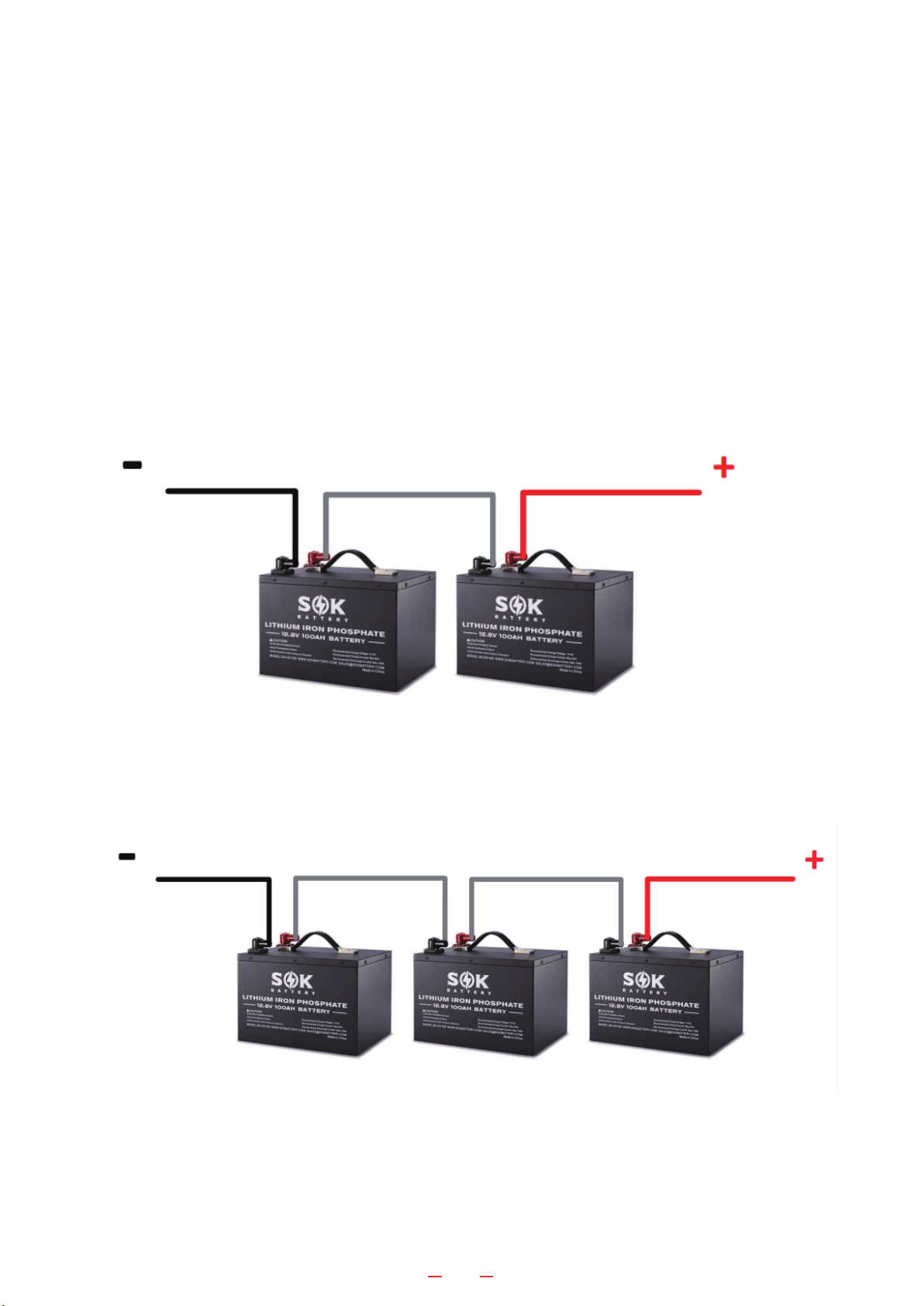
b.36V system connection:
a.24V system connection:
2.1 - Series Connection
Series and Parallel Configurations
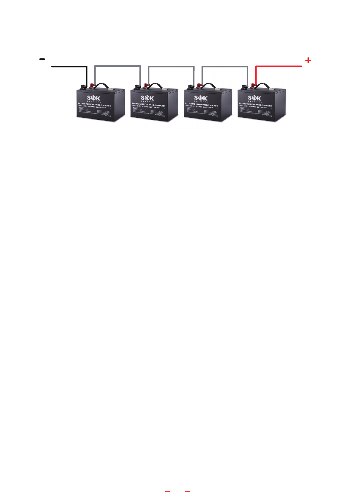
Series: All SOK 12V battery support connecting in series for 24V, 36V, or 48V systems.
DO NOT connect over 4 pcs in series.
Parallel: All SOK 12V, 24V, and 48V batteries support connecting in parallel for more
capacity. It is recommended to not connect over 10 pcs in parallel
2.0 - Installation
sokba�ey.com| Saint Laurent,Quebec H4T 4L2, Canada | Rancho Cucamonga, CA 91739 | sales@sokba�ery.com
※Important points to note when connecting batteries in series
a.Before connecting, individually charge all batteries fully until “C MOS” indicator on the home
page of the app turns off to ensure batteries are at the same SOC.
b.Add a battery voltage balancer. Periodically check to ensure all batteries are the same voltage,
especially when the bank is fully charged.
c. Pre-charge before you turn on inverter. Check this video for details:
https://www.youtube.com/watch?v=ZlrtmJRfSP8&t=68s
c.48V system connection:
01 02 03 04 05
06 07 08 09 10
11 12 13 14 15
16 17
sokba�ey.com| Saint Laurent,Quebec H4T 4L2, Canada | Rancho Cucamonga, CA 91739 | sales@sokba�ery.com
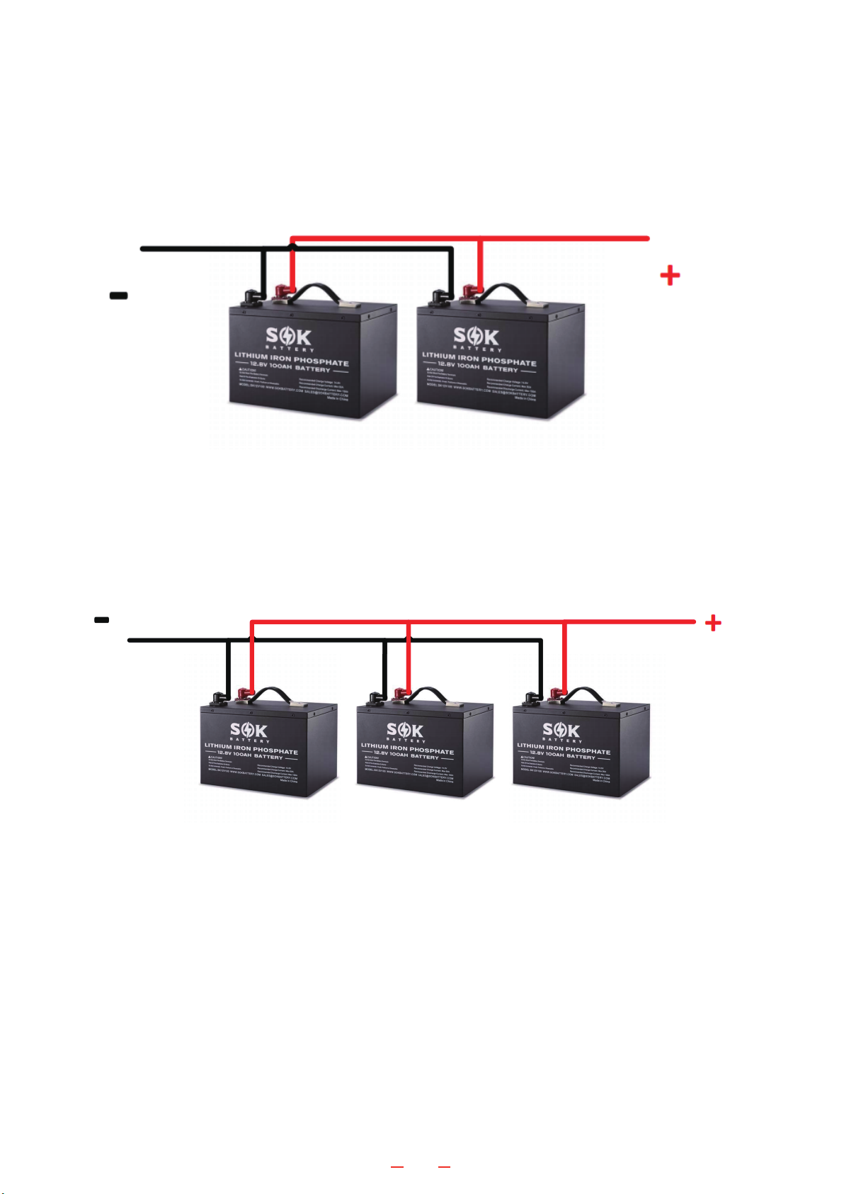
a.Connect 2 batteries
c.Connect 10 batteries
b.Connect 3 batteries
01 02 03 04 05
06 07 08 09 10
11 12 13 14 15
16 17
2.2 - Parallel Connection
sokba�ey.com| Saint Laurent,Quebec H4T 4L2, Canada | Rancho Cucamonga, CA 91739 | sales@sokba�ery.com
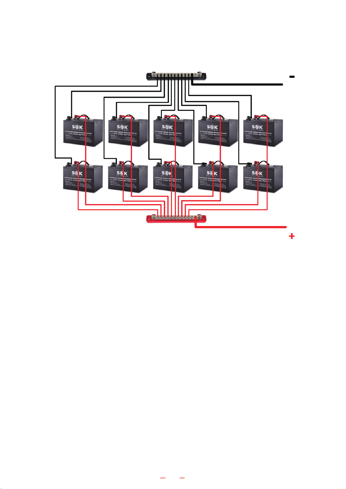
※Important points to note when connecting batteries in parallel
a.Before connecting, individually charge all batteries fully until “C MOS” indicator on the
home page of the app turns off to ensure batteries are at the same SOC.
b.Using the same size and length cables to connect between batteries, the best way is
connect each battery with the same size and length cable to bus bar, and then connect
bus bar to charger or inverter.
c.Connect 10 batteries
01 02 03 04 05
06 07 08 09 10
11 12 13 14 15
16 17
sokba�ey.com| Saint Laurent,Quebec H4T 4L2, Canada | Rancho Cucamonga, CA 91739 | sales@sokba�ery.com

2.3 - Parallel & Series Connection
a.Before connecting, individually charge all batteries fully until “C MOS” indicator on the
home page of the app turns off to ensure batteries are at the same SOC.
b.Add a battery voltage balancer. Periodically check to ensure all batteries are the same
voltage, especially when the bank is fully charged.
c.Ensure the same size and length cable are used for all connections between the batter-
ies.
d.Make the parallel connections first, then make the series connections
For example, to make a 36V 200Ah bank with 6 12V 100Ah batteries:
1.Connect 2 batteries in parallel (1 unit)
2.Make 2 more sets of 2 batteries (2 units)
3.Connect the 3 units in series
01 02 03 04 05
06 07 08 09 10
11 12 13 14 15
16 17
sokba�ey.com| Saint Laurent,Quebec H4T 4L2, Canada | Rancho Cucamonga, CA 91739 | sales@sokba�ery.com

SOK lithium batteries can be charged via several different methods.
3.1 - AC to DC charger
A charger with a charge voltage of 14.4V to 14.6V is required for SOK 12V battery. A charger
with a voltage of 28.8V to 29.2V is required for SOK 24V battery. Most AGM battery chargers
produce charge voltages within that range and would be compatible with SOK lithium batter-
ies .
For example:
●Victron Energy Blue Smart IP65 12-Volt 15 amp Battery Charger (Bluetooth) would be
suitable to charge the SOK 12V battery.
●Victron Energy Blue Smart IP67 24-Volt 12 amp 120VAC Battery Charger (Bluetooth)
would be suitable to charge the SOK 24V battery.
3.2 - Alternator or Generator
Check this video for information about charging batteries using an alternator:
https://www.youtube.com/watch?v=ZyIJRjJtCR0
Check this video for information about charging batteries using a Generator.
https://www.youtube.com/watch?v=QAoorfdbefo
3.3 - Solar
When using solar to charge the batteries, an MPPT Solar Charge Controller is recommended.
How to set up an MTTP Solar Charge Controller:
https://www.us.sokbattery.com/forum/questions-answers/how-to-set-up-an-mttp-solar-char
ge-controller
For a single SOK 12V 100Ah, at least 300W of paneling is recommended.
For a single SOK 12V 206Ah, at least 500W of paneling is recommended.
01 02 03 04 05
06 07 08 09 10
11 12 13 14 15
16 17
3.0 - Suitable Chargers
sokba�ey.com| Saint Laurent,Quebec H4T 4L2, Canada | Rancho Cucamonga, CA 91739 | sales@sokba�ery.com

Figure 4 shows ABC-BMS home page. This page shows basic information about the connect-
ed battery, like voltage, current, individual cell voltage, software version, etc.
If the C MOS slider is green, then charging is enabled. If the slider is gray then charging is
disabled and the BMS is in protection mode.
If the D MOS slider is green, then discharging is enabled. If the slider is gray then discharging
is disabled and the BMS is in protection mode.
If the BMS is in protection mode, the PROT State slider will be green. To view the reason for
the protection state, tap on the Menu icon (··· ) in the top right and select PROT State to
bring up the PROT State page.
01 02 03 04 05
06 07 08 09 10
11 12 13 14 15
16 17
4.0 - Bluetooth App
sokba�ey.com| Saint Laurent,Quebec H4T 4L2, Canada | Rancho Cucamonga, CA 91739 | sales@sokba�ery.com
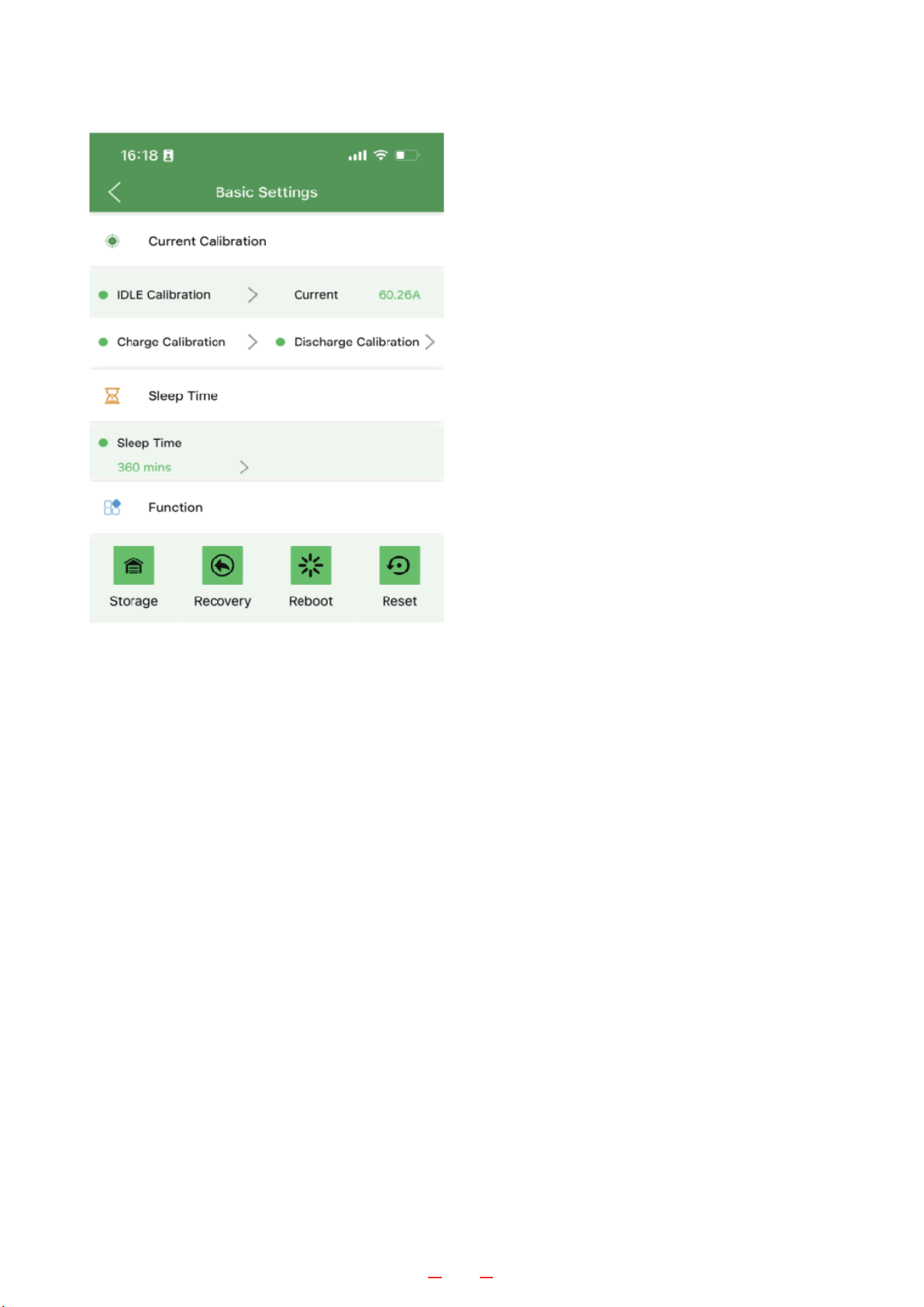
Figure 5 shows the Basic Settings page. To
view this page, tap the menu icon (··· ) in the
top right, select Basic Settings, and use pass-
word 200010.
IDLE Calibration: This function calibrates the
0A point for the BMS. With nothing connected
to the terminals, if the current shows a non 0A
value, please perform an IDLE Calibration by
tapping IDLE Calibration and selecting OK
when prompted
Charge/Discharge Calibration: Factory use
only.
Sleep Time: The value of time of inactivity (no charge or discharge) before the BMS enters
sleep state. In this state, the Bluetooth stops broadcasting to save power. To recover from
sleep, charge or discharge the battery.
Storage: Put the battery in a super low power state to minimize draining when putting the
battery into storage. To recover from storage state, charge the battery with a LiFePO4 char-
ger.
Recovery: Force a recovery from overcurrent protection state. If the BMS shut down from
an overcurrent event and recovery is not possible (e.g. there is no external power for the char-
ger to work), this function would force the BMS to recover from that protection state.
Reboot: Reboot the BMS.
Reset: Reset the parameters to their default values (for customers, this is not necessary as
the parameters are set at the factory and cannot be changed by the customer).
01 02 03 04 05
06 07 08 09 10
11 12 13 14 15
16 17
sokba�ey.com| Saint Laurent,Quebec H4T 4L2, Canada | Rancho Cucamonga, CA 91739 | sales@sokba�ery.com

Figure 6 shows the PROT State page. To view this page, tap the menu icon (··· ) in the top
right, select PROT State. If the PROT State slider on the home page is green, this page will
show the reason for the protection state.
01 02 03 04 05
06 07 08 09 10
11 12 13 14 15
16 17
sokba�ey.com| Saint Laurent,Quebec H4T 4L2, Canada | Rancho Cucamonga, CA 91739 | sales@sokba�ery.com

Cell Overcharged Cell voltage greater than set limit
Total Overcharged Battery voltage greater than set limit
Charging Overcurrent Charge current greater than set limit
Cell Overtemperature Temperature greater than allowable for charging
Cell Low Temperature Temperature less than allowable for charging
MOS Overtemperature BMS temperature greater than set limit during charging
Cell Overdischarged Cell voltage less than set limit
Total Overdischarged Battery voltage less than set limit
Discharging Overcurrent Discharge current greater than set limit
Cell Overtemperature Temperature greater than allowable for discharging
Cell Low Temperature Temperature less than allowable for discharging
MOS Overtemperature BMS temperature greater than set limit during charging
Short Circuit Short circuit detected
Overcurrent Current greater than limit set in hardware
Overdischarged Voltage less than limit set in hardware
Overcharged Voltage greater than limit set in hardware
Charge Protection States (CMOS OFF)
Discharge Protection States (DMOS OFF)
Hardware Protection States
The BMS has 2 steps of protection. The first step is the State of Charge and State of
Discharge, which is called software protection. If the first step doesn’t catch the condition,
then the hardware protection catches it.
01 02 03 04 05
06 07 08 09 10
11 12 13 14 15
16 17
sokba�ey.com| Saint Laurent,Quebec H4T 4L2, Canada | Rancho Cucamonga, CA 91739 | sales@sokba�ery.com

The built-in heat pad turns on under the following conditions:
●Temperature is below 0° C (32°F)
●A charger is connected and able to supply sufficient current to the pads
◦≥ 4A for each 100Ah battery
◦≥ 7A for each 206Ah battery
For example, on a cold evening after the temperature drops down to under 0°C (32°F), when
charging the heated battery, the battery would go into low temperature protection. Charging
the cells is disabled, and if the charger is able to supply a sufficient amount of current, the
heat pad would automatically turn on. When the battery temperature exceeds 5°C (41°F), the
heat pad turns off, and charging the cells is re-enabled.
Storage
●Charge the battery to 13.5V – 13.6V
●Turn off everything or completely disconnect the batteries
Note: Low temperature would not damage the battery’s cells.
01 02 03 04 05
06 07 08 09 10
11 12 13 14 15
16 17
5.0 - Built-in Heat Pad Functionality
sokba�ey.com| Saint Laurent,Quebec H4T 4L2, Canada | Rancho Cucamonga, CA 91739 | sales@sokba�ery.com

Battery voltage 0V at terminals
BMS in protection state, or internal voltage too low for BMS to function. Charging the battery
should fix this. Please see these 2 videos:
How To Wake Up A Sleeping LiFePO4 Battery
https://www.youtube.com/watch?v=TJ_Klwp-JyM
https://www.us.sokbattery.com/forum/questions-answers/how-to-set-up-an-mttp-solar-char
ge-controller
Terminology
BMS
Battery Management System: a device in the battery
that protects the cells.
SOC State Of Charge
CMOS
Charge MOS: transistors that allow charging. When
gray, charging is disabled
DMOS
Discharge MOS: transistors that allow discharging.
When gray, discharging is disabled
LiFePO4 Lithium Iron Phosphate
MPPT
Maximum Power Point Tracking – technique that
allows for maximum power extraction from variable
power sources (for example, solar or wind charging)
01 02 03 04 05
06 07 08 09 10
11 12 13 14 15
16 17
6.0 - Troubleshooting
sokba�ey.com| Saint Laurent,Quebec H4T 4L2, Canada | Rancho Cucamonga, CA 91739 | sales@sokba�ery.com
This manual suits for next models
7
Table of contents
Popular Batteries Pack manuals by other brands

Cooper Lighting Solutions
Cooper Lighting Solutions Metalux CBRK installation instructions

EGO
EGO BACKPACK LINK BH1001-FC Operator's manual

Gerbing
Gerbing A60 manual

POWEROLOGY
POWEROLOGY PPBCHA2681 manual

Sony
Sony BP-IL75 Operation manual

Treasure Garden
Treasure Garden P-AKZPBATTERY Assembly and operation guide


