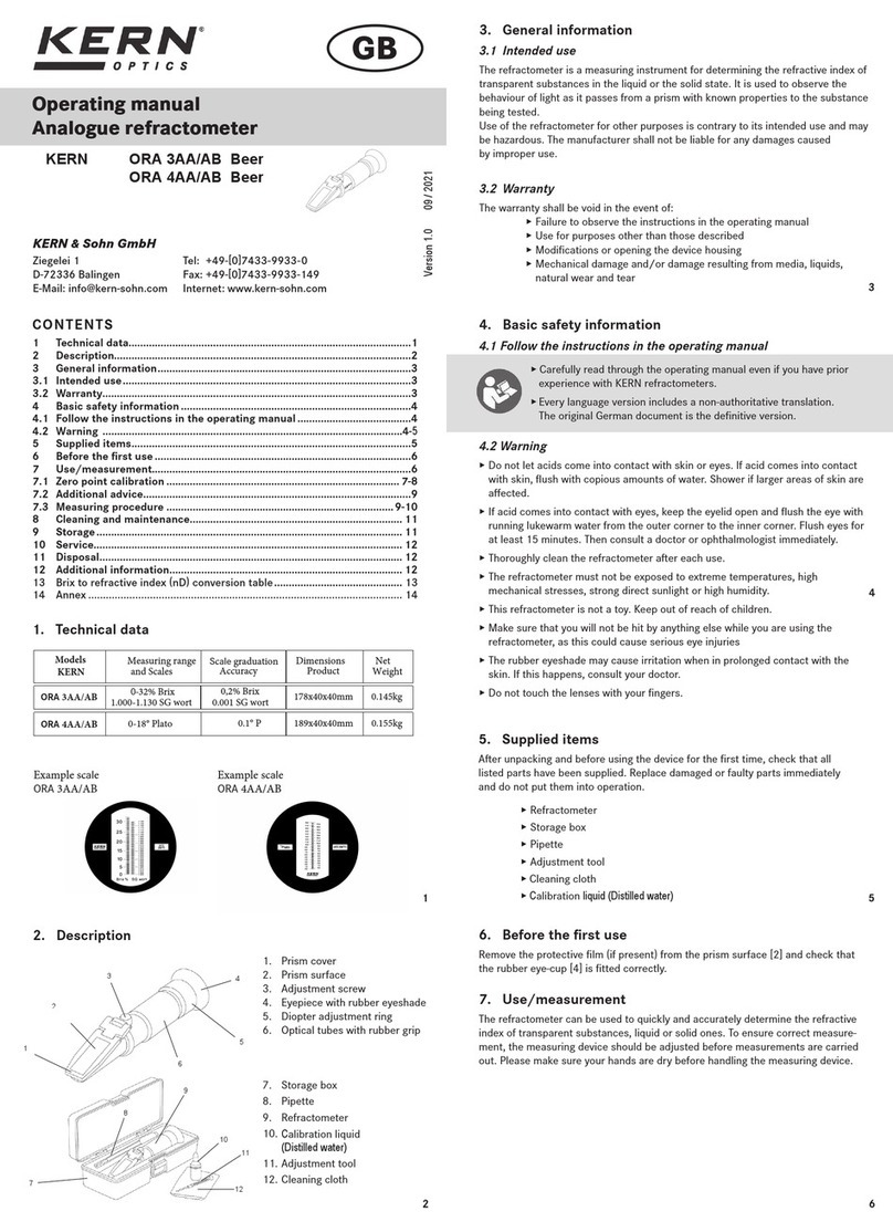
AESSEAL FLOWTRUE FTP-50-145 Instruction manual

YDR-FLOWTRUE-HF-01 01/2021
FLOWTRUE™ High Flow
High Flow Model FTP-50-145 / FTP-50-360
Installation Operations & Maintenance Instructions

YDR-FLOWTRUE-HF-01 01/2021
AESSEAL (MCK) Ltd. 139A Hillsborough Old Road, Lisburn, N.Ireland, BT27 5QE
Tel: +44 (0) 28 9266 9966 Fax: +44 (0) 28 9266 9977 Email: MCK@aesseal.co.uk www.aesseal.com
Page 2 of 6
Health and Safety
• Before attempting work on any process equipment, ensure that all permit requirements are satisfied and all
necessary process, electrical and mechanical isolations are in place.
• The system should be installed by competent engineering personnel.
• Do not over-pressurise the FLOWTRUE™ beyond the maximum design pressure. If there is any possibility of
over-pressurisation the system must be fitted with a suitable protection device – contact AESSEAL®for
advice.
• Do not exceed the operating limits of the FLOWTRUE™.
• Ensure the FLOWTRUE™ is completely leak free before full operation.
•
The FLOWTRUE™ device has been designed for use
only as a
regulated flow meter for gland packing sealing
arrangements and single mechanical seals.
•
If there is a chance of high reverse pressure which could contaminate the water supply, we recommend the
use of a non-return valve in the supply line to the Flowtrue™.
Environment
Once the device has reached the end of its serviceable life, it should be disposed of in accordance with local regulations and
with due regard to the environment.
For further information please contact AESSEAL®

YDR-FLOWTRUE-HF-01 01/2021
AESSEAL (MCK) Ltd. 139A Hillsborough Old Road, Lisburn, N.Ireland, BT27 5QE
Tel: +44 (0) 28 9266 9966 Fax: +44 (0) 28 9266 9977 Email: MCK@aesseal.co.uk www.aesseal.com
Page 3 of 6
Installing & Commissioning
FIG.1 FLOWTRUE™ Labelled
Components
A= Cleaning Button
B= Inductive Alarm (option – not shown fitted)
C= Target flow indicator
D= Flow indicator ring
E = Cleaning ring
F= Flow indicator adjustment point
H= Flow adjustment valve
I= Plant water supply connection
J= Supply connection to the mechanical seal / stuffing box
K= Pressure gauge
L= Target pressure indicator
Installation & Commissioning
1. New or renewed plant water lines need to be flushed correctly to prevent harmful particles from passing
through the FLOWTRUE™ valve and seal.
Ensure that the plant water supply is closed for stages 2 – 4
2. Install the FLOWTRUE™ in a suitable location which is free from vibration and in close proximity to the pump.
The meter should be mounted so that it is easy to read and maintain. Support stands and brackets are
available on request.
3. Connect the hoses from the plant water supply to the FLOWTRUE™ (I) and from the FLOWTRUE™
connection (J) to the packing flush port or mechanical seal flush.
4. Ensure that the flow valve (H) is closed. This can be done by releasing the locking nut and using the 2.5mm
Allen key supplied, screw the flow valve clockwise until fully closed.
5. Set the red target flow indicator (C) to the desired flow rate using the 2.5mm Allen key supplied.
Turn clockwise to achieve larger target flow rate and anti-clockwise for lower target flow rate.
6. Switch on the plant water supply. Open the flow valve (H) until the white left-hand ring (D) is in line with the
red flow indicator (C).
7. Once the flow is set, secure valve (H) into position by tightening the locking nut.
8. Set the target pressure indicator (L) on the pressure gauge (K) to the desired target pressure.
9. Upon start-up of the equipment, adjustments may need to be made to suit the running conditions.

YDR-FLOWTRUE-HF-01 01/2021
AESSEAL (MCK) Ltd. 139A Hillsborough Old Road, Lisburn, N.Ireland, BT27 5QE
Tel: +44 (0) 28 9266 9966 Fax: +44 (0) 28 9266 9977 Email: MCK@aesseal.co.uk www.aesseal.com
Page 4 of 6
Alarm Option (if selected)
• Remove the alarm label from the top of the FLOWTRUE device and attached the alarm using the screws
supplied.
• Attached the alarm cables to a suitable control panel.
• Using the FLOWTRUE Allen key (G), adjust the flow control value (H) until the flow indicator ring (D) is at the
minimum flow rate acceptable for the application. This will be known as
flow alarm valve.
• Loosen the screws and move the alarm to the far left of the alarm slot. Then, move the alarm to the right until
the light on the alarm comes on.
• When the light comes on, tighten the alarm in position using the screws supplied.
• Using the FLOWTRUE Allen key, adjust the target flow indicator (C) (red marker) to the desired flow for the
application.
• Using the FLOWTRUE Allen key, adjust the flow control valve (H) until the flow indicator ring (D) is in line with
the target flow indicator (C) (red marker).
• The alarm light will remain on until the flow drops below the
flow alarm valve
. This will trigger the selected
alarm device on the control panel.
Technical Data for Alarm Sensor
Hermetically sealed, inductive alarm switch
• Metal or plastic thread 12x1
• Sensing range is 4mm
Electrical design
connection
DC PNP
DC NPN
DC quadronorm
AC
Normal sensing range
4mm
Output
closed
opened
closed
Operating voltage
DC 10-36V
DC 10-55V
AC 20-250V
Current rating,
continuous
250mA
400mA
250mA
Current rating, peak
250mA
400mA
0.9A
(20ms/0.05Hz)
Minimum load current
-
4mA
8mA
Voltage drop
<2.5V
<4.6V
<8.5V
Leakage current
-
<0.5 mA
<3mA(AC 250V)
<1.5mA(AC120V)
Switching frequency
400Hz
1500Hz
25Hz
Output status indication
yellow
Operating temperature
-25oC ~ 80oC
Protection
EMC
IP67
Group 1
IP67
Group 2
Housing Material
Plastic, nickel
Plated brass, or stainless steel.
Connection Cable
PVC
2m/3x0.34mm
PPU
2m/2x0.34mm
PVC
2m/2x0.5mm
Wires:
BN
= brown
BU
= blue
BK
= black
WH
= white

YDR-FLOWTRUE-HF-01 01/2021
AESSEAL (MCK) Ltd. 139A Hillsborough Old Road, Lisburn, N.Ireland, BT27 5QE
Tel: +44 (0) 28 9266 9966 Fax: +44 (0) 28 9266 9977 Email: MCK@aesseal.co.uk www.aesseal.com
Page 5 of 6
Cleaning Operation
1) Unscrew cleaning button (A) by rotating it anti-clockwise.
2) Pull the cleaning button out of the main body. Push the button back and forth until the cleaning ring (E) clears the
flow tube.
3) Push the cleaning button (A) back into the main body and tighten by rotating it clockwise until hand tight.
Note:
During the cleaning process the flow and pressure will not change, In addition the alarm will not activate
Installation Dimensions
Stand
Bracket
Overall outside dimensions (W x D x H)
With mounting bracket:
292x101x142mm(11.5x4”x5.6”) without alarm
292x101x243mm(11.5”x4”x9.6”) with alarm
For models using a floor stand:
292x101x838mm(11.5”x4’x33”) without alarm
292x101x939mm(11.5”x4”x37”) with alarm
726 mm (30”)
80x80 mm (3.1”x3.1”)
66 mm (2.6”)
25 mm (1”)

YDR-FLOWTRUE-HF-01 01/2021
AESSEAL (MCK) Ltd. 139A Hillsborough Old Road, Lisburn, N.Ireland, BT27 5QE
Tel: +44 (0) 28 9266 9966 Fax: +44 (0) 28 9266 9977 Email: MCK@aesseal.co.uk www.aesseal.com
Page 6 of 6
Troubleshooting
Operating Limits:
Polyacetal (standard body material, white in colour)
● Maximum Pressure = 25 bar / 360 psi
● Maximum Temperature = 80°C / 176°F
Polyethylene (chemical environments body material, yellow in colour)
● Maximum Pressure = 10 bar / 145 psi
● Maximum Temperature = 60°C / 140°F
Sr. No
Problem
Corrective action
1.
Welding deposits or other impurities in the meter after
start up.
Flush the sealing water lines well before start up.
2.
Dirty flow tube.
Use flow tube cleaning button monthly.
3.
False alarms due to pressure changes in the sealing
water line.
Set the alarms to lower acceptable flow rate. Correct the seal
water pressure.
4.
Alarm does not trigger.
Check that you have connected the load as indicated in the
wiring diagram. Alarm sensor should rest directly on the flow
tube.
5.
No flow through the meter although the flow adjusting
valve is open.
Check that the pressure adjusting valve is open.
6.
The meter will not deliver the required flow rate.
Check that pressure in the sealing water line is adequate. In
case of new tight packing the flow may also remain small.
7.
Low Flow and High Pressure
The mechanical seal is plugged/blocked or the packing is
potentially too tight
8.
High Flow and Low Pressure
The packing is worn or the mechanical seal is leaking
9.
Low Flow and Low Pressure
Problems with the gland water supply
This manual suits for next models
1
Table of contents


