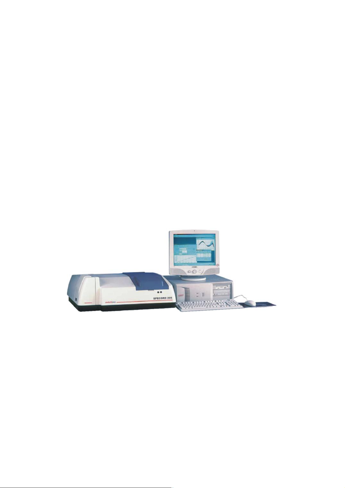
Analytik Jena SPECORD 200 PC User manual

UV VIS Spektralphotometer
SPECORD
200 PC
SPECORD
205 PC
SPECORD
210 PC
Operating Manual
Analytik Jena AG

Analytik Jena AG
Kundendienst
Konrad-Zuse-Str. 1
07745 Jena
Telefon: Hotline: + 49 (3641) 77-7401
Fax: + 49 (3641) 77-7449
E-Mail: service@analytik-jena.de
General information about Analytik Jena AG on the
internet: http://www.analytik-jena.de
Copyrights and Trademarks
Microsoft, Windows 98, Windows NT, MS Word, MS Excel are registered trademarks of
Microsoft Corp.
Publication No.: 221:416.23
Edition – March 2003
Technical documentation made by:
Analytik Jena AG
This documentation describes the state of this product at the
time of publishing. It need not necessarily agree with future
versions of the product.
Subject to change!
© Copyright 2003 Analytik Jena AG

SPECORD®Contents
SPECORD® 200/205/210 User's Manual – Edition 03/2003 Page 1
Analytik Jena AG
Contents
1Introduction 3
1.1 Conventions............................................................................................................. 3
1.2 Intended use of the SPECORD®.............................................................................. 4
2Safety notes 5
3Disposal 9
4Technical data of the spectrophotometers 11
4.1 Optical data of SPECORD®.................................................................................... 11
4.2 General technical data of SPECORD®................................................................... 12
5Device description and operating principle 13
5.1 Mechanical design of SPECORD®......................................................................... 13
5.2 Design of subassemblies ....................................................................................... 15
5.2.1 Light sources ......................................................................................................... 15
5.2.2 Spectrometer system and photometer section ....................................................... 16
5.2.3 Sample compartment............................................................................................. 17
6Installation requirements 21
7Installation and start-up 23
7.1 Connectors and display elements .......................................................................... 23
7.2 Removing the transport lock................................................................................... 25
7.3 Connecting the SPECORD®................................................................................... 26
7.4 Start-up.................................................................................................................. 28
7.5 Switching the device off ......................................................................................... 30
7.5.1 Switching the deuterium lamp off ........................................................................... 30
7.5.2 Switching the SPECORD®off ................................................................................ 30
8Accessories 31
8.1 Standard cell holders ............................................................................................. 31
8.2 Receptacle for cells with turbid samples................................................................. 32
8.3 Additional accessories ........................................................................................... 33
9Care, maintenance, lamp change 35
9.1 Care and maintenance........................................................................................... 35
9.2 Cleaning................................................................................................................. 35
9.3 Changing lamps..................................................................................................... 36
9.3.1 Note on the service life of lamps ............................................................................ 36
9.3.2 Opening the flap of the lamp compartment............................................................. 36
9.3.3 Changing the deuterium lamp ................................................................................ 38
9.3.4 Changing the halogen lamp ................................................................................... 41

Contents SPECORD®
Page 2 SPECORD®200/205/210 User's Manual – Edition 03/2003
Analytik Jena AG
9.4 Changing the desiccator ........................................................................................ 43
9.5 Changing fuses...................................................................................................... 44
10 Index to Illustrations 45
11 Index to Overviews 45

SPECORD®Introduction
Conventions
SPECORD® 200/205/210 User's Manual – Edition 03/2003 Page 3
Analytik Jena AG
1 Introduction
1.1 Conventions
This manual contains the description of the following devices
• SPECORD®200
• SPECORD®205
• SPECORD®210
If the descriptions equally refer to all three models, only the collective term
SPECORD®will be used. If a property of an individual model shall be particularly
stressed, the full name of the model will be mentioned.
In this manual, the following symbols are used to refer you to warnings and notes:
Warning!
Warning messages alert you to a specific procedure or practice which, if not
followed correctly, could cause personal injury.
Caution!
Caution messages refer you to procedures which, if not observed, could
result in damage to the equipment.
Dangerous electric voltage!
Emission of UV radiation!
Disconnect power cable!
Note
This note must be followed to obtain correct measurement results.
For easier navigation within the manual, the manual uses the following system:
• Chapters and illustrations are numbered consecutively.
• Every illustration has its own caption.
■This symbol denotes a step of operation.

Introduction SPECORD®
Intended use of the SPECORD®
Page 4 SPECORD®200/205/210 User's Manual – Edition 03/2003
Analytik Jena AG
□This symbol denotes a step of operation being alternative to the
previously described and having the same effect or leading to a follow-up
step of a branching step of operation.
→Cross-reference: Refers to another section/illustration of the manual.
1.2 Intended use of the SPECORD®
The SPECORD®is a powerful, computer-controlled double-beam spectrophoto-
meter for the measurement of the transmission, absorbance, reflection as well as
the energy of liquid and solid samples. It is designed for measurements in the
spectral range 190 – 1100 nm.
The double-beam spectrophotometers of the SPECORD®family provide different
spectral resolutions:
SPECORD®200 1; 2 and 4 nm
SPECORD®205 1.4 nm
SPECORD®210 0.5, 1, 2 and 4 nm
The optical system without electromechanical modulator ensures true real-time
operation, so that even variations in the absorbance of references can be
compensated during the measurement.
The internal wavelength calibration with a holmium oxide filter provides a high
wavelength accuracy and reproducibility.
The SPECORD®complies with the regulations of the DAB (German
Pharmacopoeia) and international regulations, such as PhEur., BP, USP or JPXIII.
In combination with the powerful WinASPECT®software, the SPECORD®is
particularly suitable for the use in routine laboratories with a high sample throughput,
but also provides solutions for special applications, if used in combination with the
diverse accessories available.

SPECORD®Safety notes
SPECORD® 200/205/210 User's Manual – Edition 03/2003 Page 5
Analytik Jena AG
2 Safety notes
For your personal safety and for a trouble-free operation, carefully read this chapter
before starting up the SPECORD®.
Observe all safety notes given in this manual and all messages and notes displayed
by the control software on the screen.
In addition, observe the safety notes for system components of other manufacturers
(e.g. PC, printer, autosampler) supplied together with the device.
In particular, you should also observe the safety notes given on the labels and the
information on the use, storage and disposal of reagents, reaction cells and the
notes on the package inserts of test kits.
Intended use!
The SPECORD®, including original accessories, may only be used for the
applications described in this manual. The manufacturer cannot assume any liability
for any other application, including that of individual modules or single parts. This
also applies to all service or repair work that is not carried out by authorized service
personnel. All warranty claims shall be forfeited.
Local safety regulations!
Observe the local safety regulations relevant to the operation of the device (e.g.
labor-safety regulations, regulations for the prevention of and protection against
accidents).
References to possible risks given in this manual do not replace the relevant labor-
safety regulations that are to be followed.
Personnel!
The SPECORD®may only be operated by appropriately qualified and trained
personnel.
For that, the knowledge of the information provided by this manual is indispensable
and taken for granted.
Emergency stop!
In the case of emergency, disconnect the SPECORD®and its components from line
power by removing the power plug from the power outlet.

Safety notes SPECORD®
Page 6 SPECORD®200/205/210 User's Manual – Edition 03/2003
Analytik Jena AG
Electric shocks!
The SPECORD®is electrically powered. At several parts inside the system,
extremely hazardous electrical voltages are accessible!
To ensure Protection Class I (protective earth connection) of the device, connect the
power plug of the device only to a power outlet with protective earth conductor. The
protective effect must not be undone by the use of an extension cable without
protective earth conductor.
Before opening the device or removing any device covers, disconnect the power
cable!
Before connecting the SPECORD®to the power outlet, make sure the line voltage
supplied agrees with the operating voltage specified on the rating plate at the rear
panel of the device. Operation of the device with any other operating voltage than
that specified may result in the destruction of the device.
Only use fuses of the specified type.
Do not operate the device in explosion-risk rooms!
UV radiation!
Never look directly or indirectly, e.g. via a mirror, into the radiation emitted by the
lamp to avoid the risk of getting conjunctivitis!
Therefore, switch off the lamp for lamp replacement!
Lamp damage!
Do not grasp functioning halogen and deuterium lamps on their glass bulbs.
Contamination on the bulb affects the radiation properties of the lamps.
Especially protect the beam-exit window of the deuterium lamp.
Make sure to remove the protective cap from the halogen bulb after having inserted
it to avoid any risk of fire!
Non-observance will result in damage of the lamp.
Accumulation of heat
Heat accumulation might result in overheating and faults on the device.
Make sure not to cover the ventilation slots of the SPECORD®!
Before you switch on the SPECORD®, remove its dust cover!

SPECORD®Safety notes
SPECORD® 200/205/210 User's Manual – Edition 03/2003 Page 7
Analytik Jena AG
Handling liquids
Take care to ensure that no liquids can enter the SPECORD®to avoid any damage
to the device.
Risk of corrosion
Do not set up the device in the vicinity of aggressive vapors, e.g. strongly corrosive
acid or caustic vapors! The vapors might corrode the connections, mechanical and
optical components of the device.
Avoid exposing the sample compartment to strongly corrosive substances! For the
analysis of such samples, use vapor-tight stoppered cells.
After the measurement, do not leave the samples unnecessarily long in the sample
compartment of the device!
The SPECORD®was produced and tested in compliance with the following
standards and regulations:
• DIN EN 61010-1 (IEC 1010-1)
• 73/23/EC
• 89/336/EC.
The SPECORD®meets the requirements as per Protection Type IP 20.

Safety notes SPECORD®
Page 8 SPECORD®200/205/210 User's Manual – Edition 03/2003
Analytik Jena AG

SPECORD®Disposal
SPECORD® 200/205/210 User's Manual – Edition 03/2003 Page 9
Analytik Jena AG
3 Disposal
The owner/operator of the SPECORD®must ensure to dispose of the waste material
(samples) cropping up in the analyses in accordance with the relevant legal and
local regulations.
When the service life of the device is over, dispose of the device with its electronic
components as electronic scrap observing the relevant regulations.
You can also return the SPECORD®to Analytik Jena AG for disposal. Please
contact our Technical Service.

Disposal SPECORD®
Page 10 SPECORD®200/205/210 User's Manual – Edition 03/2003
Analytik Jena AG

SPECORD®Technical data of the spectrophotometers
Optical data of SPECORD®
SPECORD® 200/205/210 User's Manual – Edition 03/2003 Page 11
Analytik Jena AG
4 Technical data of the spectrophotometers
4.1 Optical data of SPECORD®
SPECORD®200 / 205 / 210
Principle Double-beam spectrophotometer with two large-
area Peltier temperature-controlled photodiodes
Optics Monochromator with holographic concave grating
Light split into two beams by a beam-splitting plate
Light sources Deuterium lamp and halogen lamp,
pre-aligned
Wavelength range 190 ... 1100 nm
Photometric range - 3 ... + 3 A
Wavelength accuracy ± 0.5 nm at 360,9 nm with holmium glass filter*
Wavelength reproducibility ± 0.1 nm (5 measurements)
Stray light < 0.5 % T at 200 nm (KCl)*
< 0.05 % T at 220 nm (NaJ, ASTM) *
< 0.05 % T at 340 nm (NaNO2, ASTM) *
Photometric accuracy VIS ± 0.005 A at A = 1
Photometric accuracy UV ± 0.005 A at A = 1; potassium dichromate
Photometric reproducibility ± 0.0005 A/h at A = 1
Long term stability ± 0.001 A/h at 500 nm (1 h warm-up)
Baseline stability ± 0.001 A from 200 to 800 nm with slit 2 nm
Zero-line of transmission ± 0.03 %T
RMS noise ± 0.0001
Scanning speed 30, 60, 120, 300, 600, 1200, 3000, 6000 nm/min
*)allowing for tolerances of used standard
SPECORD®200 SPECORD®205 SPECORD®210
Spectral bandwith 1 / 2 / 4 nm, variable 1.4 nm 0.5 / 1 / 2 / 4 nm,
variable
Toluene / hexan
resolution
> 2.1 > 1.7 > 2.1
Overview 4-1 Technical data of SPECORD®200

Technical data of the spectrophotometers SPECORD®
General technical data of SPECORD®
Page 12 SPECORD®200/205/210 User's Manual – Edition 03/2003
Analytik Jena AG
4.2 General technical data of SPECORD®
Weight 18 kg
Footprint (W x D) approx. 1200 x 750 mm2with PC
Dimensions (W x H x D) 680 x 240 x 620 mm3
Line voltage 230 VAC ±10 % and switchable to
115 VAC ±10 % (by Technical Service)
Line frequency 47 ... 63 Hz
Power consumption 195 VA
Fuses:
Line fuses
230 VAC: T 3.15 AH/250V, Type 19181
(Wickmann)
115 VAC: T 3,15 AH/250V, Type19181
(Wickmann)
Radio noise suppression as per EN 55011 Class A
Noise immunity as per DIN EN 50082-1
Protection Type IP 20
Data interface RS-232 port
PC requirements for software:
Aspect Plus and WinASPECT
MS Windows 2000 operating system or higher
Overview 4-2 General technical data of SPECORD®

SPECORD®Device description and operating principle
Mechanical design of SPECORD®
SPECORD® 200/205/210 User's Manual – Edition 03/2003 Page 13
Analytik Jena AG
5 Device description and operating principle
5.1 Mechanical design of SPECORD®
Fig. 5-1 Mechanical design of SPECORD®
1 Light sources 6 Detector board
2 Desiccator 7 Holder for turbid samples
3 Cover of spectrometer system and photometer section 8 Support plate
4 Device control 9 Holder for cells
5 Power supply module 10 Sample compartment
The major subassemblies of the SPECORD®are:
Light sources (1) Halogen lamp and deuterium lamp generate the light that
is monochromatized in the spectrometer system. Then, it
passes through the sample.
Spectrometer
system
The spectrometer system is protected against
extraneous light and dust by cover (3). The desiccator (2)
regulates the humidity inside the system.

Device description and operating principle SPECORD®
Mechanical design of SPECORD®
Page 14 SPECORD®200/205/210 User's Manual – Edition 03/2003
Analytik Jena AG
Photometer section This subassembly serves to split the light exiting the
monochromator into sample and reference beam. The
optical system shapes the beam cross-section in the
sample compartment. The photometer section, too, is
protected by cover (3).
Sample
compartment (10)
The sample compartment contains two pairs of carrier
rods for the accommodation of various accessory units.
To the support plate (8), two holders for the
accommodation of cells (9) and the detector board are
mounted.
Detector board (6) Two photodiodes are used as radiation detectors, which
on the SPECORD®200/210 are Peltier temperature-
controlled.
Power supply
module (5)
The power supply modules supply the electrical voltage
to the electronic system and the fans for the
thermoelectric temperature control of the detectors on
the SPECORD®200/210.
Device control
computer (4)
The device control computer coordinates the interaction
of the subassemblies involved in the measurement
processes.

SPECORD®Device description and operating principle
Design of subassemblies
SPECORD® 200/205/210 User's Manual – Edition 03/2003 Page 15
Analytik Jena AG
5.2 Design of subassemblies
5.2.1 Light sources
Fig. 5-2 Lamp compartment (without cover)
1 Halogen lamp in protective housing 4 Toric illuminating mirror
2 D2E lamp compartment 5 Setscrew for mirror adjustment
3 Reflecting mirror
The light sources used are a deuterium lamp (2) for the UV region and a halogen
lamp (1) for the VIS region of the spectrum.
Depending on the position of reflecting mirror (3), which is mounted onto a moving
magnet, the radiation of either deuterium or halogen lamp is sent onto the entrance
slit of the monochromator. You can choose the wavelength at which the lamp is
changed over a wide range using the WinASPECT®control and analysis software.
The toric mirror (4) serves for imaging the light sources onto the entrance slit of the
monochromator. To obtain the maximum possible energy of the deuterium lamp for
the measurement, you can sensitively adjust the setscrew for mirror adjustment (5).

Device description and operating principle SPECORD®
Design of subassemblies
Page 16 SPECORD®200/205/210 User's Manual – Edition 03/2003
Analytik Jena AG
5.2.2 Spectrometer system and photometer section
S
PE
CO
RD 200 –
O
ptical Diagram
Sample compartment
Concave grating
Filter wheel
Plane mirror
Beam splitter
Quartz-coated
toric mirrors
Entrance
slit
Exit
slit
DElamp
2
Halogen lamp
Swivel mirror
Detector
Cavity for
turbid samples
Sample cell
Reference cell
Fig. 5-3 Schematic setup – Optical diagram of SPECORD®
The spectrometer system with the optical elements illustrated above – filter wheel,
concave grating and slit assembly – works as monochromator.
The filter wheel contains the following filters:
4 color glass filters Used to suppress unwanted radiation in the
monochromator.
Holmium filter Standard for the automatic recalibration of wavelengths.
2 blank positions
Block position Needed for the generation of measured data.
The entrance and exit slits of the spectrometer system are mounted to the slit
carrier. Depending on the device model, the slits allow the following spectral slit
widths:
SPECORD®200 1, 2, 4 nm
SPECORD®205 1.4 nm
SPECORD®210 0.5, 1, 2, 4 nm.
The imaging grating disperses the incident light and spreads it out into a spectrum.

SPECORD®Device description and operating principle
Design of subassemblies
SPECORD® 200/205/210 User's Manual – Edition 03/2003 Page 17
Analytik Jena AG
Computer-controlled stepper motors drive the filter wheel, the slit carrier and the
linear actuator for moving the grating. Because of the little number of moving parts
used in the spectrometer system, the SPECORD®ensures a high reliability of its
optical parameters.
In the photometer section, the mirror system divides the beam coming from the
monochromator into sample and reference beam. The imaging mirrors shape the
beam to the cross-sections needed in the sample compartment.
Spectrometer system and photometer section are protected against dust and
reagents by a cover. However, corrosive reagents or strongly evaporating liquids
should be inserted in the sample compartment only in stoppered cells.
5.2.3 Sample compartment
1
2
3
45
6
7
8
9
1
0
11
Fig. 5-4 Sample compartment
1 Sample beam path with 2 carrier rods 7 Mount for cell holder
2 Reference beam path with 2 carrier rods 8 Receptacle for cells with turbid samples
3 Connector for sipper and cell changer 9 Mount for cell holder
4 Reserve connector 10 Conduit for sample drain hose
5 Stopper for optical fiber of measuring probe 11 Conduits for sample-aspirating hoses (sipper)
6 Conduits for coolant hoses

Device description and operating principle SPECORD®
Design of subassemblies
Page 18 SPECORD®200/205/210 User's Manual – Edition 03/2003
Analytik Jena AG
Sample (1) and reference beam (2) enter the sample compartment through the left-
hand wall.
The mounts for the cell holders (7),(8) are arranged in front of the exit windows in the
right-hand sample compartment wall.
The two pairs of carrier rods serve to accommodate the universal holder and other
accessories, which easily clamp to the rods.
The receptacles for the cells (8) with turbid samples are located directly in front of the
detector at the right-hand sample-compartment wall.
Two 9-pin connectors (3), (4) allow the connection of electrically driven accessories,
such as the automatic temperature-controlled cell changer or the sipper system.
The optical fibers of the measuring probe or the cables of the Peltier temperature-
controlled cell holder or the cell changer are threaded through the recess in the rear
wall of the sample compartment (5).
The three conduits (6,11) in the right-hand sample compartment wall are used for
threading through the sample drain hose and two coolant hoses for the thermostat.
Two openings in the front of the device cover are provided for the aspiration tubes of
the super sipper system.
The illustration below shows the geometrical dimensions of the sample
compartment.
This manual suits for next models
2
Table of contents
Other Analytik Jena Measuring Instrument manuals

Analytik Jena
Analytik Jena multi EA 4000 User manual

Analytik Jena
Analytik Jena SPECORD S600 User manual

Analytik Jena
Analytik Jena compEAct S User manual

Analytik Jena
Analytik Jena SPECORD S600 User manual

Analytik Jena
Analytik Jena SPECORD 200 User manual

Analytik Jena
Analytik Jena SPECORD S600 User manual

Analytik Jena
Analytik Jena compEAct N User manual

Analytik Jena
Analytik Jena SPEKOL 1500 User manual

Analytik Jena
Analytik Jena SPEKOL 1300 User manual

Analytik Jena
Analytik Jena SPECORD 50 PLUS User manual