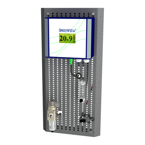
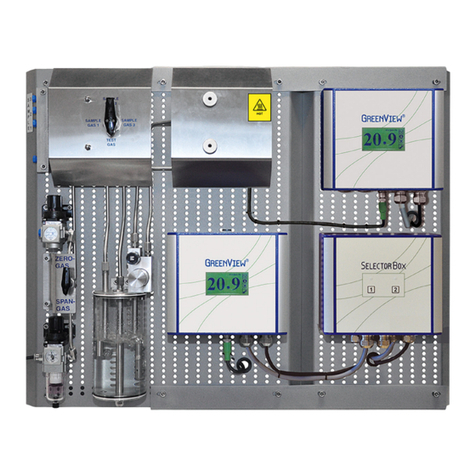
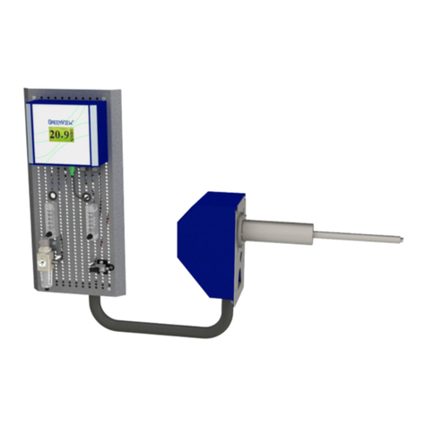
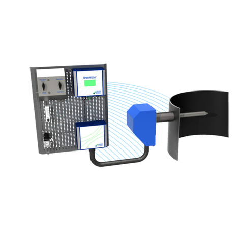
GREEN INSTRUMENTS Maritime G6100 User manual

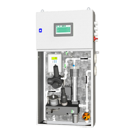
G6100
Water Monitoring
System
Operation Manual
Document ID number.: 02480
Maritime

Program Menu Structure
Page 2 of 111
Figure 1-1: Program Menu Structure of the Water Monitoring System

Water Monitoring System
Ver.5.0.1 – Revision August 2022Page 3 of 111
Content
1INTRODUCTION ...........................................................................................................................7
1.1 ABOUT THIS MANUAL ..................................................................................................................... 7
1.2 INQUIRIES AND FEEDBACK .............................................................................................................. 8
1.3 ABOUT THE SYSTEM ...................................................................................................................... 8
2SPECIFICATIONS...................................................................................................................... 10
3SAFETY ASPECTS.................................................................................................................... 15
4MENU STRUCTURE .................................................................................................................. 18
4.1 HOME ........................................................................................................................................ 18
4.1.1 PAH ............................................................................................................................ 19
4.1.2 Turbidity, pH/Temperature or Flow ............................................................................. 21
4.2 SETTINGS ................................................................................................................................... 22
4.2.1 Setup.......................................................................................................................... 22
4.2.2 Alarms ........................................................................................................................ 25
4.2.3 External Communication Watchdog ........................................................................... 25
4.2.4 Logging ...................................................................................................................... 26
4.2.5 IP Address Configuration............................................................................................ 26
4.2.6 Software Update ........................................................................................................ 27
4.3 TREND SELECTION ...................................................................................................................... 29
4.3.1 Trend Graph ............................................................................................................... 29
4.4 RUN........................................................................................................................................... 29
5COMMISSIONING...................................................................................................................... 30
5.1 WM ........................................................................................................................................... 30
5.2 WMR ........................................................................................................................................ 31
5.3 WMRTU.................................................................................................................................... 31
5.4 WMP......................................................................................................................................... 32
5.5 WMPH ...................................................................................................................................... 34
6VALIDATION & CALIBRATION .................................................................................................... 35
6.1 VALIDATION/CALIBRATION OF THE PH MODULE ............................................................................... 36
6.2 VALIDATION/CALIBRATION OF THE TURBIDITY MODULE..................................................................... 37
6.3 VALIDATION/CALIBRATION OF THE PAH MODULE............................................................................. 39
6.3.1 PAH Module Validation Methods ................................................................................ 39
6.3.2 PAH Sensor Ranges .................................................................................................. 40
6.3.3 Before Validation/Calibration ...................................................................................... 40
6.3.4 Validation of G6110 PAH Module ............................................................................... 42
6.3.5 Validation of G6111 PAH Module................................................................................ 43
6.4 CALIBRATION OF THE PAH MODULE .............................................................................................. 44
6.4.1 Storing a Calibration Point of G6110 PAH Module ..................................................... 45
6.4.2 Storing a Calibration Point of G6111 PAH Module...................................................... 46
6.4.3 Factory Calibration ..................................................................................................... 47

Content
Page 4 of 111
7SERVICES................................................................................................................................ 48
7.1 FACTORY CALIBRATION & SENSOR REPLACEMENT .......................................................................... 48
7.1.1 G6110 PAH................................................................................................................. 48
7.1.2 G6111 PAH................................................................................................................. 48
7.1.3 Turbidity...................................................................................................................... 49
7.1.4 PH/Temperature ......................................................................................................... 49
8ROUTINE MAINTENANCE .......................................................................................................... 50
8.1 INSPECTION & CLEANING ............................................................................................................. 53
8.1.1 General Notes ............................................................................................................ 53
8.1.2 WM............................................................................................................................. 53
8.1.3 WMP .......................................................................................................................... 54
8.1.4 WMPH........................................................................................................................ 54
9EXPECTED LIFETIME ................................................................................................................ 55
9.1 PAH .......................................................................................................................................... 55
9.1.1 G6110 PAH................................................................................................................. 55
9.1.2 G6111 PAH................................................................................................................. 55
9.2 TURBIDITY .................................................................................................................................. 56
9.3 PH/TEMPERATURE....................................................................................................................... 56
9.4 IMPELLER PUMP .......................................................................................................................... 57
9.5 HOSE PUMP................................................................................................................................ 58
10 STORAGE & HANDLING............................................................................................................ 59
10.1 STORAGE ................................................................................................................................... 59
10.2 LONG TERM INACTIVITY ................................................................................................................ 59
10.3 IMPELLER PUMP .......................................................................................................................... 60
10.4 PH ELECTRODE........................................................................................................................... 60
10.5 CALIBRATION KIT......................................................................................................................... 60
11 RETURN OF EQUIPMENT........................................................................................................... 61
12 TROUBLESHOOTING................................................................................................................. 62
12.1 GENERAL ................................................................................................................................... 62
12.2 PAH .......................................................................................................................................... 66
12.3 PH/TEMPERATURE ...................................................................................................................... 69
13 SPARE PARTS ......................................................................................................................... 72
14 MAINTENANCE INTRUCTIONS.................................................................................................... 92

Water Monitoring System
Ver.5.0.1 – Revision August 2022Page 5 of 111
List of Figures
Figure 1-1: Program Menu Structure of the Water Monitoring System ........................................................2
Figure 4-1: Menu Structure.........................................................................................................................18
Figure 4-2: Home Page ...............................................................................................................................19
Figure 4-3: G6110/G6111 PAH Low Range ...............................................................................................20
Figure 4-4: G6110/G6111 PAH High Range...............................................................................................20
Figure 4-5: G6110 PAH Dual Range in Operation Mode ...........................................................................20
Figure 4-6: G6110 Dual Range - Low Range during Calibration ...............................................................21
Figure 4-7: G6110 Dual Range - High Range during Calibration...............................................................21
Figure 4-8: G6111 PAH Dual Range...........................................................................................................21
Figure 4-9: Turbidity Page ..........................................................................................................................21
Figure 4-10: Settings Page ..........................................................................................................................22
Figure 4-11: Setup Page ..............................................................................................................................23
Figure 4-12: Timer Setup Page ...................................................................................................................23
Figure 4-13: Signal Setup Page - Low Range PAH Setting ........................................................................24
Figure 4-14: Signal Setup Page - Flow Setting ...........................................................................................24
Figure 4-15: Alarm Page .............................................................................................................................25
Figure 4-16: Logging Page for Exporting the Logged Data........................................................................26
Figure 4-17: System Info Page....................................................................................................................26
Figure 4-18: Trend Page..............................................................................................................................29
Figure 4-19: Trend PAH Page .....................................................................................................................29
Figure 6-1: pH Validation/Calibration Procedure........................................................................................36
Figure 6-2: PAH Validation/Calibration Procedure.....................................................................................39
Figure 6-3: G6110 PAH sensor, measuring chamber & calibration chamber & bushing & bushing tool ...42
Figure 6-4: PAH Chamber Bushing Placement...........................................................................................42
Figure 6-5: G6111 PAH Sensor, PAH measuring Chamber & PAH calibration Chamber ..........................43
Figure 6-6: G6110 PAH sensor, measuring chamber & calibration chamber & bushing & bushing tool ...45
Figure 6-7: PAH Chamber Bushing Placement...........................................................................................45
Figure 6-8: G6111 PAH Sensor, PAH measuring Chamber & PAH calibration Chamber ..........................46
Figure 8-1: Planned Maintenance Program for the Water Monitoring System ...........................................53
Figure 9-1: Wire connections for Emitter, Receiver and Wiper Unit ..........................................................56
Figure 9-2: Squeezing the Hose ..................................................................................................................58
Figure 12-1: mA Measurement using Multimeter – G6111 PAH Sensor ....................................................67
Figure 12-2: pH Negative offset - Reading Too Low..................................................................................70
Figure 12-3: pH Positive Offset – Reading Too High .................................................................................70

Content
Page 6 of 111
List of Tables
Table 6-1: Validation/Calibration Liquid Selection.....................................................................................41
Table 6-2: Validation Tolerance Table.........................................................................................................41
Table 6-3: Validation/Calibration Liquid Selection.....................................................................................44
Table 12-1: Analog Diagnostic Table – G6111 PAH Sensor .......................................................................67
Table 12-2: Alarm Handling Table – G6111 PAH Sensor ...........................................................................67

Water Monitoring System
Ver.5.0.1 – Revision August 2022Page 7 of 111
1Introduction
1.1 About this Manual
This manual contains data and instructions for the operation of the water monitoring
system. For the installation and maintenance of the water monitoring system, please refer
to the installation manual and maintenance instructions.
Note
This manual reflects systems with serial number > 108000. For systems with system
serial number < 108000 minor graphical deviations can be expected in Figure 1-1 and
section 4.
All other aspects contained in this manual overrule corresponding aspects in the
previous manuals.
The instructions & figures have been made in general terms and do not take into
consideration specific installations. The figures used in this manual are only for general
illustration purposes.
This manual is designed for the water monitoring system. The instructions for the operation
of the water monitoring system, including sensor modules and sampling systems, will be
described in this manual.
Note that each system is configured at the factory according to specifications. Therefore,
please study this manual and the Technical Drawings for each system in their entirety for
the operation of the system.
This manual does not describe all possible situations but only the most common and known
situations and cannot replace the necessary education of the personnel. Should situations
not described in the manual occur, which cannot be solved in accordance with normal
known practice and good workmanship, the operator should contact Green Instruments
A/S for instructions.
Attention
Before operation read all instructions and warnings within this manual and associated
documentation. Improper use may cause personal injury and/or damage of equipment
and may void the warranty.

Introduction
Page 8 of 111
Green Instruments A/S disclaims any responsibility for damage and/or injury caused by
improper installation, use or maintenance of the equipment.
Green Instruments A/S reserves the right to minor alterations and improvements owing to
developments without being obliged to enter the corresponding changes in this manual.
Green Instruments A/S reserves the copyright of the manual. Without prior written
permission of Green Instruments A/S, the manual may not be copied and given to
unauthorized people.
1.2 Inquiries and Feedback
All claims and inquiries for spares shall be addressed to Green Instruments A/S or our
distributors. In all correspondence or when ordering spare parts, please carefully state the
equipment type and serial number, which can be found on the label on the equipment.
Green Instruments A/S appreciates all feedback and suggestions for improvement. If any
questions appear or any discrepancies are found in this manual, kindly contact Green
Instruments:
Green Instruments A/S
Erhvervsparken 29
DK-9700 Brønderslev
Denmark
Phone: +45 9645 4500
Fax: +45 9645 4501
Email: [email protected]
Web: www.greeninstruments.com
1.3 About the System
The water monitoring system is an operator station with an optional sampling system
which supplies the integrated sensor modules. The sensor modules measure PAH, turbidity,
pH and temperature in accordance with MEPC.184(59) and later MEPC.259(68). All
necessary validations of the sensor modules can be done locally using certified calibration
solutions which are fully compliant with IMO regulations.
The PAH Module measures the content of PAH in water as a phenanthrene equivalence as
specified by MEPC.259(68). The technique used is UV induced fluorescence with the
capability of detecting the PAH concentration in μg/l (ppb) in water. A special measuring
arrangement ensures a reliable and repeatable measurement while keeping the need for

Water Monitoring System
Ver.5.0.1 – Revision August 2022Page 9 of 111
cleaning at an absolute minimum. A unique feature is the local validation which ensures a
reliable measurement of PAH.
The PAH measurement is compensated for the effects of turbidity by means of a turbidity
compensation formula and input from the turbidity sensor module G6120.
The Turbidity Module measures the turbidity of water in accordance with MEPC. 259(68).
The technique used is 90° IR Scattering in accordance with ISO7027. The Turbidity
Module can detect sooth, particles, and suspended soil in the water. Special precaution is
taken to avoid interference from dissolved gasses and bubbles and an integrated wiper
keeps optical fouling at a minimum. Certified calibration solutions are used to perform a
local calibration.
The pH/Temperature Module measures the pH value and temperature of the water.
Temperature compensation and self-cleaning ensures accurate and reliable measurements
in varying conditions. Calibration is simple and fast.
Download the product certificates at https://greeninstruments.com/.

Specifications
Page 10 of 111
2Specifications
Water Monitoring System (WM)
Function
Provides a monitoring/logging system which is fully
compliant with IMO regulations MEPC. 259(68)
Electrical Specification
Please refer to the Electrical Drawings
Display
4” TFT LCD color display
External Communication
Modbus TCP/IP
Optional: Modbus RTU (RS-485) via converter
To be specified upon order
Connections
Refer to the P&ID and the Installation Layout
Recommended Sample Flow
1…6 l/m (Integrated flow sensor detects sample flow)
Sample Pressure
Max 3 bar (g)
Sample Temperature
0…50oC
Sample Purity
Particle size of max. 2 mm
Sample Condition
Avoid air and particles in the sampling system
Sample pH Limits
4…11 pH limit
Max Ambient Temperature
Class A (55 °C)
Humidity
Class B
Vibration
Class A
EMC
Class A
Enclosure & Material
Class B (IP54) AISI 1008 Painted
Dimensions & Weight
Refer to the Installation Layout
Supports Sensor Modules: G6110 - G6111 - G6120 - G6130
Sensor Modules
PAH Module – Type G6110/G6111
Legislation
Compliance towards MEPC. 259(68) has been
demonstrated under the surveillance of various class
societies.

Water Monitoring System
Ver.5.0.1 – Revision August 2022Page 11 of 111
Approvals
Refer to Green Instruments website
Measurement Technology
The technique used is UV induced fluorescence with the
capability of detecting the PAH concentration in μg/l
(ppb).
Excitation wavelength: 254 +/-10nm
Detection wavelength: 360 +/- 50nm
The PAH measurement is compensated for the effects of
turbidity by means of a turbidity compensation formula
and input from the turbidity sensor module G6120.
Measurement Range
Low range: 0…100 µg/l phenanthrene equivalence, or
High range: 0…800 µg/l phenanthrene equivalence or
Dual range: 0…100/800 µg/l phenanthrene equivalence
To be specified upon order.
Power Supply
Refer to Electrical Drawings
Wetted Materials
G6110: AISI 316, acetal, Titanium gr.2, sapphire glass,
PVDF and NBR
G6111: PVC, fused silica glass, AISI 316, PVDF and
NBR
Signal
G6110: RS-232 and Analog 4…20 mA (Active)
G6111: RS-232 and Analog 0/4…20 mA (Active)
Accuracy
Max ±5% of sensor range or
Max ±5% of the nominal standard test concentration,
which value is not less than 80% of the sensor range.
Turbidity Module –Type G6120
Legislation
Compliance towards MEPC. 259(68) has been
demonstrated under the surveillance of various class
societies.
Approvals
Refer to Green Instruments website
Measurement Technology
According to ISO 7027
Measurement range
0…400 NTU
Power Supply
Refer to Electrical Drawings

Specifications
Page 12 of 111
Wetted Materials
AISI 316, acetal, PVDF, NBR and glass
Signal
Analog 4…20 mA (Active)
Accuracy
Max ± 2 NTU
pH/Temperature Module – Type G6130
Legislation
Compliance towards MEPC. 259(68) has been
demonstrated under the surveillance of various class
societies
Approvals
Refer to Green Instruments website
Measurement Technology
According to BS EN ISO 60746-1 &
BS EN ISO 60746-2:2003
Measurement Range
0…14 pH units; 0…50°C
Power Supply
Refer to Electrical Drawings
Wetted Materials
AISI 316 or PPS, glass, PVDF & PVC
Signals
2 Analog 4…20 mA (Passive)
Accuracy
Max ±0.2 pH unit
Sampling Systems (Optional)
Pressure Reduction Cabinet – WMR
Equipment
20 mesh strainer, Pressure Reducing Valve, Relief
Valve
ON/OFF Valve, Flow Regulating Valve, De-bubbler, &
Manometer
Connections
Refer to the PI diagram & the Installation Layout
Electrical Connections
Refer to the Electrical Drawings
Sample Temperature
0…50oC
Sample Purity
Particle size of max. 2 mm
Sample Condition
Avoid air and particles in the sampling system
Dimensions & Weight
Refer to the installation layout
Wetted Materials
AISI 316, Acetal, PTFE, PVDF, PC
Sample Pressure
2…10 bar
Enclosure Material
AISI 304 Painted or Polycarbonate

Water Monitoring System
Ver.5.0.1 – Revision August 2022Page 13 of 111
Pump Cabinet – WMP
Equipment
20 mesh strainer, Flow Regulating Valve, Pump
Debubbler, and Manometer
Connections
Refer to the PI diagram & the Installation Layout
Electrical Connections
Refer to the Electrical Drawings
Sample Temperature
0…50oC
Sample Purity
Particle size of max. 2 mm
Sample Condition
Avoid air and particles in the sampling system
Pump Lifting Height
Type A
Type B
Lifetime reduces if pressure is above recommendation.
Recommendation: 0.8…1.5 bar (g)
Recommendation: 0.8…2.2 bar (g). Do not exceed 3 bar
Inlet Suction Pressure
Ensure positive suction pressure (0.1…0.8 bar (g))
Dimensions & Weight
Refer to the Installation Layout
Wetted Materials
AISI 316, Acetal, PTFE, PVDF, PMMA.
Impeller materials: NBR (other materials upon request)
Enclosure Material
AISI 304 Painted or Polycarbonate
Hose Pump Cabinet –WMPH
Equipment
20 mesh strainer, Flow Regulating Valve, External Hose
pump, Debubbler, and Manometer
Connections
Refer to the PI diagram & the Installation Layout
Electrical Connections
Refer to the Electrical Drawings
Sample Temperature
0…50°C
Sample Purity
Particle size of max. 2 mm
Sample Condition
Avoid air and particles in the sampling system
Pump Lifting Height
Note: lifetime reduces if pressure is above
recommendation
Recommendation: 0.8…2 bar (g). Do not exceed 3 bar
Inlet Suction Pressure
Ensure positive suction pressure (0.1…0.8 bar (g))
Dimensions & Weight
Refer to the Installation Layout
Wetted Materials
AISI 316, Acetal, PTFE, PVDF, PC, NBR-Nitrile

Specifications
Page 14 of 111
Enclosure Material
AISI 304 Painted or Polycarbonate
Turbidity Pressure Reduction Cabinet –WMRTU
Equipment
20 mesh Strainer, Pressure Reducing Valve, Pressure
holding valve /Relief valve, ON/OFF Valve, Flow
Regulating Valve, De-bubbler, and Manometer,
Turbidity Sensor and Analyser
Connections
Refer to the PI diagram & the Installation Layout
Electrical Connections
Refer to the Electrical Drawings
Sample Temperature
0…50°C
Sample Purity
Particle size of max. 2 mm
Sample Condition
Avoid air and particles in the sampling system
Dimensions & Weight
Refer to the Installation Layout
Wetted Materials
AISI 316, Acetal, PTFE, PVDF, PC
Sample Pressure
2…10 bar
Enclosure material
AISI 304 Painted
Specifications are subject to changes without notice.

Water Monitoring System
Ver.5.0.1 – Revision August 2022Page 15 of 111
3Safety Aspects
Before operating the system, read and understand the entire operating manual.
WARNING/ATTENTION
Follow the instructions.
•Please ensure correct connection of all power and signal cables before operating
the water monitoring system.
•The PAH sensor module and Turbidity sensor modules use UV and IR light. Please
do not stare into the lenses – it can cause damage to your eyes.
The pH/Temperature sensor uses an electrode which is
stored inside the system in a separate container to
maximize electrode lifetime. The electrode is delivered
with a safety cap on to ensure the electrode is kept moist.
The electrode will be damaged if it dries out. The cap must
be removed prior to start-up of the system. The
pH/temperature sensor is also fitted with a plug to prevent
moisture from entering the electrical connection. The plug
must be removed, and the electrode fitted prior to start-up.
•The suction line must not be blocked when the pump is running. The pump will be
damaged if the suction line is blocked.
•Do not run pump dry.
•Avoid air in the sampling system due to risk of air lock leading to flow alarm and
damage of the pump.
•Always ensure a positive suction pressure and keep discharge pressure as low as
possible in order to maximize pump lifetime.
•Pay attention to the temperature of the pump. Time to cool down can be needed
prior to attempting restart.
•Do not block the drain or outlet from a safety valve. Damage of components will
occur.
•Check the function of the safety valve to ensure correct operation. Follow the
planned maintenance program.
•The system is only suitable for installation in a safe, non-hazardous area and is not
suitable for use with flammable sample liquids. Non-wetted components such as
cabinet enclosure etc. must be kept dry and clean.

Safety Aspects
Page 16 of 111
•It should be pointed out that installation and operation of this system and associated
equipment must be carried out by skilled, trained, and certified personnel, and that
Green Instruments A/S does not take any responsibility for the operation of the
equipment and associated equipment whatsoever. Successful and safe operation of
this equipment depends on proper handling, installation, operation, and
maintenance.
The equipment must only be applied as described in this instruction manual. If the system
is used in any other way not specified by Green Instruments A/S, equipment safety may
become impaired and Green Instruments A/S cannot be held liable for any resulting
damage or injury.
HAZARDOUS VOLTAGE!
Disconnect the power before installing or servicing the equipment. Ignoring this warning
can result in severe personal injury or material damage. Read the instruction carefully to
ensure correct connection of all power and signal leads.
Make sure that the correct voltage is connected to the system.
CIRCUIT BREAKER!
The installation must include a means of isolating electrical power by a clearly marked
switch or circuit breaker external to the system. The external switch or circuit breaker shall
be in close proximity to the system and within easy reach of the operator.
OVERLOAD PROTECTION!
For compliance with the safety requirements IEC 61010-1 (2010), the installation must
include a means of overcurrent protection to provide protection against excessive energy
being drawn from the power supply system in case of a fault in the equipment.
PROTECTIVE EARTH!
The system must be connected to protective earth.
INSTALLATION AND FAULT FINDING!
Electrical installation and fault finding on the system should only be undertaken by a
suitably trained and qualified engineer.
EMC!
For compliance with the EMC product standard IEC 60533 (1999), the connection cables
for the main supply and communication signals should be shielded or provided with
equivalent protection.

Water Monitoring System
Ver.5.0.1 – Revision August 2022Page 17 of 111
SENSOR!
The sensor modules must be connected to the Water Monitor before powering up (risk of
damage). As soon as the system is under voltage, the connection to the sensor modules
must not be interrupted. Therefore, please disconnect the power when you need to connect
or disconnect sensor modules. The equipment must not be exposed to strong mechanical
shocks.
Pressure!
Do not shut-off the pipeline to or from the system when the system is in operation! Damage
of components can occur.
Before removing any wetted components, please depressurize the system.
HARMFUL COMPONENTS!
The water can contain poisonous components that are potential harmful to humans and
animals. Some calibration fluids contain high concentration of harmful components. Risk
of chemical burns can occur. Protection must be worn whenever the risk of being in contact
with water and/or calibration fluids can occur.
Please consult MSDS for further information.
RECYCLING!
Please do not dispose the equipment with regular disposal. Disposal should be in
accordance with the requirements of the current statutory regulations.
Symbol identification!
Caution, risk of danger
Protective earth
Caution, risk of electrical shock
The CE mark proves the compliance of
the instrument with the requirements
of the relevant EU directives
Chemical burns and etching
Caution, hot surface

Menu Structure
Page 18 of 111
4Menu Structure
Note
The instructions & figures have been made in general terms and do not take into
consideration specific installations. The figures used in the manual are only for
general illustration purposes.
The monitor unit uses an HMI module as a combined work and operating station.
Figure 4-1: Menu Structure
4.1 Home
The 5 blue buttons of the home page show names, values, and units of up to 5 monitored
parameters. Pressing one of the 5 blue buttons provides more information about the chosen
parameter i.e. PAH, Turbidity, pH, Temperature and Flow.

Water Monitoring System
Ver.5.0.1 – Revision August 2022Page 19 of 111
The 3 buttons to the right give access to Home , Settings , and Trend . The
Stop/Auto/Run selector switch is used to operate the On/Off valve in WMR & WMRTU
cabinets or to start/stop the pump in WMP & WMPH cabinets.
The switch also indicates from where the system is controlled. In normal operation, it must
be switched to Auto. It is possible to navigate through the menus locally even when the
selector switch is set to Auto, however controlling the system will be inhibited.
Figure 4-2: Home Page
4.1.1 PAH
Note
The PAH value shown in the Figure 4-2 Home Page is compensated for effects of
turbidity. The same value can be found in the system log and is available via Modbus
TCP/IP.
After pressing the blue PAH button, the PAH page will be shown as seen in Figure 4-2.
There are 3 different ranges available for PAH sensor modules G6110/G6111:
•Low Range: Measure PAH value with a range of 0-100 µg/l.
•High Range: Measure PAH value with a range of 0-800 µg/l.
•Dual (Auto) Range: Measure PAH value with a range of both 0 - 100/800 µg/l.
The Calibration Mode button is used when performing a calibration. A login is required.
•User: service
•Password: 1234

Menu Structure
Page 20 of 111
G6110/G6111 PAH LOW RANGE
Figure 4-3: G6110/G6111 PAH Low Range
G6110/G6111 PAH HIGH RANGE
Figure 4-4: G6110/G6111 PAH High Range
G6110 PAH DUAL RANGE
On dual range systems: It is important to calibrate both low and high range. It is possible
to switch between the ranges on the PAH calibration page. Please refer to Figure 4-5 to
Figure 4-7.
When the sensor has been calibrated, it is important to re-activate the auto range mode.
Figure 4-5: G6110 PAH Dual Range in Operation Mode
This manual suits for next models
1
Table of contents
Other GREEN INSTRUMENTS Measuring Instrument manuals

GREEN INSTRUMENTS
GREEN INSTRUMENTS G4100 User manual

GREEN INSTRUMENTS
GREEN INSTRUMENTS G4130 NOX/O2 User manual

GREEN INSTRUMENTS
GREEN INSTRUMENTS G36p User manual

GREEN INSTRUMENTS
GREEN INSTRUMENTS Maritime G6200 User manual

GREEN INSTRUMENTS
GREEN INSTRUMENTS G3600 User manual

GREEN INSTRUMENTS
GREEN INSTRUMENTS G4100 User manual

GREEN INSTRUMENTS
GREEN INSTRUMENTS G3620A User manual

GREEN INSTRUMENTS
GREEN INSTRUMENTS G3621A/P User manual