Aeta Audio Systems SCOOP STUDIO User manual
55 000 033 – Ed. A SCOOP STUDIO - User Manual L.A.F.
This document is the property of AETA and can not be duplicated without authorisation March 2002
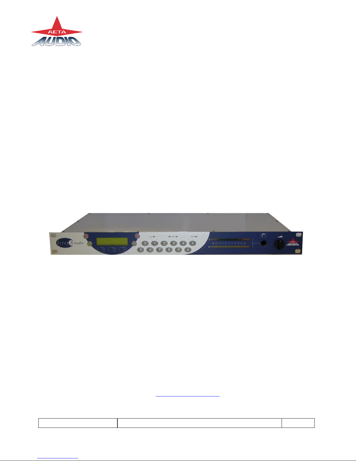
SCOOP STUDIO
User Manual
AETA AUDIO
361, avenue du Général de Gaulle – 92140 Clamart – FRANCE
Tel. +33 (0)1 41361212 – Fax +33 (0)1 41361213 – Telex 631178
Web : http://www.aeta.com


55 000 033 – Ed. A SCOOP STUDIO - User Manual L.A.F.
This document is the property of AETA and can not be duplicated without authorisation March 2002
Table of contents
1. SCOOP STUDIO – Easy quick Start ...............................1
2. Introduction ........................................................................2
2.1. Functions.............................................................................................. 2
2.2. Applications ......................................................................................... 3
3. Setting up the SCOOP STUDIO .......................................4
3.1. Power ................................................................................................... 4
3.2. Connection to the ISDN....................................................................... 4
3.3. Connection to the POTS ...................................................................... 4
4. SCOOP STUDIO STRUCTURE ......................................6
4.1. Front view ............................................................................................ 6
4.2. Scoop Studio status.............................................................................. 6
4.3. General synoptic diagram .................................................................... 7
5. Audio section.......................................................................8
5.1. Encoding and decoding........................................................................ 8
5.2. Audio Interfaces................................................................................. 11
5.3. Audio performance ............................................................................ 12
5.4. Audio monitoring............................................................................... 13
6. SCOOP STUDIO OPERATION: How it works. ..........14
6.1. Introduction........................................................................................ 14
6.2. User interface..................................................................................... 14
6.3. Scoop Studio Menu............................................................................ 15
7. How to Set-Up Profiles on the Scoop Studio..................20
7.1. What is a profile ?.............................................................................. 20
7.2. How to manage profiles on the Scoop Studio .................................... 20
8. Connecting 2 SCOOP STUDIO. .....................................23
8.1. Initiating a call ................................................................................... 23
8.2. Disconnecting a call........................................................................... 25
8.3. Auto Answering................................................................................. 25
8.4. Entering local Numbers ..................................................................... 25
8.5. Entering SPID Numbers ( USA )....................................................... 26

SCOOP STUDIO – User Manuel 55 000 033 – Ed. A
This document is the property of AETA and can not be duplicated without authorisation March 2002
9. POTS Information............................................................27
9.1. Factory default configuration .............................................................27
9.2. POTS modes.......................................................................................28
9.3. Network parameters ...........................................................................28
9.4. Error protection ..................................................................................29
10. Troubleshooting................................................................31
11. Tests ...................................................................................32
11.1. Audio section testing........................................................................32
11.2. Network test ...................................................................................32
12. ISDN modem information ...............................................34
12.1. ISDN Protocols ................................................................................34
12.2. ISDN CLEARING CAUSES ...........................................................34
13. How to open a SCOOP STUDIO ready for servicing ...37
14. Connectors layout.............................................................38
14.1. Remote Connector............................................................................38
14.2. POTS Interface.................................................................................38
14.3. ISDN Interface Network ..................................................................39
14.4. External DC connector .....................................................................39
14.5. Environment.....................................................................................39

55 000 033 – Ed. A SCOOP STUDIO - User Manual 1
This document is the property of AETA and can not be duplicated without authorisation March 2002
1. SCOOP STUDIO – Easy quick Start
1. Plug ISDN or POTS line to the appropriate socket on rear of unit
2. Plug in audio connections.
3. Power on the Scoop Studio via switch On/Off on rear panel of unit.
4. Select the appropriate network via the network menu
5.
- To use direct dial “Number” mode, enter a number
- To dial one of 5 last numbers press “green phone” key once.
- To use a profile number, enter a letter
For 2 last modes, select the profile number via keypad (left and right key)
6. Press “green phone” key again for dialling.
7. If busy or bad connection Press "ESC" then press the “green phone” key twice to
redial the last number dialled.
8. Connection status will be displayed in LCD screen once connected.

2 SCOOP STUDIO - User Manual 55 000 033 – Ed. A
This document is the property of AETA and can not be duplicated without authorisation March 2002
2. Introduction
2.1. Functions
The Scoop Studio is designed to enable radio broadcasters to conduct high quality live
two-way remote broadcasts, or two way commentaries with return cue, via ISDN or
POTS lines.1
2.1.1. Algorithms
The Scoop Studio contains a mono audio compressor/de-compressor (Codec) that
performs all necessary ISDN and POTS algorithms.
In ISDN mode, the user can select one of four operational audio standards:
1. Phone mode (G.711, 3,5kHz)
2. Live speech ( G.722, 7kHz, low delay )
3. Music CD quality (Layer II, 20kHz)2
4. Live concert (4SB-ADPCM,15kHz, proprietary low delay ) 2
In POTS mode, the user has only live speech mode ( CELP , 7kHz )
2.1.2. Audio interfaces
The Scoop Studio contains one audio input, one audio output and one headphone for
monitoring
2.1.3. Transmission
Using an ISDN line, transmission bit-rate is either 64kbps or 128kbps2. Using a POTS
line, transmission bit rate depends on the telecommunication network quality with a
maximum bit-rate of 33.6 kbps. The Scoop Studio transmits data at a minimum rate of
12.000 bits and at a maximum of 24.000 bits of information a second
The Scoop Studio can work in many countries using various ISDN standards.
As ISDN protocol may vary from country to country, consult
your AETA dealer before carrying your Scoop Studio abroad.
1Depending on configuration version
2On the 15kHz ISDN version

55 000 033 – Ed. A SCOOP STUDIO - User Manual 3
This document is the property of AETA and can not be duplicated without authorisation March 2002
2.2. Applications
News remotes.
Live sport commentaries with local contributors.
Remote two-way interviews.
Remote contributions into studio discussions.
Live music concerts.

4 SCOOP STUDIO - User Manual 55 000 033 – Ed. A
This document is the property of AETA and can not be duplicated without authorisation March 2002
3. Setting up the SCOOP STUDIO
3.1. Power
3.1.1. Optional DC supply
The Scoop Studio will also work on any external 8 to 15-volts DC source. A typical
source will be a car cigarette adapter. Connect your DC power cord to the socket at the
back panel of the unit ( labeled DC In 8-15 V 2A), and plug the other end into your DC
power source.
Note : See the chapter 14 for the connection.
3.2. Connection to the ISDN
Connect the (RJ45) connector of the ISDN cable into the socket on the back panel
marked "ISDN", and connect the other end of the cable into the ISDN wall socket.
The ISDN modem of the scoop is a S/T or a U interface depending on the unit type.
You can select the correct ISDN protocol for a given country from the menu.
Given the various kinds of ISDN protocols used in different countries or inside PBXs,
ISDN compatibility problems may occur. Please be sure to select the right protocol for
the country you are in. In case oftrouble please contact your AETA dealer for advice.
3.3. Connection to the POTS
Connect the (RJ11) connector of the telephone cable into the socket on the back panel
marked "ANALOG", and then connect the other end of the cable into the telephone wall
socket.
The Scoop Studio's RJ11 connector will accept 4 or 6 conductor modular plug, but only
the 2 center conductors, ( typically Red & Green ) are used.

55 000 033 – Ed. A SCOOP STUDIO - User Manual 5
This document is the property of AETA and can not be duplicated without authorisation March 2002
Caution: Every country has its own style of telephone connector. Consult your
engineers, your local AETA dealer for further advice.
Dialing methods
Telephones dial numbers either by pulsing the line, (you will hear a "clicking" sound
similar to that heard when dialing from a rotary dial telephone) or by sending audio
tones ( DTMF ) The Scoop Studio can dial using either pulse or DTMF tones.
Caution:
Do not connect the Scoop Studio to a telephone jack that provides power for
lighting a telephone's dial.
Do not connect the Scoop Studio to a party line or coin-operated telephone line.
Not suitable as an extension to a pay phone or use with a shared service line or
1+1 carrier system line.
You should disable call waiting if in use.
PBX and PABX applications
The internal modem of the Scoop Studio is only approved for use as an extension
instrument to compatible PBXs.
Contact AETA AUDIO S.A. or your local dealer for an up-to-date list of PBXs with
which the internal modem is compatible.
AETA AUDIO S.A can not guarantee that the Scoop Studio will operate correctly under
all possible conditions of connections to compatible PBXs. Any cases of difficulty
should be referred in the first instance to AETA AUDIO S.A.
6 SCOOP STUDIO - User Manual 55 000 033 – Ed. A
This document is the property of AETA and can not be duplicated without authorisation March 2002
4. SCOOP STUDIO STRUCTURE
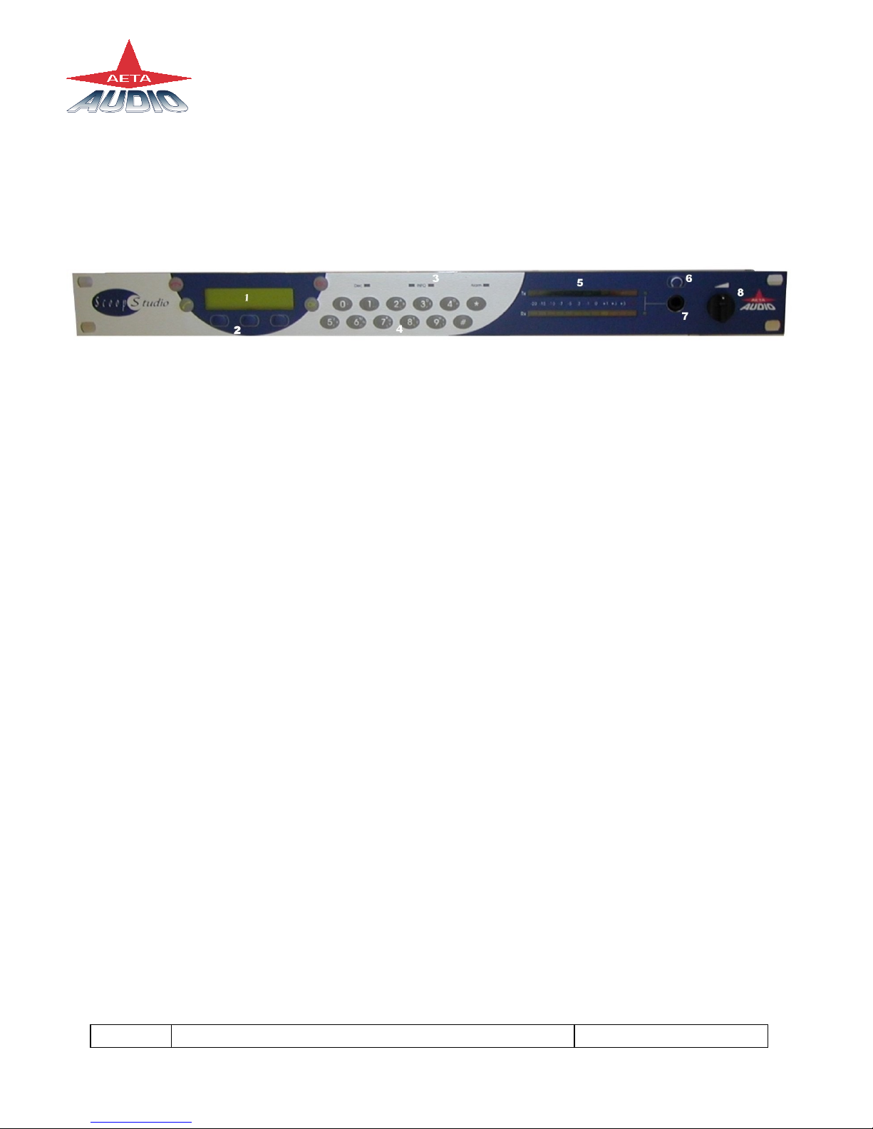
4.1. Front view
Figure 1 - Front panel
1 - LCD display 5 – Bargraph
2 - Function keys 6 – Monitoring selection
3 - Status LED’s 7 – Headphone socket
4 – Keypad 8 - Headphone volume adjustment
4.2. Scoop Studio status
There are 28 LED’s on the front panel providing the following information :
- Info ( 2 yellow LED’s ) : Information ( Future use ).
- Alarm (red) : When “on”, indicates a network problem.
- Dec (green) : When "on" indicates that a successful connection exists and the
Scoop Studio is decoding the POTS or ISDN signal.
- Tx Level meter : 11 LED’s ( scale –20 to + 5 VU ) + an Overload led
- Rx Level meter : 11 LED’s ( scale –20 to + 5 VU ) + an Overload led
55 000 033 – Ed. A SCOOP STUDIO - User Manual 7
This document is the property of AETA and can not be duplicated without authorisation March 2002
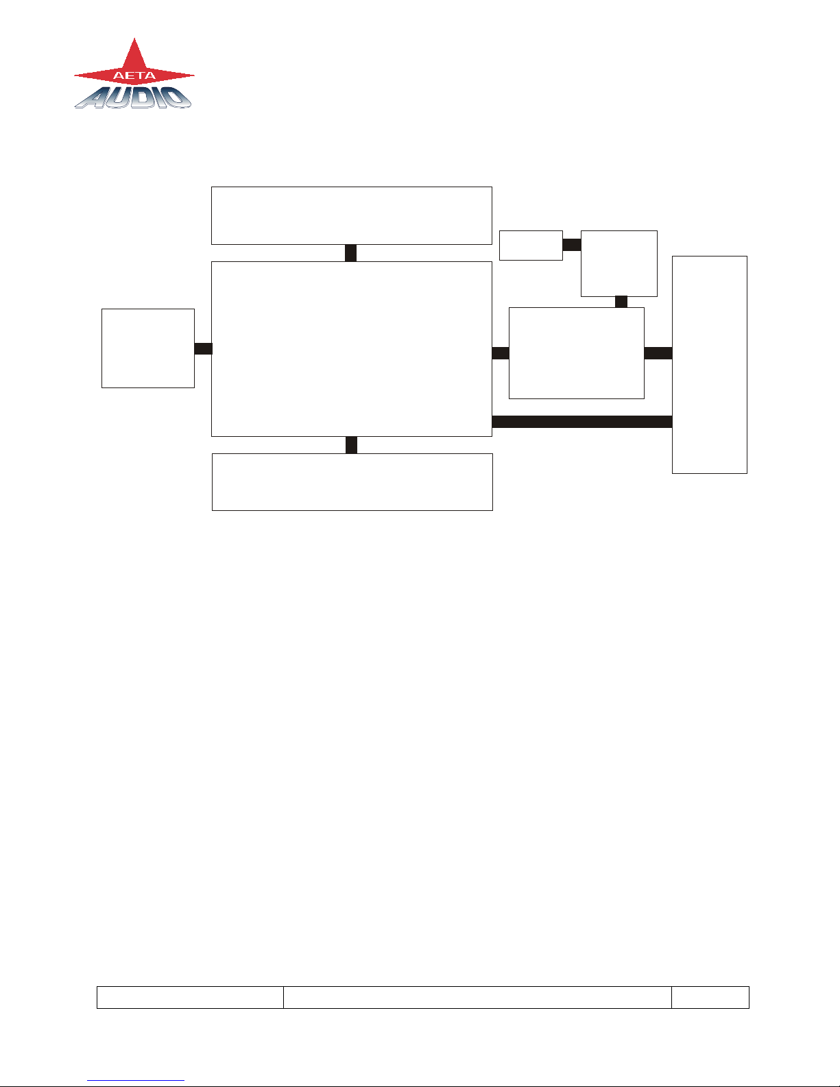
4.3. General synoptic diagram
Interfaces
board
Power board
Microprocessor
board
DSP board
Motherboard
LCD
Monitoring Board
Optional DC
Board
Figure 2 – Scoop Studio synoptic

8 SCOOP STUDIO - User Manual 55 000 033 – Ed. A
This document is the property of AETA and can not be duplicated without authorisation March 2002
5. Audio section
5.1. Encoding and decoding
Scoop Studio use includes a wide range of coding algorithms. First, one can select
among algorithms compliant with ISO and ITU-T1recommendations :
• G711;
• ITU-T G722 (mono at 64 kbit/s);
• MPEG Audio Layer II at 48, 32, 24 or 16 kHz, with programmable channel
mode and bit rate ;
MPEG Audio and G722 algorithms comply with ITU-T J52 recommendation for ISDN
transmission. Besides, other algorithms are available, that are so-called “proprietary”
because they do not comply with enforced standards :
• Proprietary MPEG Layer II at 64 kbit/s or 128 kbit/s (for compatibility with
ISDN codecs that are not compliant with the J52 recommendation) ;
• 4SB ADPCM, running in mono at a 128 kbit/s bit rate; the bandwidth with this
algorithm is 15 kHz ;
• TDAC mono, running at 64 kbit/s, with a 15 kHz bandwidth ; available as an
option.
The following describes some important features of the various available algorithms and
protocols.
5.1.1. Notes about G711
G711 is the standard coding used for voice transmission on public telephone networks.
This algorithm is used for links (via ISDN) with telephones or hybrid devices.
1former CCITT

55 000 033 – Ed. A SCOOP STUDIO - User Manual 9
This document is the property of AETA and can not be duplicated without authorisation March 2002
5.1.2. Notes about G722
With G722 coding, two synchronisation modes are available:
• “Statistical recovery” byte synchronisation method (alias SRT) ;
• H242 synchronisation; in this case, 1.6 kbit/s from the compressed data are
used for this.
H242 synchronisation is highly recommended when possible, as it features higher
reliability and faster recovery time, while degradation (because of the bit rate used for
framing) is minimal. This is recommended practice according to J52.
5.1.3. Notes about J52 and MPEG coding
The ITU-T J52 recommendation was defined in order to allow the interoperability of
various equipment over the ISDN1, using common coding standards. It includes the
following features:
• Interoperation procedures as per ITU-T H242 recommendation ;
• In the case of MPEG encoding, optional protection against transmission errors
(Reed-Solomon error correction codes).
It must be noted that, thanks to the interoperation protocol, J52 codecs, when setting up
a link, can negotiate automatically and agree on a configuration that is compatible with
the capability of both units (regarding bit rate, channel mode, etc.). In this way, when
the units differ in their capability (or make), the resulting configuration may be different
from expected beforehand, but in most cases the link will work and audio will be
transmitted.
As another useful consequence, this also gives users more tolerance to mistakes when
configuring the units on the two sides of the transmission links, as the codecs will adapt
automatically even with differences in the initial settings of the two units.
1J52 is not needed nor applicable to leased line connections

10 SCOOP STUDIO - User Manual 55 000 033 – Ed. A
This document is the property of AETA and can not be duplicated without authorisation March 2002
5.1.4. Notes about TDAC
As an option, the codec can also include the TDAC algorithm. TDAC is for Time
Domain Aliasing Cancellation ; this is a transform coding based on an MDCT
(Modified Discrete Cosine Transform), encoding a 15 kHz bandwidth mono signal at a
64 kbit/s bit rate. When the option is installed, three modes are available :
• TDAC mono full-duplex, running at 64 kbit/s, with a 15 kHz bandwidth ;
• G722/TDAC : G722 encoding, TDAC decoding, running both in mono at
64 kbit/s ;
• TDAC/G722 : TDAC encoding, G722 decoding (with SRT), running both in
mono at 64 kbit/s ; this mode is symmetric to the previous one.
5.1.5. Symmetric or asymmetric codec modes
The codec allows two communication modes:
Symmetric communication: in this mode, the encoder and decoder both use the same
coding algorithm with the same configuration (channel mode, etc.). In this case, the
communication is strictly symmetric full-duplex, with exactly the same coding
configuration used in both directions (local to remote and remote to local). This is
usually required when using proprietary algorithms.
Asymmetric communication: this mode is used for applications requiring different
coding configurations in the two directions. The J52 protocol allows such mode. To
give some examples, it is possible to transmit MPEG in one direction and G722 in the
other one.
With the TDAC option, asymmetric modes are also available wherein one direction is
G722 coded while the other one is TDAC coded. Such mode is useful e.g. in order to
get a low delay return path encoded in G722 while the send path is encoded with higher
quality but a higher delay.
55 000 033 – Ed. A SCOOP STUDIO - User Manual 11
This document is the property of AETA and can not be duplicated without authorisation March 2002
5.2. Audio Interfaces
5.2.1. Analogue audio Input
Audio characteristic are measured over a 20 to 20kHz bandwidth except when diffently
stated.
Format balanced
Connector 3-pin female XLR socket
Maximum input level +0 to +22 dBu by step pf 1dB ( menu )
Input impedance 10 kΩ
Common mode rejection ratio >60dB @ 1kHz
Table 1 – Input interface
5.2.2. analogue audio Outputs
The audio signal output is available on the line level output.
The monitoring source can be changed with the headphone key.
- If the led in the extension of the Tx bargraph is light, you have the local audio
signal on the headphone.
- If the led in the extension of the Rx bargraph is light, you have the return
audio signal on the headphone.
- If the same both leds are light, you have the local audio signal on the left ear
and the return on the right ear.
Line Out Interface :
Format Balanced
Connector 3-pin male XLR socket
Maximum output level
+0dBu to +22dBu by steps of 1dB (
software selection )
Output impedance ≤50 Ω
Output symmetry > 60 dB

12 SCOOP STUDIO - User Manual 55 000 033 – Ed. A
This document is the property of AETA and can not be duplicated without authorisation March 2002
Headphone Interface :
Connector 6.35mm jack socket
Maximum output level +20dBu
Load impedance ≥16 Ω
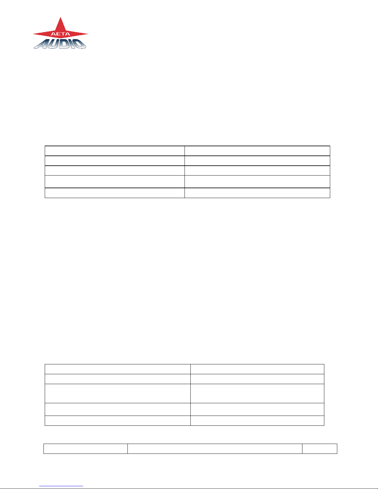
5.3. Audio performance
A ) Analog performance
Measurement condition:
- AD/DA Loop
- Sample frequency : 48kHz
Maximum Gain ( Input to Output ) +22dB
Signal to Noise ratio 84dBrms
Bandwidth 20Hz – 20 000 Hz ±0.5dB
Distortion ( THD+N) < 80 dB (0.01%) @ 950Hz
Table 2 – Audio performance
B) In ISDN mode
Data rate Sample frequency Bandwidth Algorithm
128 kbit/s 16/24/32/48kHz 20Hz - 20kHz MPEG II J52
128 kbit/s 16/24/32/48kHz 20Hz - 15kHz MPEG II
128 kbit/s 32kHz 20Hz - 15 kHz 4S/B
64 kbit/s 24kHz 20Hz - 10.5kHz MPEG II J52
64 kbit/s 24kHz 20Hz - 10.5kHz MPEG II
64 kbit/s 48kHz 20Hz - 8.2kHz MPEG II
64 kbit/s 16kHz 20Hz - 7kHz G722 SRT/H242
64 kbit/s 16kHz 300Hz - 3.5kHz G711- phone
64 kbit/s 32kHZ 20Hz – 15kHz TDAC
Table 3 – ISDN mode

55 000 033 – Ed. A SCOOP STUDIO - User Manual 13
This document is the property of AETA and can not be duplicated without authorisation March 2002
Note : In MPEG II without J52, Scoop Studio is compatible with other manufacturer
codecs.
C) POTS mode - CELP Algorithm
Data rate Audio quality Bandwidth : 40 Hz to 7 kHz (@ 24 kbps data rate)
12Kbit/s
14.4Kbit/s
16.8Kbit/s
19.2 Kbit/s
21.6 Kbit/s
24.0 Kbit/s
3.6kHz
4.3kHz
5.1 kHz
5.7 kHz
6.3 kHz
7.2 kHz
24 kbit/s can typically be achieved in all countries
that support V.34 modems on their public
switched networks.
Higher rate depends on line quality.
The CELP algorithm is optimised running at 24
kbit/s.
Table 4 – CELP
Note : CELP is a proprietary algorithm of France Telecom CNET
5.4. Audio monitoring
The 12 LED's labeled “Tx” on the front side of the Scoop Studio indicate the peak level
of the sending audio signal. The level display reference (0 dB) is 8 dB below the
clipping level.
The 12 LED's labeled “Rx” on the front side of the Scoop Studio indicate the peak level
of the receiving audio signal. The level display reference (0 dB) is 8 dB below the
clipping level.

14 SCOOP STUDIO - User Manual 55 000 033 – Ed. A
This document is the property of AETA and can not be duplicated without authorisation March 2002
6. SCOOP STUDIO OPERATION: How it works.
6.1. Introduction
Incoming audio into the Scoop Studio is digitized by a state-of-the-art A/D converter
and processed through the Scoop Studio's codec. The data is then sent via the internal
ISDN or POTS synchronous modem to the telephone network ( ISDN or POTS ) to a
remote Scoop Studio or another compatible ISDN Audio Codec. Operating with a very
fast DSP, the codec runs an algorithm modeling the digital audio signal, in order to
reduce the digitized audio data rate.
At the other end of the telephone network, the answering Scoop Studio reconstructs the
original audio signal with very little loss or induced artefacts and at an extremely low
audio delay time.
6.2. User interface
The user interface consists of a lexan matrix keypad and a LCD display. The keypad has
two sections.
- The first section is a 4x3 matrix including the numbers from 0 to 9,“*”, “#”.
Some keys have many functions :
2, 3, 4, 5, 6, 7, 8, 9, 0: for accessing to letters display on the key, press the key
several times.
Note : Space character is available on the “1” key.
- The second section is the Extended Keypad functions under the display.
There are 3 function keys not labeled. The key function depends of the menu, the
function label appears over the key on the second line of the display
- The third section is the special Keypad functions.
“OK” key to validate a choice.
“Esc” key to escape from a menu.
“Green phone” key to make a call.
“Red phone” key to on hook a call.
55 000 033 – Ed. A SCOOP STUDIO - User Manual 15
This document is the property of AETA and can not be duplicated without authorisation March 2002
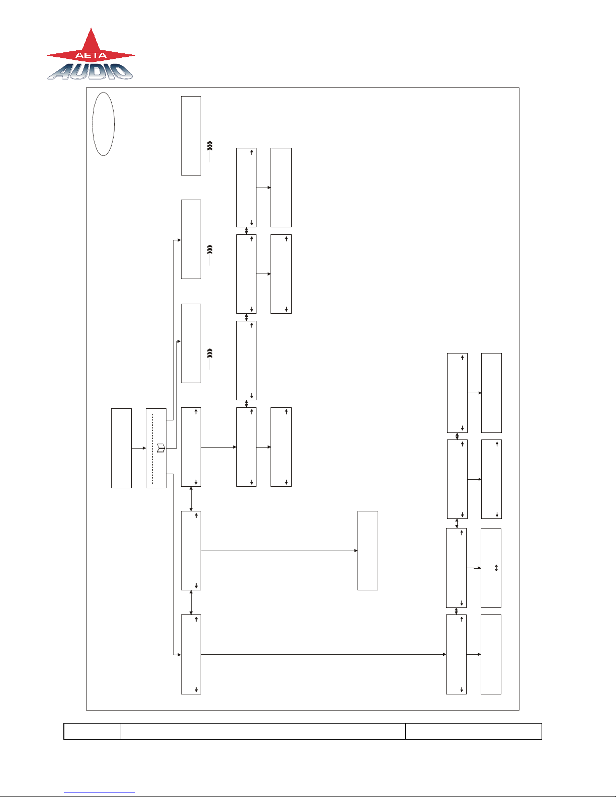
6.3. Scoop Studio Menu
1) Main menu
TOOLS SETUP
To scroll in the sub-menus use the keys under the word
If a second sub-menu exists, you can enter by pressing again the key under the word
At any time you can return to the main menu by pressing the Esc key.
Note : the symbol between “TOOLS” and “SETUP” means :
“DIRECTORY”
If you press “green phone” key, you access to the 5 last called number.
If you enter a letter, you access to the remote directory.
If you enter a number, you can make a direct call.
Note : If you have a restricted menu, you can disable it by pressing
the directory key and this following sequence: “1”,”6”,”4”,”3”
6.3.1. Scoop Studio default configuration
The Scoop Studio's “General reset” set default configuration is useful to configure the
modem in case communication difficulties are encountered.
Note : The stored calling numbers are not erased when you make a General reset.
16 SCOOP STUDIO - User Manual 55 000 033 – Ed. A
This document is the property of AETA and can not be duplicated without authorisation March 2002
ISDNANALOG
NETWORK
TOOLS TOOLS DIRECTORY SETUP ISDN SETUP ANALOG
TOOLS
Misc Status Local Audio Audio
Maintenance CodNet NetRemote
TOOLS SETUP
MAINTENANCE
LOOP2-network
MAINTENANCE MAINTENANCE
ABOUT
MAINTENANCE
USER ACCESS
Tests
OK
Download About
Micro : V1.00
U.access
Full Reduced
None
Loop2-network
Loop3-codec
AD/DA
Analog loop
Test tone
Coding test
Micro : V1.00
Cod : V4.00
Dec : V4.00
Xilinx : V1.01
O : SSGW2-1.22
CURRENT CONFIG
PMPEG L2 24K 1B
MISC
GENERAL RESET
MISC
LCD CONTRAST
MISC
English
MISC
KEYBOARD LOCK
General reset
CONFIRM : OK
LCD contrast
Off On
Language
OK
Keyboard lock
English
French
Or
Menu 3Menu 2 Menu 4
Menu 1
Cod
Other manuals for SCOOP STUDIO
2
Table of contents
Other Aeta Audio Systems Recording Equipment manuals


