Fostex 280 User manual

Owner’s
Manual
FOStGX

CAUTION
RISK
OF
ELECTRIC
SHOCK
DO
NOT
OPEN
CAUTION:
TO
REDUCE
THE
RISK
OF
ELECTRIC
SHOCK,
DO
NOT
REMOVE
COVER
(OR
BACK).
NO
USER-SERVICEABLE
PARTS
INSIDE.
REFER
SERVICING
TO
QUALIFIED
SERVICE
PERSONNEL.
A
The
lightning
flash
with
arrowhead
symbol.
/f\
within
an
equilateral
triangle,
is
intended
to
alert
the
user
to
the
presence
of
uninsulated
/
M
\
"dangerous
voltage"
within
the
product's
en-
/
V
\
closure
that
may
be
of
sufficient
magnitude
to
constitute
a
risk
of
electric
shock
to
persons
"WARNING"
"
TO
REDUCE
THE
RISK
OF
FIRE
OR
ELECTRIC
SHOCK
DO
NOT
EXPOSE
THIS
APPLIANCE
TO
RAIN
OR
MOIS¬
TURE.
1
1
SAFETY
INSTRUCTIONS
1.
Read
Instructions
—
All
the
safety
and
operating
instruc¬
tions
should
be
read
before
the
appliance
is
operated.
2.
Retain
Instructions
-
The
safety
and
operating
instructions
should
be
retained
for
future
reference.
3.
Heed
Warnings
—
All
warnings
on
the
appliance
and
i
n
the
operating
instructions
should
be
adhered
to.
4.
Follow
Instructions
-
All
operating
and
use
instructions
should
be
followed.
5.
Water
and
Moisture
—
The
appliance
should
not
be
used
near
water
-
for
example,
near
a
bathtub,
washbowl,
kit¬
chen
sink,
laundry
tub,
in
a
wet
basernent,
or
near
a
swim¬
ming
pool,
and
the
like.
6.
Carts
and
Stands
—
The
appliance
should
be
used
only
with
a
cart
or
stand
that
is
recommended
by
the
manu¬
facturer.
An
appliance
and
cart
combination
should
be
moved
with
care.
Quick
stops,
excessive
force,
and
uneven
surfaces
may
cause
the
appliance
and
cart
combination
to
overturn.
7.
Wall
or
Ceiling
Mounting
—The
appliance
should
be
mount¬
ed
to
a
wall
or
ceiling
only
as
recommended
by
the
manu¬
facturer.
8.
Ventilation
—
The
appliance
should
be
situated
so
that
its
location
or
position
does
not
interfere
with
its
proper
venti¬
lation.
For
example,
the
appliance
should
not
be
situated
on
a
bed,
sofa,
rug,
or
similar
surface
that
may
block
the
ventilation
openings;
or,
placed
in
a
buill-in
installation,
such
as
a
bookcase
or
cabinet
that
may
impede
the
flow
of
air
through
the
ventilation
openings.
The
exclamation
point
within
an
equilateral
triangle
is
intended
to
alert
the
user
to
the
presence
of
important
operating
and
mainte¬
nance
(servicing)
instructions
in
the
literature
accompanying
the
appliance.
9.
H
e
at
-
The
appliance
should
be
situated
away
from
heal
sources
such
as
radiators,
heat
registers,
stoves,
or
other
appliances
(including
amplifiers)
that
produce
heat.
10.
Power
Sources
—
The
appliance
should
be
con
nected
to
a
power
supply
only
of
the
type
described
in
the
operating
instructions
or
as
marked
on
the
appliance.
11.
Grounding
or
Polarization
-
The
precautions
that
should
be
taken
so
that
the
grounding
or
polarization
means
of
an
appliance
is
not
defeated.
12.
Power
Cord
Protection
-
Pdwer
supply
cords
should
be
routed
so
that
they
are
not
likely
to
be
walked
on
or
pinched
by
items
placed
upon
or
against
them,
paying
particular
attention
to
cords
at
plugs,
convenience
recep¬
tacles,
and
the
point
where
they
exit
from
the
appliance.
13.
Cleaning
-
The
appliance
should
be
cleaned
only
as
recommended
by
the
manufacturer.
14.
Nonuse
Periods
-
The
power
cord
of
the
appliance
should
be
unplugged
from
the
outlet
when
left
unused
for
a
long
period
of
time.
15
Object
and
Liquid
Entry
—
Care
should
be
taken
so
that
objects
do
not
fall
and
liquids
are
not
spilled
into
the
enc¬
losure
through
openings.
16
Damage
Requiring
Service
—
The
appliance
should
be
serviced
by
qualified
service
personnel
when:
A.
The
power
supply
cord
or
the
plug
has
been
damaged;
Or
B.
Objects
have
fallen,
or
liquid
has
been
spilled
into
the
appliance;
or
C.
The
appliance
has
been
exposed
to
rain;
or
D.
The
appliance
does
not
appear
to
operate
normally
or
exhibits
a
marked’
change
in
performance;
or
E.
The
appliance
has
been
dropped,
or
the
enclosure
damaged.
17
Servicing
—
The
user
should
not
attempt
to
service
the
appliance
beyond
that
described
in
the
operating
instruc¬
tions
All
other
servicing
should
be
referred
to
qualified
service
personnel.
1989
Sep
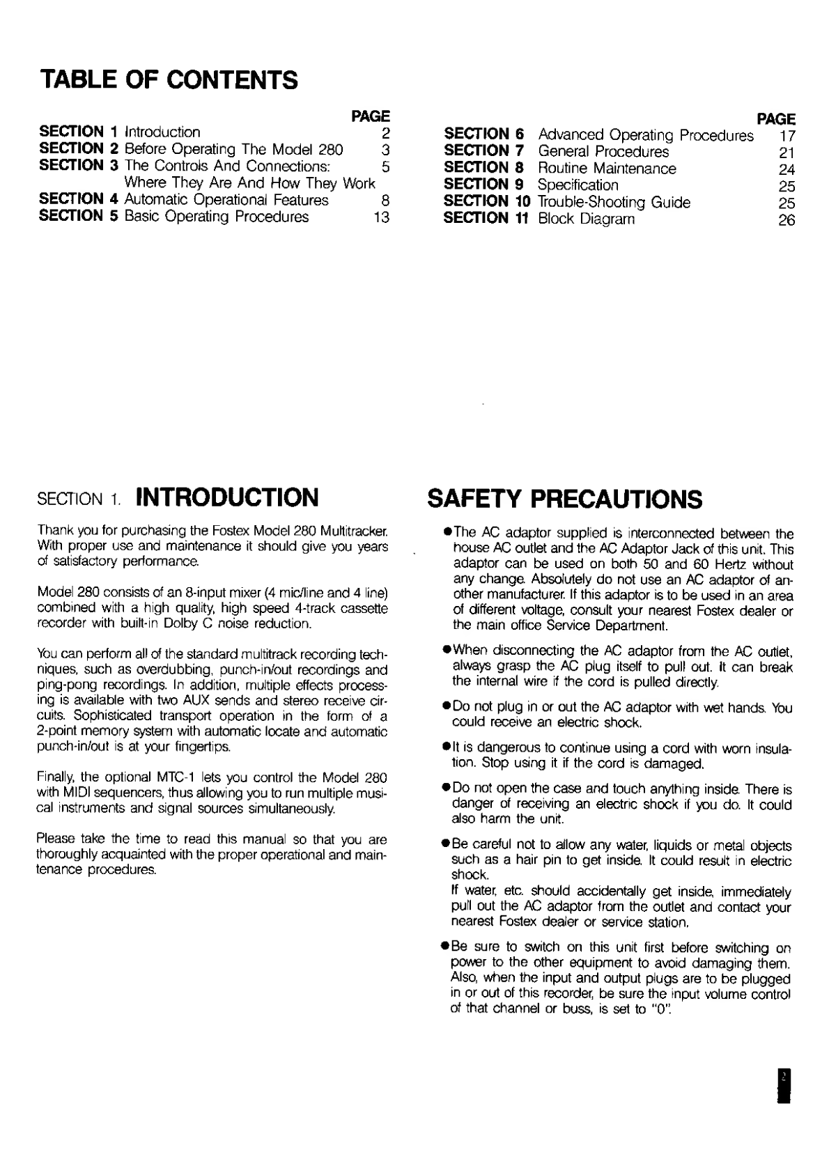
TABLE
OF
CONTENTS
mGE
SECTION
1
Introduction
2
SECTION
2
Before
Operating
The
Model
280
3
SECTION
3
The
Controls
And
Connections:
5
Where
They
Are
And
How
They
Work
SECTION
4
Automatic
Operational
Features
8
SECTION
5
Basic
Operating
Procedures
13
PAGE
SECTION
6
Advanced
Operating
Procedures
17
SECTION
7
General
Procedures
21
SECTION
8
Routine
Maintenance
24
SECTION
9
Specification
25
SECTION
10
Trouble-Shooting
Guide
25
SECTION
11
Block
Diagram
26
SECTION
1
.
INTRODUCTION
Thank
you
for
purchasing
the
Fostex
Model
280
Multitracker.
With
proper
use
and
maintenance
it
should
give
you
years
of
satisfactory
performance.
Model
280
consists
of
an
8-input
mixer
(4
mic/line
and
4
line)
combined
with
a
high
quality,
high
speed
4-track
cassette
recorder
with
built-in
Dolby
C
noise
reduction.
You
can
perform
all
of
the
standard
multitrack
recording
tech¬
niques,
such
as
overdubbing,
punch-in/out
recordings
and
ping-pong
recordings.
In
addition,
multiple
effects
process¬
ing
is
available
with
two
AUX
sends
and
stereo
receive
cir¬
cuits.
Sophisticated
transport
operation
in
the
form
of
a
2-point
memory
system
with
automatic
locate
and
automatic
punch-in/out
is
at
your
fingertips.
Finally,
the
optional
MTC-1
lets
you
control
the
Model
280
with
MIDI
sequencers,
thus
allowing
you
to
run
multiple
musi¬
cal
instruments
and
signal
sources
simultaneously.
Please
take
the
time
to
read
this
manual
so
that
you
are
thoroughly
acquainted
with
the
proper
operational
and
main¬
tenance
procedures.
SAFETY
PRECAUTIONS
•The
AC
adaptor
supplied
is
interconnected
between
the
house
AC
outlet
and
the
AC
Adaptor
Jack
of
this
unit.
This
adaptor
can
be
used
on
both
50
and
60
Hertz
without
any
change
Absolutely
do
not
use
an
AC
adaptor
of
an¬
other
manufacturer.
If
this
adaptor
is
to
be
used
in
an
area
of
different
voltage,
consult
your
nearest
Fostex
dealer
or
the
main
office
Service
Department.
•When
disconnecting
the
AC
adaptor
from
the
AC
outlet,
always
grasp
the
AC
plug
itself
to
pull
out.
It
can
break
the
internal
wire
if
the
cord
is
pulled
directly.
•Do
not
plug
in
or
out
the
AC
adaptor
with
wet
hands
You
could
receive
an
electric
shock.
•It
is
dangerous
to
continue
using
a
cord
with
worn
insula¬
tion.
Stop
using
it
if
the
cord
is
damaged.
•Do
not
open
the
case
and
touch
anything
inside
There
is
danger
of
receiving
an
electric
shock
if
you
do.
It
could
also
harm
the
unit.
•Be
careful
not
to
allow
any
water,
liquids
or
metal
objects
such
as
a
hair
pin
to
get
inside
It
could
result
in
electric
shock.
If
water,
etc.
should
accidentally
get
inside
immediately
pull
out
the
AC
adaptor
from
the
outlet
and
contact
your
nearest
Fostex
dealer
or
service
station.
•Be
sure
to
switch
on
this
unit
first
before
switching
on
power
to
the
other
equipment
to
avoid
damaging
them.
Also,
when
the
input
and
output
plugs
are
to
be
plugged
in
or
out
of
this
recorder,
be
sure
the
input
volume
control
of
that
channel
or
buss,
is
set
to
"0".

SECTION
2.
BEFORE
OPERATING
THE
MODEL
280
There
are
a
few
important
considerations
which
you
should
be
aware
of
before
you
attempt
to
operate
the
Model
280:
1.
R
ecording
Format.
Standard
cassette
recorders
record
up
to
two
tracks
at
a
time;
two
in
one
direction
(Side
A)
and
two
in
the
opposite
direction
(Side
B).
As
shown
in
the
diagram
below,
the
multi¬
track
format
allows
recording
of
up
to
four
tracks
in
the
same
direction.
After
completing
a
multitrack
tape
on
your
280,
remove
both
cassette
tabs
to
prevent
accidental
erasure
or
re-recordings.
2.
Tape
Speed.
Standard
cassette
recorders
record
and
play
back
at
1-7/8
ips
(inches
per
second).
The
model
280
records
and
plays
back
at
3-3/4
ips—twice
the
speed
for
better
fidelity.
Thus
a
C-90
will
yield
22.5
minutes
of
recording
time;
a
C-60,
15
minutes,
and
a
C-30,
7.5
minutes.
3.
Type
of
Tape.
Use
High
Bias
(CrOi
Type
II)
tapes
ONLY.
We
recommend
Maxell
UD-XL2
or
TDK
SA
or
the
equivalent—always
look
for
the
70
psec
EQ
designation.
NEVER
USE:
(1)
C-120
type
tapes
of
any
kind
because
the
tape
is
too
thin
to
withstand
the
rigors
of
multitrack
recording;
(2)
metal
tape
4.
Impedance.
All
electronic
devices
have
a
characteristic
called
impedance
which
refers
to
resistance
in
the
circuit(s).
The
unit
of
meas¬
urement
is
stated
in
Ohms
(G).
In
general,
input
impedance
should
be
about
ten
times
higher
than
output
impedance.
When
connecting
other
equipment
to
the
280,
check
to
see
that
there
is
an
impedance
match
(specifically
with
micro¬
phones);
if
a
mis-match
occurs,
anything
from
sound
deterio¬
ration
to
serious
damage
could
result.
NOTE:
You’ll
find
that
most
“outboard"
gear
available
today
and
most
musical
instruments
can
be
connected
to
your
280
readily
and
without
worry.
The
main
exception
is
electric
guitars,
just
because
there
is
such
a
wide
variety
of
design,
plus
the
tendency
to
cus¬
tomize
stock
designs
for
a
"hotter
sound.”
Thus
in
some
cases,
a-"direct
box"
will
be
necessary.
Never
plug
anything
rated
in
watts
(W)
directly
to
a
280
input.
5.
The
difference
between
track
and
channel.
“Track"
refers
to
a
physical
space
on
the
cassette
tape
(1
~4);
“channel”
refers
to
a
signal
pathway
through
the
mixer
(1
—8),
as
shown
in
the
diagram
below.
The
difference
between
track
and
channel.
Tracks
1
~4
Channels
1
~8
I
Other manuals for 280
1
Table of contents
Other Fostex Recording Equipment manuals

Fostex
Fostex MR-8MKII User manual

Fostex
Fostex VF160EX User manual

Fostex
Fostex X-55 User manual

Fostex
Fostex R8 User manual

Fostex
Fostex MR-8 MKII User manual

Fostex
Fostex Foundation 2000RE User manual

Fostex
Fostex X-24 User manual

Fostex
Fostex FR-2 User manual

Fostex
Fostex VF-160 User manual

Fostex
Fostex DMT-8 User manual


