JVC VU-LD20U User manual

VU-LD20U
LINE DOUBLER
Thank you for purchasing this product.
Before using your new purchase, please read this instruction manual thoroughly. And, after
reading, be sure to store this instruction manual in a safe place for future reference.
POWER INPUT 6
S-Video Comp
Prog. 1 Prog. 2 Prog. 3
INPUT SELECTOR
Prog. 4 Prog. 5 AVC
Prog. 6 Prog. 7 Prog. 8 Prog. 9 Prog. 10
REMOTE
SENSOR
FAROUDJA
PICTURE PLUS
LINE DOUBLER VU-LD20U
Instruction Manual
LPT0410-001A
For Customer Use:
Enter below the Serial No. which is
located on the rear of the cabinet.
Retain this information for future
reference.
Model No. VU-LD20U
Serial No.
Downloaded from: https://www.usersmanualguide.com/

2
CAUTION: TO REDUCE THE RISK OF ELECTRIC SHOCK,
DO NOT REMOVE COVER (OR BACK).
NO USER-SERVICEABLE PARTS INSIDE.
REFER SERVICING TO QUALIFIED SERVICE PERSONNEL.
The lightning flash with arrowhead symbol, within an equilateral triangle, is intended to alert the user to
the presence of uninsulated “dangerous voltage” within the product’s enclosure that may be of sufficient
magnitude to constitute a risk of electric shock to persons.
The exclamation point within an equilateral triangle is intended to alert the user to the presence of impor-
tant operating and maintenance (servicing) instructions in the literature accompanying the product.
IMPORTANT:
RECORDING OF COPYRIGHTED TELEVISION PROGRAMS MAY VIOLATE COPYRIGHT LAW.
WARNING:
TO REDUCE THE RISK OF FIRE OR ELECTRIC SHOCK, DO NOT EXPOSE THIS PRODUCT TO RAIN OR MOISTURE.
CAUTION:
TO PREVENT ELECTRIC SHOCK HAZARD, DO NOT USE THIS (POLARIZED) PLUG WITH AN EXTENSION CORD, RECEP-
TACLE OR OTHER OUTLET UNLESS THE BLADES CAN BE FULLY INSERTED TO PREVENT BLADE EXPOSURE.
CAUTION
RISK OF ELECTRIC SHOCK
DO NOT OPEN
DANGER D’ELECTROCUTION
NE PAS OUVRIR
La flèche symbolisant le tonnerre à l’intérieur d’un triangle équilatéral a pour but de prévenir
l’utilisateur de la présence d’une “tension dangereuse” non isolée se trouvant à l’intérieur du
dispositif; elle est d’une magnitude suffisante pour constituer un risque de décharge électrique.
Le point d’exclamation à l’intérieur d’un triangle équilatéral a pour but de prévenir l’utilisateur de la
présence d’importantes instructions concernant l’entretien et le un fonctionnement indiquées dans
les textes accompagnant le dispositif.
MISE EN GARDE :
AFIN DE REDUIRE LES RISQUES D’INCENDIE OU DE DECHARGE ELECTRIQUE, NE PAS EXPOSER CET
APPAREIL A LA PLUIE OU A L’HUMIDITE.
ATTENTION :
AFIN DE REDUIRE LES RISQUES DE DECHARGE ELECTRIQUE, NE PAS UTILISER LA FICHE (POLARISEE) DE
CET APPAREIL AVEC UN PROLONGATEUR, UNE PRISE OU UNE AUTRE PRISE DE COURANT SAUF SI CES
LAMES PEUVENT ETRE INSEREES A FOND.
REMARQUE :
ETANT DONNE QUE CE PROJECTEUR EST UN APPAREIL QUI DOIT ETRE BRANCHE, LA PRISE MURALE DOIT
ETRE INSTALLEE PRES DU PROJECTEUR ET DOIT ETRE FACILEMENT ACCESSIBLE.
AVERTISSEMENT: POUR ELIMINER TOUT RISQUE D’ELECTROCUTION NE PAS
OUVRIR LE COUVERCLE (OU LA PARTIE ARRIERE).
AUCUNE PIECE PEPARABLE PAR L’UTILISATEUR NE SE TROUVE A L’INTERIEUR.
POUR TOUTE INTERVENTION D’ENTRETIEN OU DE REPARATION SE CONFIER
AUX TECHNICIENS QUALIFIES.
AVERTISSEMENT
Downloaded from: https://www.usersmanualguide.com/

3
FEATURES
Stunning image quality through highly accurate signal processing
Our original three-dimension Y/C separation circuit has been employed together with the image processing circuit made
by Faroudja in the decoder section, the line doubler section, and the bandwidth expander section. Consistent signal
processing with high accuracy from input to output provides stunning image quality.
- Line doubler section
Signals from the decoder section are progressively processed in the line doubler section. Faroudja's unique motion
algorithm rids jaggies and flickers from images by converting film images of 30 frames per second into 24 frames per
second and applying total still image processing. Reproduction through double the number of scanning lines realizes
natural progressive processing with higher accuracy and less missing information.
- NTSC color decoder section
Faroudja's most reliable decoder for 10-bit processing and Analog Device's high performance AD converter jointly
offer highly accurate AD conversion. In addition, Faroudja's original chroma band expansion circuit provides film-like
images of high definition, greatly enhancing color transition, trangent and resolution.
- Bandwidth expander section
In the bandwidth expander section, signals are refined to obtain higher image quality after the line doubling process-
ing. Bandwidth of Y (luminance) signal is doubled through the non-liner processing. Expanded bandwidth increases
image detail, improves trangent and enhances sharpness of images, achieving dramatic development in video image
quality and striking beauty and impression.
- Y/C separation circuit section
Our original three-dimension filter correctly separates signals having motion images as well as signals having station-
ary images, considerably reducing cross-color and dot interference.
Selector function to connect 18 video sources at the maximum
Selectable inputs of three types, VIDEO IN, S-VIDEO IN and COMPONENT IN, allow 18 video sources at the maximum
to be connected depending on combination.
Various image quality adjustments
Various image quality adjustments, from basic adjustments of sharpness, contrast, etc. to advanced adjustments such as
black level extension adjustment, are available and offer a possible use as an equalizer. These adjustments can be
memorized in every program. Images are easily reproduced according to the preprogrammed adjustments just by switching
the programs depending on image materials.
The Faroudja name is the registered trademark of Faroudja, Inc. in the United States.
CONTENTS
IMPORTANT SAFEGUARDS ....................................................................................... 4, 5
OVERVIEW OF THE PRODUCT .................................................................................. 6, 7
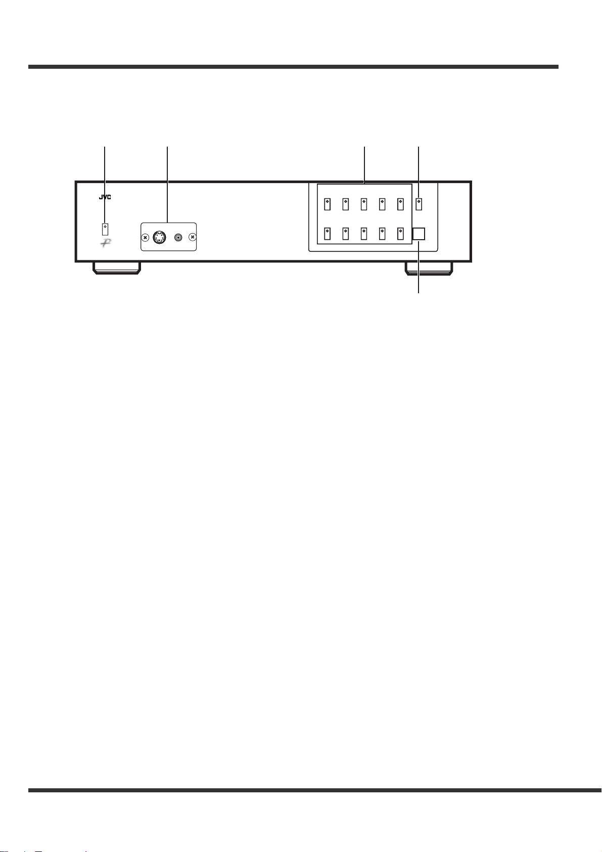
Front panel ............................................................................................................................. 6
Rear panel ............................................................................................................................. 7
OVERVIEW OF THE REMOTE CONTROL.................................................................. 8, 9
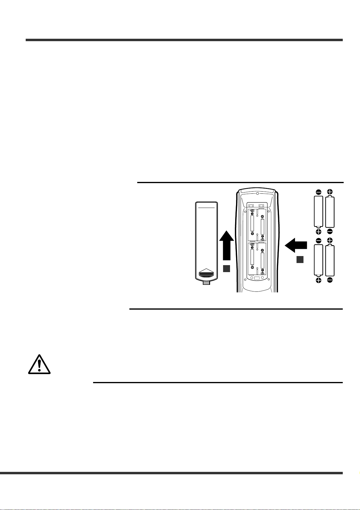
Battery installation ................................................................................................................. 9
PREPARATION .............................................................................................................. 10
Preparing for operation ........................................................................................................ 10
System configuration ........................................................................................................... 10
CONNECTIONS ........................................................................................................ 11-14
Connection with a D-ILA, LCD projector .............................................................................. 11
Connection with a Projector ................................................................................................. 12
Connection with a VCR ........................................................................................................ 13
Connection with a DVD player ............................................................................................. 13
Connection with an AV amplifier .......................................................................................... 14
INPUT SETTING ....................................................................................................... 15 -18
Setting program ............................................................................................................. 15, 16
Program setting items .......................................................................................................... 17
Program title setting ............................................................................................................. 18
BASIC USE ..................................................................................................................... 19
LINE DOUBLER .................................................................................................................. 19
KEY LOCK ........................................................................................................................... 19
IMAGE QUALITY ADJUSTMENT ............................................................................ 20 - 23
Basic image quality adjustment ........................................................................................... 20
Advanced image quality adjustment .................................................................................... 21
Adjustment items ........................................................................................................... 22, 23
Control this line doubler by using a personal computer ............................................ 24, 25
TROUBLESHOOTING .................................................................................................... 26
INDEX ............................................................................................................................. 27
SPECIFICATIONS .................................................................................................... 28, 29
Electric ................................................................................................................................. 28
General ................................................................................................................................ 29
Connectors .......................................................................................................................... 29
What’s included in the box ................................................................................................... 29
Downloaded from: https://www.usersmanualguide.com/

4
Please read all these instructions carefully regarding your Line double before you begin operating
it. Follow all warnings and instructions marked on the Line doubler. Thank you.
ANTENNA
LEAD IN WIRE
ANTENNA
DISCHARGE UNIT
(NEC SECTION 810-20)
GROUNDING
CONDUCTORS
(NEC SECTION 810-21)
GROUND CLAMPS
POWER SERVICE GROUNDING
ELECTRODE SYSTEM
(NEC ART 250, PART H)
GROUND CLAMP
ELECTRIC
SERVICE
EQUIPMENT
NEC – NATIONAL ELECTRICAL CODE
EXAMPLE OF ANTENNA GROUNDING
IMPORTANT SAFEGUARDS
1 Read Instructions
All the safety and operating instructions should be read
before the product is operated.
2 Retain Instructions
The safety and operating instructions should be retained
for future reference.
3 Heed Warnings
All warnings on the product and in the operating in-
structions should be adhered to.
4 Follow Instructions
All operating and use instructions should be followed.
5 Cleaning
Unplug this product from the wall outlet before clean-
ing. Do not use liquid cleaners or aerosol cleaners.
Use a damp cloth for cleaning.
6 Attachments
Do not use attachments not recommended by the prod-
uct manufacturer as they may cause hazards.
7 Water and Moisture
Do not use this product near water — for example, near
a bath tub, wash bowl, kitchen sink, laundry tub, in a
wet basement, or near a swimming pool, and the like.
8 Accessories
Do not place this product on an unstable cart, stand,
tripod, bracket, or table. The product may fall, causing
serious injury to a child or adult, and serious damage
to the product. Use only with a cart, stand, tripod,
bracket, or table recommended by the manufacturer,
or sold with the product. Any mounting of the product
should follow the manufacturer’s instructions, and
should use a mounting accessory recommended by the
manufacturer.
9A product and cart combination should be moved with
care. Quick stops, excessive force, and uneven sur-
faces may cause the product and cart combination to
overturn.
10 Ventilation
Slots and openings in the cabinet are provided for ven-
tilation and to ensure reliable operation of the product
and to protect it from overheating, and these openings
must not be blocked or covered. The openings should
never be blocked by placing the product on a bed, sofa,
rug, or other similar surface. This product should not
be placed in a built-in installation such as a bookcase
or rack unless proper ventilation is provided or the
manufacturer’s instructions have been adhered to.
11 Power Sources
This product should be operated only from the type of
power source indicated on the marking label. If you
are not sure of the type of power supply to your home,
consult your product dealer or local power company.
For products intended to operate from battery power,
or other sources, refer to the operating instructions.
12 Grounding or Polarization
This product is equipped with a polarized alternating-
current line plug (a plug having one blade wider than
the other). This plug will fit into the power outlet only
one way. This is a safety feature. If you are unable to
insert the plug fully into the outlet, try reversing the plug.
If the plug should still fail to fit, contact your electrician
to replace your obsolete outlet. Do not defeat the safety
purpose of the polarized plug.
13 Power-Cord Protection
Power-supply cords should be routed so that they are
not likely to be walked on or pinched by items placed
upon or against them, paying particular attention to
cords at plugs, convenience receptacles, and the point
where they exit from the product.
14 Outdoor Antenna Grounding
If an outside antenna or cable system is connected to
the product, be sure the antenna or cable system is
grounded so as to provide some protection against volt-
age surges and built-up static charges.
Article 810 of the National Electrical Code, ANSI/
NFPA 70, provides information with regard to proper
grounding of the mast and supporting structure, ground-
ing of the lead-in wire to an antenna discharge unit,
size of grounding conductors, location of antenna-dis-
charge unit, connection to grounding electrodes, and
requirements for the grounding electrode.
Downloaded from: https://www.usersmanualguide.com/

5
15 Lightning
For added protection for this product during a lightning
storm, or when it is left unattended and unused for long
periods of time, unplug it from the wall outlet and dis-
connect the antenna or cable system. This will prevent
damage to the product due to lightning and power-line
surges.
16 Power Lines
An outside antenna system should not be located in
the vicinity of overhead power lines or other electric
light or power circuits, or where it can fall into such
power lines or circuits. When installing an outside an-
tenna system, extreme care should be taken to keep
from touching such power lines or circuits as contact
with them might be fatal.
17 Overloading
Do not overload wall outlets, extension cords, or inte-
gral convenience receptacles as this can result in fire
risk or electric shock.
18 Object and Liquid Entry
Never push objects of any kind into this product through
openings as they may touch dangerous voltage points
or short-out parts that could result in a fire or electric
shock. Never spill liquid of any kind on the product.
19 Servicing
Do not attempt to service this product yourself as open-
ing or removing covers may expose you to dangerous
voltage or other hazards. Refer all servicing to quali-
fied service personnel.
20 Damage Requiring Service
Unplug this product from the wall outlet and refer ser-
vicing to qualified service personnel under the follow-
ing conditions:
(a) When the power-supply cord or plug is damaged.
(b)
If liquid has been spilled, or objects have fallen into the
product.
(c) If the product has been exposed to rain or water.
(d) If the product does not operate normally by follow-
ing the operating instructions. Adjust only those
controls that are covered by the operating instruc-
tions as an improper adjustment of other controls
may result in damage and will often require exten-
sive work by a qualified technician to restore the
product to its normal operation.
(e) If the product has been dropped or damaged in
any way.
(f) When the product exhibits a distinct change in per-
formance – this indicates a need for service.
21 Replacement Parts
When replacement parts are required, be sure the ser-
vice technician has used replacement parts specified
by the manufacturer or have the same characteristics
as the original part. Unauthorized substitutions may
result in fire, electric shock or other hazards.
22 Safety Check
Upon completion of any service or repairs to this prod-
uct, ask the service technician to perform safety checks
to determine that the product is in proper operating
condition.
23 Heat
The product should be situated away from heat sources
such as radiators, heat registers, stoves, or other prod-
ucts (including amplifiers) that produce heat.
Declaration of Conformity
Model Number : VU-LD20U
Trade Name : JVC
Responsible Party : JVC Americas Corp.
Address : 1700 Valley Road Wayne.
N.J. 07470
Telephone Number : 973-315-5000
This device complies with Part 15 of FCC Rules.
Operation is subject to the following two conditions:
(1) This device may not cause harmful interference, and (2) this device must accept any interference received,
including interference that may cause undesired operation.
Changes or modifications not expressly approved by the party responsible for compliance could void the user’s
authority to operate the equipment.
COMPLIANCE NOTICE OF INDUSTRY CANADA
This Class B digital apparatus complies with Canadian ICES-003.
NOTICE DE CONFORMITE AU CANADA
Cet appareil numérique de la classe B est comforme à la norme NMB-003 du Canada.
Downloaded from: https://www.usersmanualguide.com/

6
OVERVIEW OF THE PRODUCT
POWER INPUT 6
S-Video Comp
wer
t
Prog. 1 Prog. 2 Prog. 3
INPUT SELECTOR
Prog. 4 Prog. 5 AVC
Prog. 6 Prog. 7 Prog. 8 Prog. 9 Prog. 10
REMOTE
SENSOR
FAROUDJA
PICTURE PLUS
LINE DOUBLER VU-LD20U
q
Front panel
1POWER button
Press the POWER button to turn on the product while
the MAIN SW on the rear panel is ON. Press this but-
ton again to turn it off. The power indicator illuminates
in red during stand-by when the MAIN SW is ON. The
power indicator illuminates in green while the power is
supplied.
2S-VIDEO 6 / VIDEO 6 INPUT terminals
Use to connect with a device having a VIDEO or S-
VIDEO terminal such as a video camera or videodisc
player. Remove the cover by loosening the two
cover-fixing screws using a screwdriver to use these
terminals.
3Program buttons (Prog. 1 to 10)
Use to select the programs of the memorized input
terminals, etc. The indicator of the selected program
illuminates. The recommended settings have been
preprogrammed at the time of delivery from the fac-
tory. The video mute operates about 2 seconds when
the programs are switched.
4AVC button
Use to display functions of an AV amplifier having on-
screen function which is connected to the AVC termi-
nal on the rear panel.
One press on this button illuminates the indicator in
orange and displays the images supplied to the AVC
input. Another press on this button displays the im-
ages of the previously selected program. You can't
adjust the quality of the images supplied to the AVC
terminal.
5REMOTE SENSOR
The REMOTE SENSOR receives the commands
from the remote control.
Downloaded from: https://www.usersmanualguide.com/

7
Rear panel
q
io
we
3
S-VIDEO INVIDEO IN
OUTPUT 2
REC-OUT AVC
R G B H V
COMPONENT IN
YUV
2
1
YUV
4
5
S-VIDEO INVIDEO IN COMPONENT IN
6
RS-232C
OUTPUT 1 MAIN SW
ONOFF
u
y
t
r
1OUTPUT 1 terminals (BNC)
Use to connect with a video device having RGB termi-
nals such as a Projector. HD and VD are output at 1.0
Vp-p (75Ωtermination).
2S-VIDEO (S-Y/C-1 to 5) IN / VIDEO IN (VIDEO-1 to
5) terminals
Use to connect with a device having Video or S-Video
terminals as a VCR or videodisc player.
3MAIN SW
Set the MAIN SW to ON to turn on the main power
and to OFF to turn it off. Set this switch to OFF before
long absence of operation of the product.
4OUTPUT 2 terminal (mini D-SUB 15P)
Use to connect with an LCD projector. HD and VD
are output at the TTL level.
5RS-232C terminal (mini D-SUB 9P)
Use to connect with an PC.
6REC-OUT terminal
Use to output supplied signals directly. When com-
posite video signals or S-video signals are supplied,
the composite video signals or the S-video signals are
output. (Signals from a device connected to the
COMPONENT IN terminals are not output.)
7AVC terminal
Use to connect with an AV amplifier having on-screen
function to display its functions. You can't adjust the
quality of images supplied to the AVC terminal.
8COMPONENT IN (Y/U/V-1 to 6) terminals
Use to connect with a device which provides video
component signals such as a DVD player.
9Power supplying terminal
Use to connect with the attached power cable.
Downloaded from: https://www.usersmanualguide.com/

8
OVERVIEW OF THE REMOTE CONTROL
1Illumination button
One press on this button illuminates the titles of the
buttons about 10 seconds. ({, }, $and %and
ENTER buttons are not illuminated. However, they
light with stored light after the remote control is put in
a bright place for a while.) Another press on this
button cancels illumination.
2PROGRAM button
Use to select the programs in turn.
3PICTURE button
Use to adjust the image quality together with $and
%buttons. See page 20 for details.
SHARPNESS button
Use to adjust sharpness (image quality).
CONT(CONTRAST) button
Use to adjust contrast.
BRIGHT button
Use to adjust brightness.
COLOR button
Use to adjust color intensity.
TINT button
Use to adjust tint.
16
4{{
{{
{, }}
}}
}, $$
$$
$and %%
%%
%buttons
Press these buttons to select items or change set-
tings while a menu screen or image quality adjust-
ment screen is displayed.
5PROGRAM buttons, 1 to 10
Use to select the program numbers directly.
6POWER button
Press the ON side to turn on the product while the
MAIN SW on the rear panel is set to ON. Press the
OFF side to turn it off.
7ESC button
Use to display the previous menu screen. One press
on this button without a menu screen displayed, the
title of the currently selected program, input terminals
and video format are displayed about 5 seconds.
8ENTER button
Use to fix a selected item on a menu screen.
SHARP
CONT
BRIGHT COLOR
ESC
TINT
PROGRAM POWER
ON
OFF
VC MENU
LIST
123
456
789
10
ENTER
AVC
q
wy
u
o
!0
i
e
t
!1
r
Downloaded from: https://www.usersmanualguide.com/

9
Handling the remote control
Do not drop it or give it a shock.
Do not spill liquid on it or put it on a wet object.
Do not wipe it with volatile liquid such as benzine or thinner.
Wrong usage of batteries may cause a leak of inside solution or an explosion. Please follow the instructions below.
• Load the batteries in the correct positions.
• Do not use new and old batteries together, or batteries of different type together.
• Take the batteries out before long absence of operation of the remote control. In case of a leak of inside solution, wipe up the
solution off the remote control and load new batteries.
• Do not take the batteries apart or throw them into flames.
• Do not use alkaline dry batteries. Wrong usage may lead to generating heat, an explosion and a leak of inside solution causing
an injury or burn.
• Do not try to recharge the batteries.
Handling batteries
NOTE
Batteries installation
1Push the back cover in the direction of
the arrow to remove it.
2Load the batteries making sure that they
are positioned correctly (+ to +, and - to -).
3Attach the back cover.
• Use four AA size dry batteries.
1
™
9VC MENU button
Use to display the VIDEO EQUALIZING MENU for
image quality adjustment. Press this button again to
cancel the VIDEO EQUALIZING MENU. See page 21
for details.
0LIST button
Use to confirm and set the contents of the programs.
See page 15 for details.
{AVC button
Use to display functions of an AV amplifier connected
to the AVC terminal.
Downloaded from: https://www.usersmanualguide.com/

10
PREPARATION
System configuration
This product can be connected with 2 projectors and 18 video sources at the maximum.
Projector etc.
VU-LD20U
DVD player
Laser disc player
CS tuner VCR
POWER INPUT 6
S-Video Comp
Prog. 1 Prog. 2 Prog. 3
INPUT SELECTOR
Prog. 4 Prog. 5 AV C
Prog. 6 Prog. 7 Prog. 8 Prog. 9 Prog. 10 REMOTE
SENSOR
FAROUDJA
PICTURE PLUS
STANDBY
OPERATE
LAMP
TEMP
EMERGENCY
VIDEO
COMPUTER
SETTING
QUICK
ALIGN
-
2
+
3
LINE DOUBLER VU-LD20U
Preparing for operation
Load dry batteries in the remote control. (See page 9.)
Connect with a projector. (See page 11 and 12.)
Connect with a video source. (See page 13 and 14.)
Insert the power plug into a socket.
Set the programs. (See page 15 to 18.)
• Connection with a VCR
• Connection with a DVD player
• Connection with an AV amplifier
• Connection with a D-ILA, LCD projector
• Connection with a Projector
• Selection of input terminals
• Setting of IN/OUT signals
Downloaded from: https://www.usersmanualguide.com/

11
Important!
• Turn off the power before connection.
• Insert the plug completely.
• Unplug by holding the plug, not by pulling the cable out.
• Also refer to the users' guide of the D-ILA, LCD projector.
CONNECTIONS
Connection with a D-ILA, LCD projector
3
S-VIDEO INVIDEO IN
OUTPUT 2
REC-OUT AVC
R G B H V
COMPONENT IN
YUV
2
1
YUV
4
5
S-VIDEO INVIDEO IN COMPONENT IN
6
RS-232C
OUTPUT 1 MAIN SW
ONOFF
Y
PC
AUDIO
AUDIO
AUDIO
AUDIO OUT
REMOTE
Y/C VIDEO
Y
P
B
/B-Y
P
R
/R-Y
L
R
H/C
S
V
R
G
B
COMPUTER
OUT
RS-232C
RGB cable
Example of the advanced image qual-
ity adjustment screen
VIDEO™EQUALIZING™MENU™2
™™COLOR-COMP™™™™:1
™™GAMMA-COR™™™™™:OFF
™™DC-TRN-COR™™™™:OFF
™™PRE/OVER™™™™™™:1
™™Y-EDGE™™™™™™™™:OFF
™™C-EDGE™™™™™™™™:OFF
™™™™MENU™3
VIDEO™EQUALIZING™MENU™3
™™PICTURE-EX™™™™:OFF
™™COLOR-EX™™™™™™:OFFŁ
Ł
™™™™MENU™1
• HD and VD from the OUTPUT2 (mini D-SUB 15P) are output at the TTL level.
Downloaded from: https://www.usersmanualguide.com/

12
Important!
• Turn off the power before connection.
• Insert the plug completely.
• Unplug by holding the plug, not by pulling the cable out.
• Also refer to the users' guide of the projector.
CONNECTIONS (continued)
Connection with a Projector
3
S-VIDEO INVIDEO IN
OUTPUT 2
REC-OUT AVC
R G B H V
COMPONENT IN
YUV
2
1
YUV
4
5
S-VIDEO INVIDEO IN COMPONENT IN
6
RS-232C
OUTPUT 1 MAIN SW
ONOFF
HD signal
B signal
G signal
R signal
VD signal
HD signal
B signal
G signal
R signal
VD signal
5BNC cable
Example of the advanced image qual-
ity adjustment screen
VIDEO™EQUALIZING™MENU™2
™™COLOR-COMP™™™™:1
™™GAMMA-COR™™™™™:OFF
™™DC-TRN-COR™™™™:OFF
™™PRE/OVER™™™™™™:4
™™Y-EDGE™™™™™™™™:OFF
™™C-EDGE™™™™™™™™:OFF
™™™™MENU™3
VIDEO™EQUALIZING™MENU™3
™™PICTURE-EX™™™™:OFF
™™COLOR-EX™™™™™™:OFFŁ
Ł
™™™™MENU™1
Downloaded from: https://www.usersmanualguide.com/

13
Connection with a VCR
Important!
• Turn off the power before connection.
• Use the correct connecting cables which fit to the terminals.
• Insert the plug completely.
• Unplug by holding the plug, not by pulling the cable out.
• Also refer to the users' guide of the connected device because some devices have terminals of different names or need different
connection.
3
S-VIDEO INVIDEO IN
OUTPUT 2
REC-OUT AVC
R G B H V
COMPONENT IN
YUV
2
1
YUV
4
5
S-VIDEO INVIDEO IN COMPONENT IN
6
RS-232C
OUTPUT 1 MAIN SW
ONOFF
S-video cable
VCR
Video cable
To S-Video output terminalTo Video output terminal
DVD player
Video cable
To Component video out terminals
(Y/C
B
/C
R
or Y/P
B
/P
R
)
Y signal
C
B
or P
B
signal
C
R
or P
R
signal
3
S-VIDEO INVIDEO IN
OUTPUT 2
REC-OUT AVC
R G B H V
COMPONENT IN
YUV
2
1
YUV
4
5
S-VIDEO INVIDEO IN COMPONENT IN
6
RS-232C
OUTPUT 1 MAIN SW
ONOFF
Connection with a DVD player
Example of the program setting
screen
See page 15 to 18 for setting and the
setting items.
PROGRAM™1:
™INPUT™TERMINAL™:S-Y/C-3
™VIDEO™FORMAT™™™:
™COLOR™MATRIX™™™:
™LINE™DOUBLER™™™:ON
™VIDEO™BAND™™™™™:WIDE
™PROG-TITLE™™:VTR
Example of the program setting
screen
See page 15 to 18 for setting and the
setting items.
PROGRAM™1:
™INPUT™TERMINAL™:Y/U/V-1
™VIDEO™FORMAT™™™:15.7k
™COLOR™MATRIX™™™:YCbCr
™LINE™DOUBLER™™™:ON
™VIDEO™BAND™™™™™:WIDE
™PROG-TITLE™™:DVD
• Noises may appear on images when a videotape with unstable sync signals is played back. In such a case, it is recommend to
use a VCR with a built-in TBC (Time Base Corrector) circuit.
• Noises may appear on images when a videotape with poor recording quality is played back, it is forwarded being played back, or
the product receives television signals in poor signal area. This is due to unstable sync signals, not a product's failure.
Downloaded from: https://www.usersmanualguide.com/

14
Important!
• Turn off the power before connection.
• Use the correct connecting cables which fit to the terminals.
• Insert the plug completely.
• Unplug by holding the plug, not by pulling the cable out.
• Also refer to the users' guide of the connected device because some devices have terminals of different names or need different
connection.
Connection with an AV amplifier
AV amplifier
Video cable
to MONITOR OUT
3
S-VIDEO INVIDEO IN
OUTPUT 2
REC-OUT AVC
R G B H V
COMPONENT IN
YUV
2
1
YUV
4
5
S-VIDEO INVIDEO IN COMPONENT IN
6
RS-232C
OUTPUT 1 MAIN SW
ONOFF
CONNECTIONS (continued)
Downloaded from: https://www.usersmanualguide.com/

15
INPUT SETTING
1Turn on the connected devices.
2Turn on the MAIN SW on the rear panel.
The main power indicator illuminates in red.
3Press the POWER button.
The power indicator illuminates in green.
4Press the LIST button on the remote
control.
• The SOURCE PROGRAM LIST is displayed.
• The SOURCE PROGRAM LIST-1 is displayed when any of
the program numbers 1 to 5 is selected.
• The SOURCE PROGRAM LIST-2 is displayed when any of
the program numbers 6 to 10 is selected.
• Press the LIST button again to cancel the SOURCE PRO-
GRAM LIST.
• The SOURCE PROGRAM LIST is automatically canceled
when there is no press on the buttons for 15 seconds.
SOURCE™PROGRAM™LIST-1
PROGRAM™1:LD
PROGRAM™2:DVD
PROGRAM™3:HD
PROGRAM™4:VTR1
PROGRAM™5:VTR2
™™™ENTER:PROGRAMING™MENU
SOURCE™PROGRAM™LIST-2
PROGRAM™6:
PROGRAM™7:
PROGRAM™8:
PROGRAM™9:
PROGRAM10:
™™™ENTER:PROGRAMING™MENU
SHARP
CONT
BRIGHT COLOR
ESC
TINT
PROGRAM POWER
ON
OFF
VC MENU
LIST
123
456
789
10
ENTER
AVC
£ ¢
£
¡™
¡¡
∞
Program (1 to 10)
button
Program (1 to 10)
button
PROGRAM button
™
POWER INPUT 6
S-Video Comp
Prog. 1 Prog. 2 Prog. 3
INPUT SELECTOR
Prog. 4 Prog. 5 AVC
Prog. 6 Prog. 7 Prog. 8 Prog. 9 Prog. 10
REMOTE
SENSOR
FAROUDJA
PICTURE PLUS
3
S-VIDEO INVIDEO IN
OUTPUT 2
REC-OUT AVC
R G B H V
COMPONENT IN
YUV
2
1
YUV
4
5
S-VIDEO INVIDEO IN COMPONENT IN
6
RS-232C
OUTPUT 1 MAIN SW
ONOFF
LINE DOUBLER VU-LD20U
Setting program
You can set programs for every input signal and select them by the program buttons. Ten program buttons on the front panel specify
not the input terminals but the programs. So, it is necessary to connect your video sources to optional terminals and set programs in
advance.
Downloaded from: https://www.usersmanualguide.com/

16
INPUT SETTING (continued)
5Press the {{
{{
{or }}
}}
}button on the remote
control to select a program number to be
set.
The selected program is displayed in yellow.
6Press the ENTER button.
The program setting screen of the selected program number is
displayed.
7Press the $$
$$
$or %%
%%
%button on the remote
control to select the INPUT TERMINAL.
• Select the INPUT TERMINAL corresponding to the connected
input terminal. Refer to the table on the right.
8Press the ENTER button.
• Images supplied to the selected input terminal are displayed.
9Press the {{
{{
{or }}
}}
}button on the remote
control to select an item to be changed.
• The selected item is displayed in yellow.
• Some items can not be changed due to the INPUT TERMI-
NAL setting, etc. You can not select such items.
• See page 17 for detailed description of each item.
10
Press the $$
$$
$or %%
%%
%button on the remote
control to change the setting of the
selected item.
11
Press the ENTER button.
• The changed setting is fixed.
• The input terminal is also changed at the same time when
you change the INPUT TERMINAL setting.
12
Press the VC MENU button.
The program setting screen is canceled.
Type of input terminal Display
Video terminal VIDEO-1to 6
S-Video terminal S-Y/C-1 to 6
Component(Y/U/V)terminal
Y/U/V-1 to 6
PROGRAM™1:Ł
™INPUT™TERMINAL™:S-Y/C-1
™VIDEO™FORMAT™™™:
™COLOR™MATRIX™™™:
™LINE™DOUBLER™™™:ON
™VIDEO™BAND™™™™™:WIDE
™PROG-TITLE™™:LD
PROGRAM™1:Ł
™INPUT™TERMINAL™:S-Y/C-1
™VIDEO™FORMAT™™™:
™COLOR™MATRIX™™™:
™LINE™DOUBLER™™™:ON
™VIDEO™BAND™™™™™:WIDE
™PROG-TITLE™™:LD
PROGRAM™1:Ł
™INPUT™TERMINAL™:S-Y/C-1
™VIDEO™FORMAT™™™:
™COLOR™MATRIX™™™:
™LINE™DOUBLER™™™:OFF
™VIDEO™BAND™™™™™:WIDE
™PROG-TITLE™™:LD
• The program setting screen is automatically canceled when there is no press on the buttons for 15 seconds. Even when the
program setting screen disappears before pressing the ENTER button, the changed settings are effective.
Downloaded from: https://www.usersmanualguide.com/

17
Program setting items
1 INPUT TERMINAL setting
Use this item to select the INPUT TERMINAL.
The settings of VIDEO FORMAT, COLOR MATRIX and LINE DOUBLER may be fixed and not be changed due to the INPUT TERMI-
NAL setting. Refer to the following table for setting. (Yes : Changeable, No: Not changeable)
2 VIDEO FORMAT setting
Use this item to set the VIDEO FORMAT only when Y/U/V is selected.
15.7k .....For general setting.
31.5k ..... Select when progressive signals from a DVD player for high-definition, etc. are supplied to the input termi-
nal.
HDTV ....Select when HDTV signals from an LD player, an NTSC/HD converter, etc. are supplied to the input termi-
nal.
• FORMAT ERROR sign is displayed about 30 seconds when the VIDEO FORMAT not corresponding to the input signals is
selected.
3 COLOR MATRIX setting
Use this item to set the COLOR MATRIX only when Y/U/V is selected.
YCbCr ... Select when a DVD player having the component video output terminals (Y, Cb, Cr) is connected to the input
terminal.
YPbPr ....Select when an LD player, an NTSC/HD converter having the HDTV component video output terminals (Y,
Pb, Pr) is connected to the input terminal.
4 LINE DOUBLER setting
Use this item to carry out conversion of interlace signals into progressive signals.
ON .........Conversion is carried out. (For general setting.)
OFF .......Conversion is not carried out.
5 VIDEO BAND setting
Use this item to set the VIDEO BAND.
NORMAL .... For general video band. Select for an input video source with poor S/N.
WIDE .......... For wide video band. More detailed images are displayed. Noises increase when the input video source
has poor S/N. (For general setting.)
6 PROG-TITLE setting
Use to set the PROG-TITLE. See the next page for setting.
PROGRAM™1:
™INPUT™TERMINAL™:S-Y/C-1
™VIDEO™FORMAT™™™:
™COLOR™MATRIX™™™:
™LINE™DOUBLER™™™:ON
™VIDEO™BAND™™™™™:WIDE
™PROG-TITLE™™:LD
INPUT TERMINAL setting VIDEO S-Y/C Y/U/V
VIDEO FORMAT No (Not selectable) No (Not selectable) Yes
COLOR MATRIX No (Not selectable) No (Not selectable) Yes
VIDEO FORMAT setting
LINE DOUBLER Yes Yes 15.7k
31.5k or HDTV
Yes No (Fixed to OFF)
Type of input terminal Display
Video terminal VIDEO-1to 6
S-Video terminal S-Y/C-1 to 6
Component(Y/U/V)terminal
Y/U/V-1 to 6
Downloaded from: https://www.usersmanualguide.com/

18
1Carry out steps 1 to 6 on page 16.
The program setting screen of the selected program number is
displayed.
2Press the {{
{{
{ or }}
}}
}button on the remote
control to select PROG-TITLE.
3Press the ENTER button.
The TITLE EDIT screen is displayed and you can select the first
letter of the title.
• You can enter ten letters at the maximum.
4Press the $$
$$
$, %%
%%
%, {{
{{
{ or }}
}}
}button on the
remote control to select a letter and press
the ENTER button.
• The selected letter is fixed and the setting screen for the next
letter is displayed.
• Select or ➔and press the ENTER button to change the
next letter on the left or right.
• Select SPACE and press the ENTER button to enter a space.
5Repeat the above operation to enter the
title.
6Press the $$
$$
$, %%
%%
%, {{
{{
{ or }}
}}
}button on the
remote control to select END and press
the ENTER button (or the VC MENU
button).
The menu screen disappears.
• Press the ESC button to display the program setting screen
again.
• The menu screen disappears when the tenth letter is entered.
PROGRAM™1:
™INPUT™TERMINAL™:S-Y/C-1
™VIDEO™FORMAT™™™:
™COLOR™MATRIX™™™:
™LINE™DOUBLER™™™:ON
™VIDEO™BAND™™™™™:WIDE
™PROG-TITLE™™:LD
PROGRAM™1:
™INPUT™TERMINAL™:S-Y/C-1
™VIDEO™FORMAT™™™:
™COLOR™MATRIX™™™:
™LINE™DOUBLER™™™:ON
™VIDEO™BAND™™™™™:WIDE
™PROG-TITLE™™:LD
PROGRAM™1:™™™™TITLE™EDITŁ
™™™
™™™™™™™LD
________
™ABCDEFGHIJKLMNOPQRSTUV
™WXYZ0123456789.+-*/=()
™abcdefghijklmnopqrstuv
™wxyz"',:;™SPACE™
•¶
™END
__
PROGRAM™1:™™™TITLE™EDITŁ
™™™
™™™™™™™VD
________
™ABCDEFGHIJKLMNOPQRSTUV
™WXYZ0123456789.+-*/=()
™abcdefghijklmnopqrstuv
™wxyz"',:;™SPACE™
•¶
™END
__
Program title setting
INPUT SETTING (continued)
➔
Downloaded from: https://www.usersmanualguide.com/

19
BASIC USE ( To see the images from the connected devices)
1Turn on the power of the connected
devices.
2Turn on the MAIN SW on the rear panel.
The main power indicator illuminates in red.
3Press the POWER button.
The power indicator illuminates in green.
4Select a program.
Press the Program button (1 to 10), the PROGRAM ªor º
button on the remote control.
The images of the selected program are displayed. The settings
of the selected program are displayed about 5 seconds at this time.
• Press the ESC button to cancel the images.
• No images are displayed when you select a program in which
no signals are supplied to the preprogram input terminal. HD
and VD outputs are stopped after NO SIGNAL sign is dis-
played about 30 seconds. They are output again when you
carry out any kind of operation.
• Press the PROGRAM buttons on the remote control to select
the programs in turn. Each press on the ªbutton changes
the programs as 1➔2➔3➔... Each press on the ºbutton
changes the program as 1➔10➔9➔...
PROGRAM™1:™™™™™™™™™™™LD
VIDEO-1™™™™™™™™™™™15.7k
Program titleProgram No.
Input terminal name Video format
• New images are displayed in 2 seconds after changing the programs.
• Images may not appear on the screen at the moment of changing the video channel when a VCR is connected.
• Images which are reproduced by special playback (Still image, Speed search, Slow play, etc.) may have noises or not be
displayed when a VCR is connected. Noises may also appear on images when an old tape is played back.
• FORMAT ERROR is displayed about 30 seconds when a signal not corresponding to the setting of VIDEO FORMAT on the
program setting screen is supplied. In such a case, change the VIDEO FORMAT setting on the program setting screen or
change the input signals.
LINE DOUBLER
The LINE DOUBLER function converts the images by interlace scanning into those by progressive scanning to output. Set the LINE
DOUBLER to ON on the program setting screen to use this function.
• The 3-2 PULL DOWN function operates for film images. If the images are not processed by the 3-2 PULL DOWN function, the
edges of moving images may become scratchy.
• It may take about 2 seconds until the 3-2 PULL DOWN function operates when the images are switched by the chapter search etc.
• Images may appear blurred or shake vertically when the LINE DOUBLER is set to ON with a game player, etc. connected. In
such a case, set the LINE DOUBLER to OFF.
• The edges of moving images may become scratchy when using a picture element display device such as an LCD or monitor.
KEY LOCK
The KEY LOCK function is provided to prevent wrong button operation.
1. Press the Program 1 button on the product and the POWER button at the same time.
When pressing these keys for the KEY LOCK function during standby, the power is turned on and the KEY LOCK mode is
activated automatically.
2. To cancel the KEY LOCK mode,
Press the Program 10 button on the product and the POWER button at the same time.
Downloaded from: https://www.usersmanualguide.com/

20
IMAGE QUALITY ADJUSTMENT
1Select a program to adjust the image
quality
Press the PROGRAM (1 to 10) button, the PROGRAM ªor
ºbutton on the remote control.
2Press the PICTURE button on the remote
control (SHARPNESS, CONT, BRIGHT,
COLOR, or TINT) to adjust the desired item.
The adjustment screen of the selected item is displayed.
3Press the $$
$$
$or %%
%%
%button on the remote
control to change the setting.
• Press the $button to decrease the setting, and press the %
button to increase the setting. The setting can be changed
from -31 to 31 (Except SHARPNESS).
• Press the {or }button to select the adjustment item and
change the setting only for SHARPNESS. (See below.)
• The adjustment screen disappear in about 15 seconds with-
out pressing the $or %button.
• Press the ESC button to cancel the adjustment screen.
CONTRAST‡°°°°°·°°°°°‚™™0
CONTRAST‡°°°°°·°°·°°‚™15
Basic image quality adjustment
• The settings of the image quality adjustment are memorized in each program. The memorized settings will be kept even when
the power is turned off.
Adjustment items
1. SHARPNESS adjustment
Use this item to adjust the sharpness of images in every frequency. Press the SHARP button to display the image
quality setting screen.
1. Press the {or }button to display SHARPNESS FREQUENCY in yellow.
2. Press the $or %button to set SHARPNESS FREQUENCY.
• Each press on the %button change the setting as 1(LOW)➔2(STD)➔3(MID)➔4(HIGH). Each press on the $
button changes it in reverse.
3. Press the {or }button to display GAIN in yellow.
4. Press the $or %button to adjust GAIN.
• Each press on the %button sharpens the images. Each press on the $button softens the images.
2. CONTRAST adjustment
Use this item to adjust the ratio of black and white contrast of images. Press the CONT button to display the contrast
setting screen. Each press on the %button strengthens the contrast. Each press on the $button weakens the
contrast.
3. BRIGHT adjustment
Use this item to adjust the luminance of the whole image. Press the BRIGHT button to display the bright setting
screen. Each press on the %button brightens the images. Each press on the $button darkens the images.
4. COLOR adjustment
Use this item to adjust the color intensity of images. Press the COLOR button to display the color setting screen.
Each press on the %button increase the color intensity. Each press on the $button decrease the color intensity.
5. TINT adjustment
Use this item to adjust the color tone of images. Press the TINT button to display the tint setting screen.
Each press on the %button shifts green on skin color. Each press on the $button shifts purple on skin color.
• When the settings of the image quality adjustment (e.g. contrast and luminance) are increased too much, the images may not be
displayed clearly. It happens due to a large signal supplied to the product, not to a product's failure.
Downloaded from: https://www.usersmanualguide.com/
Table of contents
Other JVC Recording Equipment manuals

JVC
JVC KM-H3000 User manual

JVC
JVC HM -DR10000EU User manual

JVC
JVC BR-HD50U - Compact HDV/DV Format Video... Quick start guide

JVC
JVC XL-R910SL User manual

JVC
JVC HR-S8006UM User manual

JVC
JVC KSSRA100 - Vehicle Sirius Satellite Radio... Guide

JVC
JVC SEA-50 User manual

JVC
JVC XL-R910SL User manual

JVC
JVC SEA-60 User manual

JVC
JVC GW-SP100U User manual