AEV Energia User manual

PAG. 6 EnergiaEnergia
EnergiaEnergia
Energia
Electronic Equipment
Electronic Equipment
Electronic Equipment
AEV S.P.A VI A D E L L A TE C N I C A N.3 I-40050 AR G E L AT O BO L O G N A ITA LY WWW.A E V .N E T WWW.A E V -U S A .C O M E-M A I L : I N F O @A E V .N E T
Contents
Guarantee ....................................................................... 2
Feedback ........................................................................ 2
Technical Support .......................................................... 2
Factory Service and Repairs .......................................... 2
Shipping Instruction ...................................................... 2
SAFETYPRECAUTIONS .............................................. 3
SICHERHEITSINWEISE ................................................ 3
PRECAUTIONS ............................................................. 4
Introduction ................................................................... 7
Features ......................................................................... 7
Inputs and Channels Functions ..................................... 7
Outputs .......................................................................... 7
External Controls ............................................................ 8
Monitoring ..................................................................... 8
Display ........................................................................... 8
General Functions .......................................................... 8
Selection and Editing commands ................................... 9
Description of Menus .................................................... 9
Main Menu .................................................................... 9
Input Configuration ..................................................... 10
Mike Setup ................................................................... 11
Internal Voice Processor Setup .................................... 13
Line Setup .................................................................... 14
AES/EBU Setup ........................................................... 16
Channel Assign ............................................................ 17
System Setup ............................................................... 18
GPI/GPO Setup ............................................................. 19
Password Setup ........................................................... 19
Clock Timer setup ........................................................ 20
SAVE / RECALLSetup ................................................. 20
Cue Setup ..................................................................... 21
OUT/AUX Configuration ............................................. 22
Direct commands ......................................................... 23
Direct commands : Input channels section .................. 23
Direct commands: Control Room Section..................... 24
Direct commands : Control Studio Section .................. 24
Direct commands: Headset section .............................. 25
Direct commands: CUE Speaker Section ...................... 25
Direct commands: Timer section .................................. 25
4 Telco Option .............................................................. 26
How to ......................................................................... 29
How to use TELCO buses ............................................ 29
Private communication ................................................. 29
Live communication ..................................................... 29
How to use the Talk Back ............................................. 30
Talk Back from Control Room (Regia) .......................... 30
Talk Back from Control Studio (DJ) .............................. 30
How to Upgrade your Mixer Energya .......................... 31
Rear panel .................................................................... 34
Line Input & Ext Input ................................................. 35
Example Connections ................................................... 35
Micro Input & Insert .................................................... 36
Example Connections ................................................... 36
Logic Input & Output .................................................. 36
Analog Outputs ........................................................... 37
Example Connections ................................................... 37
Tally I/O ....................................................................... 37
Remote Fader ............................................................... 38
Digital Iuput & Output ................................................. 39
How to connect ITB 302 .............................................. 40
Application note .......................................................... 42
Technical Specification ................................................ 45

PAG. 7
EnergiaEnergia
EnergiaEnergia
Energia
Electronic Equipment
Electronic Equipment
Electronic Equipment
AEV S.P.A VI A D E L L A TE C N I C A N.3 I-40050 AR G E L AT O BO L O G N A ITA LY W W W .A E V .N E T WWW.A E V -U S A .C O M E-M A I L : I N F O @A E V .N E T
I n t r odu ct ion
Thank you for purchasing the Broadcast Energya digital mixer, the result of the AEV team’s vast
experience.
We welcome all your suggestions to help us better develop and optimise our products.
Please send us your comments to the following e-mail address: service@aev.net. You can
also visit our web site for detailed information on our new products at: http://www.aev.net.
Fea tures
Audio inputs
24 channels:
4 transformer balanced Micro Inputs
4 AES/EBU Digital Inputs with 96 KHz SRC
16 electronically balanced Line Inputs
Fader s
8 faders (100 mm) with A/B input selector
I nput Configuration
Each input can be preset to operate with any faders (digital router)
A/ D convert er on analog inputs
High quality 24 bit A/D converter
I n pu t s a nd Ch an ne ls Fun ct ion s
I NPUTS FUNCTI ON
(All settings are independent for each input; once this preset has been effected, each input
acquires these settings, including the Start-Stop functions)
- Assignment of name for each input
- Selection of input source
- Level setting
- Phantom Power supply (for Micro inputs only)
- Insert (for Micro inputs only)
- Audio processor (for Micro inputs only)
- 3-band Parametric Equaliser (for Micro inputs only)
- SRC By-Pass (for Digital inputs only)
- Input mute status enabled in case of failure (for Digital inputs only)
- Phase inversion
- PAN/BAL
- Busses assignment
- Mode selection (Mono, Stereo, Left, Right)
- Control Room - Studio Mute
- Timer Restart
- Tally 1 - 2 Logic
- Logic commands for START-STOP functions
- Intercom
Ou t p u t s
Digital PGM with sample rate selection (up to 96 KHZ)
Digital UTL with sample rate selection (up to 96 KHZ)
2 x TELCO Digital 48 KHz (Clean Feed)

PAG. 8 EnergiaEnergia
EnergiaEnergia
Energia
Electronic Equipment
Electronic Equipment
Electronic Equipment
AEV S.P.A VI A D E L L A TE C N I C A N.3 I-40050 AR G E L AT O BO L O G N A ITA LY WWW.A E V .N E T WWW.A E V -U S A .C O M E-M A I L : I N F O @A E V .N E T
2 x PGM Analog Stereo (24 bit D/A)
2 x UTL Analog Stereo (24 bit D/A)
2 x TELCO Analog Mono (24 bit D/A) - Clean Feed
Analog MON O (24 bit D/A)
CONTROL ROOM: Analog Stereo (24 bit D/A)
CONTROL STUDI O: Analog Stereo (24 bit D/A)
HEADPHON E: Analog Stereo (24 bit D/A)
Ex t e r na l Con t r ols
- RS 232 interface
- Control via TCP/IP network (future enhancement)
- Remote Fader with logic controls , (TB, On-Off, Cough)
- VGA output
- Synchronisation: Master/Slave with AES/EBU clock in/out
- Word Clock
- 16 Logic general pourpose inputs GPI
- 16 Logic general pourpose outputs GPO
- 2 x ON AIR Tally
- TalkBack Output
M o n it o r in g
- Level Control for Headsets, Control Room, Control Studio and CUE speakers
- 2 x External Inputs for Monitor, Headset, and CUE speakers
- Headset with built-in amplifier
- Cue speakers with built-in amplifier
- Level Meter on TFT colour monitor
D ispla y
- VGA output
- TFT Colour monitor (on Energya-LCD model only, future enhancement)
Ge ne ra l Fu nct ion s
- Built-in TalkBack Microphone
- Watch/stopwatch
- Security Password
- Jog reel and keypad for quick configurations / checks
- 4 programmable Hot Keys
- User Preset

PAG. 9
EnergiaEnergia
EnergiaEnergia
Energia
Electronic Equipment
Electronic Equipment
Electronic Equipment
AEV S.P.A VI A D E L L A TE C N I C A N.3 I-40050 AR G E L AT O BO L O G N A ITA LY W W W .A E V .N E T WWW.A E V -U S A .C O M E-M A I L : I N F O @A E V .N E T
Select ion and Editing com m ands
The editing commands of the Energya digital mixer are located on the right, under the speaker.
The following are available directly on the mixer for interacting with these tools: 4 arrows
(up - down - left - right), a jog (incremental encoder), an ENTER key and an ESC key. The
operator can also use an external keyboard and a mouse to further facilitate editing
commands (future enhancement).
Description of M enus
M a in M e n u
Now let's take a look at the menus shown on the Energya monitor.

PAG. 10 EnergiaEnergia
EnergiaEnergia
Energia
Electronic Equipment
Electronic Equipment
Electronic Equipment
AEV S.P.A VI A D E L L A TE C N I C A N.3 I-40050 AR G E L AT O BO L O G N A ITA LY WWW.A E V .N E T WWW.A E V -U S A .C O M E-M A I L : I N F O @A E V .N E T
The main menu consists of 8 options (Input Configuration, Channel Assign, OUT / AUX
Configuration, CUE Configuration, Clock Timer Setup, System Configuration, Password
Configuration and Save/Recall Setup) - select one of these to access the typical characteristics
of that menu.
I n pu t Con figu r at ion
It is possible to set the different inputs depending on the connected sources. The first step is to
assign the name source (Ie. Line1= CD1), the second one is to enter into the setup menu where
is possible to set the other channel functions.
The inputs already setted will then be assigned to the 8 available channels (slider) by using
"Channel assign" menu.
There are three types of input: 4 microphone, 16 analog line and 4 digital line (AES/EBU).
Obviously, LINE inputs, whether analog or digital, can be of 3 different types: NORMAL,
TELCO 1 and TELCO 2.
Let's see what the Telco mode is. Th is m ode st r ict ly con cer ns an alog or digit al
lin e chan n els ( t h er e ar e 2 or 4 Telco b u sses select ab le v ia Sy st em Set u p Menu ) - t h ese
ch an n el s a r e t y p i cal ly u sed f or con n ect i n g o n e o r m o r e t el ep h on e h y b r i ds t o t h e m i x er .
Wh e n an i n pu t is d ef i n ed a s TELCO, t h e i n p u t sig n al can n o t b e se n t t o t h e Te lco b u s
i t sel f . E. g . : t h e i n p u t si gn a l f o r an a log l in e 2 , def i n ed a s TELCO 1 , a n d associa t e d w i t h
ch an n el 8 , ca n n ot b e a dd r e ssed t o t h e TELCO 1 b u s. Co m m u n i ca t io n w i t h a u ser v i a a
t e le ph on e h y b r i d g en er a lly o ccu r s i n 2 m o des: p r i v at e co m m u n icat i on an d d i r ect
com m u n icat ion .
PRI VATE COMMUNI CATI ON
While the DJ or the m usic are broadcast live, the director talks with the listener via the service
microphone, by pressing the TB Key. The director is able to hear the listener via the CUE line. I f
the channels being broadcast live at the tim e are program m ed to also send their signal toward the
TELCOs, the listener on the telephone, in addition to hearing the director, also hears what is being
broadcast. The system is designed so that, when the TELCO channel is in STOP state (therefore,
in private m ode), the signal directly sent by the m odules to the TELCO bus must be attenuated to
a certain preset degree, whereas the signal com ing from the service microphone m ust be set to
normal level.
DI RECT COMMUNI CATI ON
While broadcasting live, t he DJ t alks wit h t he listener ( also live) via t he DJ m icrophone. The MI C
DJ channel is in START state and t he slider is raised, t he TELCO channel is also in START st at e,
wit h the slider raised.
We shall now examine how editing is organised inside the masks. Use the "Enter" key to select

PAG. 11
EnergiaEnergia
EnergiaEnergia
Energia
Electronic Equipment
Electronic Equipment
Electronic Equipment
AEV S.P.A VI A D E L L A TE C N I C A N.3 I-40050 AR G E L AT O BO L O G N A ITA LY W W W .A E V .N E T WWW.A E V -U S A .C O M E-M A I L : I N F O @A E V .N E T
the option flashing below the cursor. Using the left and right arrows, move around the different
fields of the selected option, and use the up and down arrows to change the value of the data-
item under the cursor. When you have finished entering the field, press "Enter" to exit the option
you have just edited, and proceed to edit other data.
This is the procedure to arrange association of the device at input.
Exam ple: I nput Mike 1 - Guest1 Microphone
- Locate the flashing cursor in the box to the left of the Mike 1 words -
Press "Enter" - Use the up arrow key to select the letter N -
Use the right arrow key to move into the next field -
Use the same technique to fully compose the word Guest1 - remember you have a maximum of
10 fields at your disposal. - Press Enter, and the cursor will move to the left of the word
Setup referring to Mike 1.
You can proceed in the same way for all the inputs.
We shall now see how to set specific parameters for the three types of input.
M ik e Se t u p
You can set all the necessary values by using the editing system we explained previously.
Let's see to what the 26 available parameters refer.
MI C ADJ
Adjustment of input level in the range 0 ÷ +30 dB for microphones with very low levels.
LEVEL
Typical adjustment of input level in range - 12 ÷ +12 dB
PAN
Channel balance adjustment
INSERT
This function enables you to shift the pre-amplified microphone signal to the INSERT input/output
instead of to the analog bus. If enabled, it sends the output signal to the insert connector - this
signal can then be used as an input of an external audio processor. The processed signal is then
re-introduced to the insert input for re-distribution to the analog bus.
PHANTOM
Enable +48V power supply

PAG. 12 EnergiaEnergia
EnergiaEnergia
Energia
Electronic Equipment
Electronic Equipment
Electronic Equipment
AEV S.P.A VI A D E L L A TE C N I C A N.3 I-40050 AR G E L AT O BO L O G N A ITA LY WWW.A E V .N E T WWW.A E V -U S A .C O M E-M A I L : I N F O @A E V .N E T
INTERNAL VOI CE PROCESSOR
Enable internal microphone processor.
SETUP
For accessing the configuration parameters of the internal microphone processor.
PGM
Selects assignment or non-assignment to the Music bus or Speech bus.
UTL
Selects assignment or non-assignment to the UTL bus
TELCO PRI VATE
Enable to use the microphone in order to communicate with the telephones (Bus Telco) also in
private. The communication is possible if TB external (connector Rem ot e Fader ) is active
TELCO1
Selects assignment or non-assignment to the TELCO 1 bus when the channel is in start status
TELCO2
Selects assignment or non-assignment to the TELCO 2 bus when the channel is in start status
TALLY1
Enables a stable contact when the channel is in Start status and addressed to the PGM bus
TALLY2
Enables a stable contact when the channel is in Start status and addressed to the PGM, UTL,
TELCO1 or TELCO2 bus
MUTE C.ROOM ON START
If ON is activated, and the channel is in Start status, the CONTROL ROOM output is disabled
MUTE C.STUDI O ON START
If ON is activated, and the channel is in Start status, the CONTROL STUDIO output is disabled
MUTE CUE SPEAK ON START
If ON is activated, and the channel is in Start status, the CUE speaker output is disabled
MUTE C.ROOM ON CUE
If ON is activated, and the channel is in Cue status, the CONTROL ROOM output is disabled
MUTE C.STUDI O ON CUE
If ON is activated, and the channel is in Cue status, the CONTROL STUDIO output is disabled
MUTE CUE SPEAK ON CUE
If ON is activated, and the channel is in Cue status, the Cue Speaker output is disabled.
MUTE BUSES ON CUE
If ON is activated, and the channel is in Cue status, the PGM, UTL, TELCO 1 and TELCO 2 busses
are disabled, if the channel was on "Start", the key start to flashing
TI MER RESTART
Providing it is active, if you press the channel START button, a restart command is automatically
sent to the TIMER, provided the AUTO push-button of the TIMER section is active
FADER AUTO START/ STOP
If it is active, by raising the SLIDER, the channel automatically goes into START status; lowering
the SLIDER, the channel automatically goes into STOP status
NOECHO ON CMD REMOTE
If active, when a START command is received externally, the channel goes into start
status. However, if any "TLC start mode out" command is present, it is not energised.
PAG. 13
EnergiaEnergia
EnergiaEnergia
Energia
Electronic Equipment
Electronic Equipment
Electronic Equipment
AEV S.P.A VI A D E L L A TE C N I C A N.3 I-40050 AR G E L AT O BO L O G N A ITA LY W W W .A E V .N E T WWW.A E V -U S A .C O M E-M A I L : I N F O @A E V .N E T
This function is used if there are devices with pulsed starts/stops all on the same wire:
the start's echo would cause the source to stop. On the contrary, in the OFF mode, the
command is sent back at output too
GPI / GPO SETUP
For access to the remote controls menu
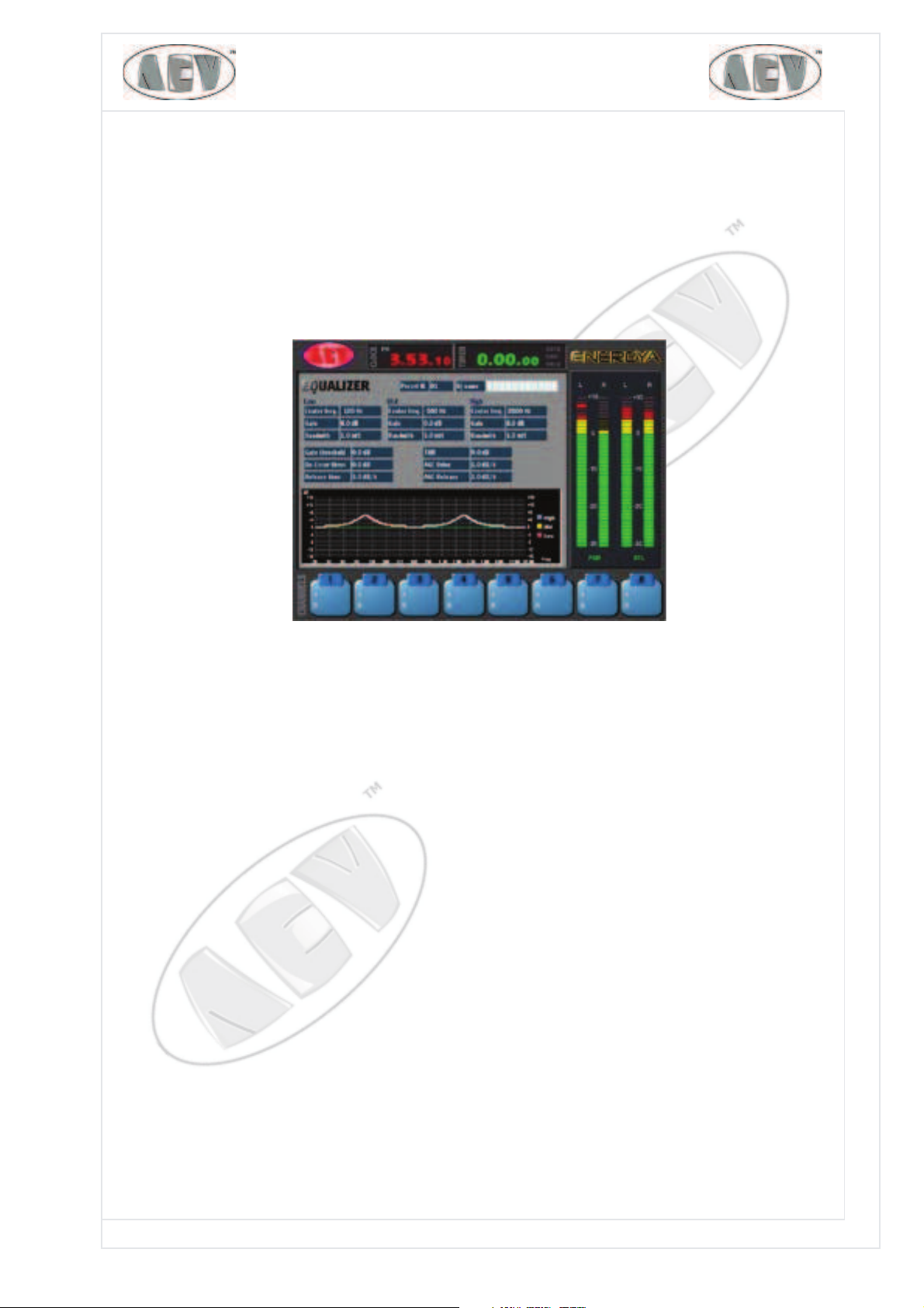
I n t er na l Voice Pr ocessor Se t up
Let's analyse the microphone processor options.
A microphone process curve can be called back and/or modified from this menu.
PRESET N. & DJN AME
These parameters identify the number of the curve associated with a given DJ, up to a maximum
of 30, and the name of the DJ too. Inputting is done, as we explained previously, by using the
Enter and arrow keys. The following parameters are typical of a 3-band microphone processor.
First of all, we shall see what the variation ranges are for each parameter, and we shall then
explain them.
EQUALI ZZATI ON :
Low Band Mid Band High Band
CENTER F. 0.03 ÷ 0.6 kHz0.2÷7.5 kHz 0.4 ÷ 15 kHz
GAIN +/-16dB +/-16dB +/-16dB
BANDWIDTH 0.1 ÷ 5 oct 0.1 ÷ 5 oct 0.1 ÷ 5 oct
DEESSER:
AMOUNT 0% ÷ 100%
RELEASE TIME 1 ÷ 10 dB/sec
MI C COMPRESSI ON:
THR +2 ÷ -8 dB
ATTACK 1 ÷ 20 (1=SLOW, 20=FAST)
AGC RELEASE 1 ÷ +20 dB/s

PAG. 14 EnergiaEnergia
EnergiaEnergia
Energia
Electronic Equipment
Electronic Equipment
Electronic Equipment
AEV S.P.A VI A D E L L A TE C N I C A N.3 I-40050 AR G E L AT O BO L O G N A ITA LY WWW.A E V .N E T WWW.A E V -U S A .C O M E-M A I L : I N F O @A E V .N E T
CEN TER Findicates the band centre and its possible variation range
GAI N indicates the amplification and attenuation quantity to be applied to that given band.
BAN D W I D TH , indicates band-width in octaves.
DE-ESSER: Option enable (ON OFF)
DE-ESSER AM OUNT: value to control the signal when it goes over an internal threshold.
DE-ESSER RELEASE indicates the preset of the release time, i.e. of the speed at which AGC follows
the signal amplitude.
DS M OD E:check filter for the "S"
COMPRESS:Option enable (ON OFF)
THR is the audio level threshold where the processor start working.
COMPRESSOR ATTACK TI ME: sets the compressor tripping time
AGC RELEASE: sets the compressor release time (dB/s)
Line Se t u p
Let's analyse Line input.
Let's see to what the 24 available parameter refer.
LEVEL
Typical adjustment of input level in range -12 ÷ +12 dB
BALANCE
Channel balance adjustment
TYPE
This function enables selection of the Normal operating mode (standard) or of the Telco
operating mode, used for telephone bars - the latter can be assigned to 2 channels only,
one for Telco 1 and one for Telco 2.
MODE
The Left and Right input channels can be controlled with this selection. In stereo mode, the

PAG. 15
EnergiaEnergia
EnergiaEnergia
Energia
Electronic Equipment
Electronic Equipment
Electronic Equipment
AEV S.P.A VI A D E L L A TE C N I C A N.3 I-40050 AR G E L AT O BO L O G N A ITA LY W W W .A E V .N E T WWW.A E V -U S A .C O M E-M A I L : I N F O @A E V .N E T
L and R output channels do not change; in Mono mode, the same mono signal (L+R)/2 is
present on both the L and R outputs; in the LT mode, the same L signal is present on both
L and R outputs; finally, in the RT mode, the same R signal is present on both L and R outputs.
PHASE
This function makes it possible to reverse the phase of a channel with respect to another channel.
PGM
Selects assignment or non-assignment to the Music bus
UTL
Selects assignment or non-assignment to the UTL bus
TELCO1
Selects assignment or non-assignment to the TELCO 1 bus when the channel is in start status. This
function can be activated only if the channel was not defined as Type Telco 1
TELCO2
Selects assignment or non-assignment to the TELCO 2 bus when the channel is in start status. This
function can be activated only if the channel was not defined as Type Telco 2
TALLY1
Enables a stable contact when the channel is in Start status and addressed to the PGM bus.
TALLY2
Enables a stable contact when the channel is in Start status and addressed to the PGM, UTL,
TELCO1 or TELCO2 bus.
MUTE C.ROOM ON START
If ON is activated, and the channel is in Start status, the CONTROL ROOM output is disabled.
MUTE C.STUDI O ON START
If ON is activated, and the channel is in Start status, the CONTROL STUDIO output is disabled.
MUTE CUE SPEAK ON START
If ON is activated, and the channel is in Start status, the CUE speaker output is disabled.
MUTE C.ROOM ON CUE
If ON is activated, and the channel is in Cue status, the CONTROL ROOM output is disabled.
MUTE C.STUDI O ON CUE
If ON is activated, and the channel is in Cue status, the CONTROL STUDIO output is disabled.
MUTE CUE SPEAK ON CUE
If ON is activated, and the channel is in Cue status, the Cue Speaker output is disabled.
MUTE BUSES ON CUE
If ON is activated, and the channel is in Cue status, the PGM, UTL, TELCO 1 and TELCO 2 busses
are disabled, if the channel was on "Start", the key start to flashing.
TI MER RESTART
If it is active, by pressing the channel START button, a restart command is automatically sent to
the Timer, provided the AUTO push-button of the Timer section is active.
FADER AUTO START/ STOP
If it is active, by raising the SLIDER, the channel automatically goes into START status; lowering
the SLIDER, the channel automatically goes into STOP status.
NOECHO ON CMD REMOTE
If active, when a START command is received erxternally, the channel goes into start status.
However, if a "TLC start mode out" command is present, it is not energised. This function is
used if there are devices with pulsed starts/stops all on the same wire: the start's echo

PAG. 16 EnergiaEnergia
EnergiaEnergia
Energia
Electronic Equipment
Electronic Equipment
Electronic Equipment
AEV S.P.A VI A D E L L A TE C N I C A N.3 I-40050 AR G E L AT O BO L O G N A ITA LY WWW.A E V .N E T WWW.A E V -U S A .C O M E-M A I L : I N F O @A E V .N E T
would cause the source to stop. On the contrary, in the OFF mode, the command is sent
back at output too.
MORE
For accessing the remote controls menu.
AES/ EBU Se t u p
We shall now take a look at how the AES/EBU input differs from the Line input.
In addition to the Line input commands we already described, the following commands are available
WORD LENGTH
This is used for selecting the length of the transmission frame - possible values are 16, 20 and 24
bits.
SAM P.RATE
For viewing which frequency of sampling is receive into the digital input.
All the other parameters are identical.
We shall now examine how to set the remote controls by using the MORE push-button available in
all the input menus.
With this menu, you can assign a remote control to a maximum of 16 events These are the
PAG. 17
EnergiaEnergia
EnergiaEnergia
Energia
Electronic Equipment
Electronic Equipment
Electronic Equipment
AEV S.P.A VI A D E L L A TE C N I C A N.3 I-40050 AR G E L AT O BO L O G N A ITA LY W W W .A E V .N E T WWW.A E V -U S A .C O M E-M A I L : I N F O @A E V .N E T
parameters available for selection:
OUT START
This parameter couples one of the 16 available remote controls to the Start event in editing.
The Mode option is available for all remote controls.
MODE
This parameter couples the remote control's mode, which can be any of the following: FI X N C
(normally closed stable contact), Fix NO (normally open stable contact), PULS N C (normally
closed pulsed contact), PULS N O (normally open pulsed contact). The Pulse
Time parameter is also available for pulse output remote controls.
PULSE TI ME
In the Puls mode, this parameter couples the pulse duration time (in seconds).
OUT STOP
This parameter couples one of the 16 available remote controls to the Stop event in editing.
INSTART
This parameter makes it possible to combine one of the 16 available remote controls with the Start
function. The command received from the coupled photocoupler starts the channel.
INSTOP
This parameter makes it possible to combine one of the 16 available remote controls with the Stop
function. The command received from the associated photocoupler starts the channel.
INCUE
This parameter makes it possible to combine one of the 16 available remote controls with the Cue
function. The command received from the associated photocoupler starts the channel.
INTBK
This parameter makes it possible to combine one of the 16 available remote controls with the
TalkBack function.
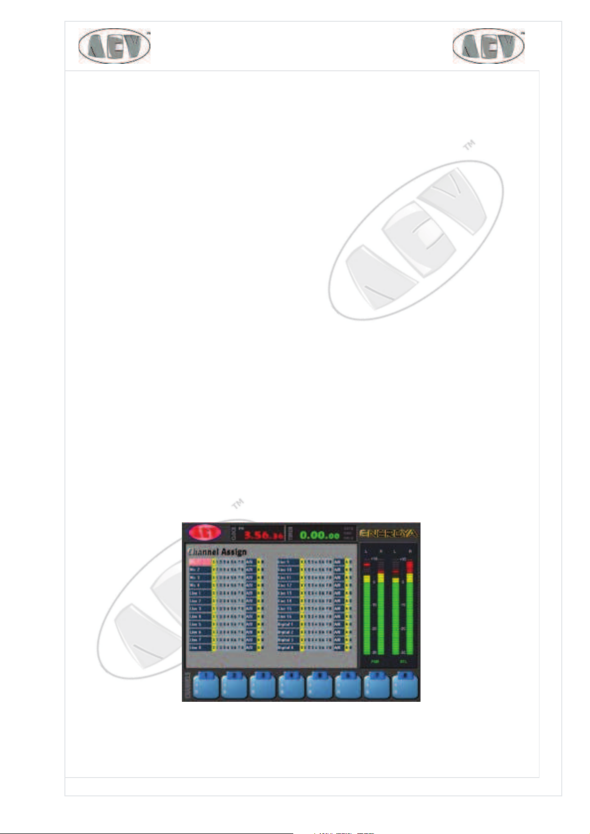
Cha nne l Assign
This menu allowed to associate the input (configured before) to the slider.
By using the same editing system, you can select up to 16 sources (8 for channel A and 8 for
channels B).

PAG. 18 EnergiaEnergia
EnergiaEnergia
Energia
Electronic Equipment
Electronic Equipment
Electronic Equipment
AEV S.P.A VI A D E L L A TE C N I C A N.3 I-40050 AR G E L AT O BO L O G N A ITA LY WWW.A E V .N E T WWW.A E V -U S A .C O M E-M A I L : I N F O @A E V .N E T
Sy st e m Se t u p
LANGUAGE
For selecting a language from among those available: English, Italian or Spanish
TCPIPADDRESS
This is used for setting the IP address of the Energya mixer, which is necessary for it to be inserted into the
network together with other devices, such as PCs, printers, etc - it usually observes the following ranges:
RFC1918 10.0.0.0 ÷ 10.255.255.255, 172.16.0.0 ÷ 172.31.255.255, 192.168.0.0 ÷ 192.168.255.255
TCPIPNETMASK
For setting the address of the Netmask, usually of the following type: 255.255.255.0
FADER REFERENCE
Enables to changed the slider scale
KLOCK MODE
Select the clock format 12H or 24H
TALLY1 MOD E / TALLY2 M ODE
Used for selecting flashing or steady output.
WORD CLOCK SYNC
This is an I/O for synchronising the digital frame by exploiting word synchronism (L/R clock)
AES/ EBU SYNC
An I/O used for synchronising the digital frame by exploiting an AES/EBU signal
SYNCRO CLOCK
For synchronising the Energya clock directly with atomic clocks transmitting via information
networks, using the methods specified in Netw ork Tim e Prot ocol
SYNCRO SERVER
Not yet available
ADDI TI ONAL TELCO 3 ,4
Additional TELCO 3,4 function allows to have 4 TELCO busses; see forwrd in the section" 4 TELCO
busses"
DEFAULT PRESET
Delete the Preset online without change the memory
GPI - GPO
For changeover to the function keys configuration menu
CURSOR BLI NK
Select the blink option for the cursor
PAG. 19
EnergiaEnergia
EnergiaEnergia
Energia
Electronic Equipment
Electronic Equipment
Electronic Equipment
AEV S.P.A VI A D E L L A TE C N I C A N.3 I-40050 AR G E L AT O BO L O G N A ITA LY W W W .A E V .N E T WWW.A E V -U S A .C O M E-M A I L : I N F O @A E V .N E T
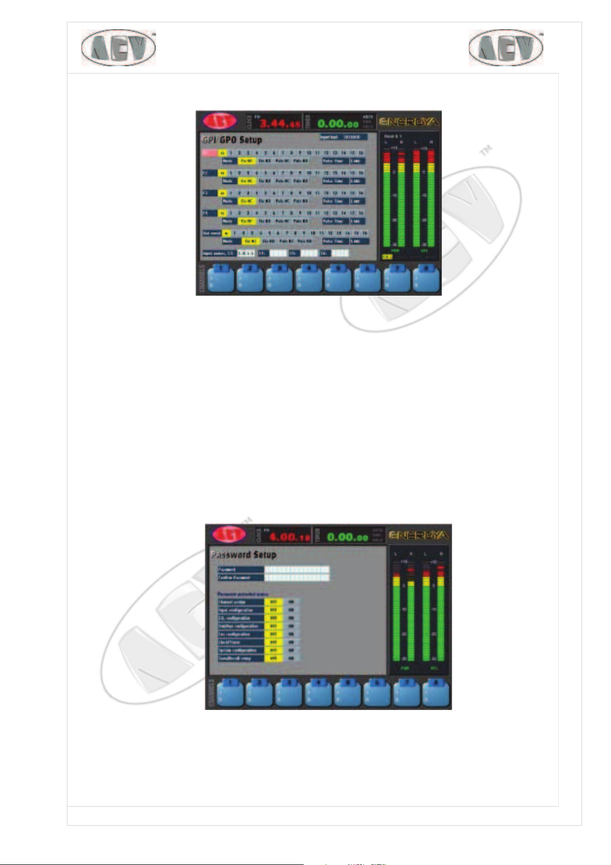
GPI / GPO Se t u p
There are four sections referring to function keys F1, F2, F3 and F4. Similarly, there is a
Out event section, which refers to an event - e.g. arrival of an external command -
pressing of certain keys or sets of keys ,etc. In the Input Name section it is necessary
to assign a name (max 4 char) to control the input photocouplers 13, 14, 15 and 16
status (ie incoming phone call).
We shall now take a look at an example for setting F2.
Using the editing method we described previously, you select one of the 16 available
photocouplers: use the MO D E option to select type of contact, FI X (stable) or PU LS
(pulsed), and type of operation N O (normally open) or NC (normally closed). The PU LSE
TI M E option enables us to set pulse time in seconds for PU LS N O or PU LS N C.
Pa ssw or d Se t u p
You can enter a password with this option. When enabled, it must be inserted in order to access
protected menus. To select, shift to ON the push-button for the highlighted menu to be
protected.
PAG. 20 EnergiaEnergia
EnergiaEnergia
Energia
Electronic Equipment
Electronic Equipment
Electronic Equipment
AEV S.P.A VI A D E L L A TE C N I C A N.3 I-40050 AR G E L AT O BO L O G N A ITA LY WWW.A E V .N E T WWW.A E V -U S A .C O M E-M A I L : I N F O @A E V .N E T
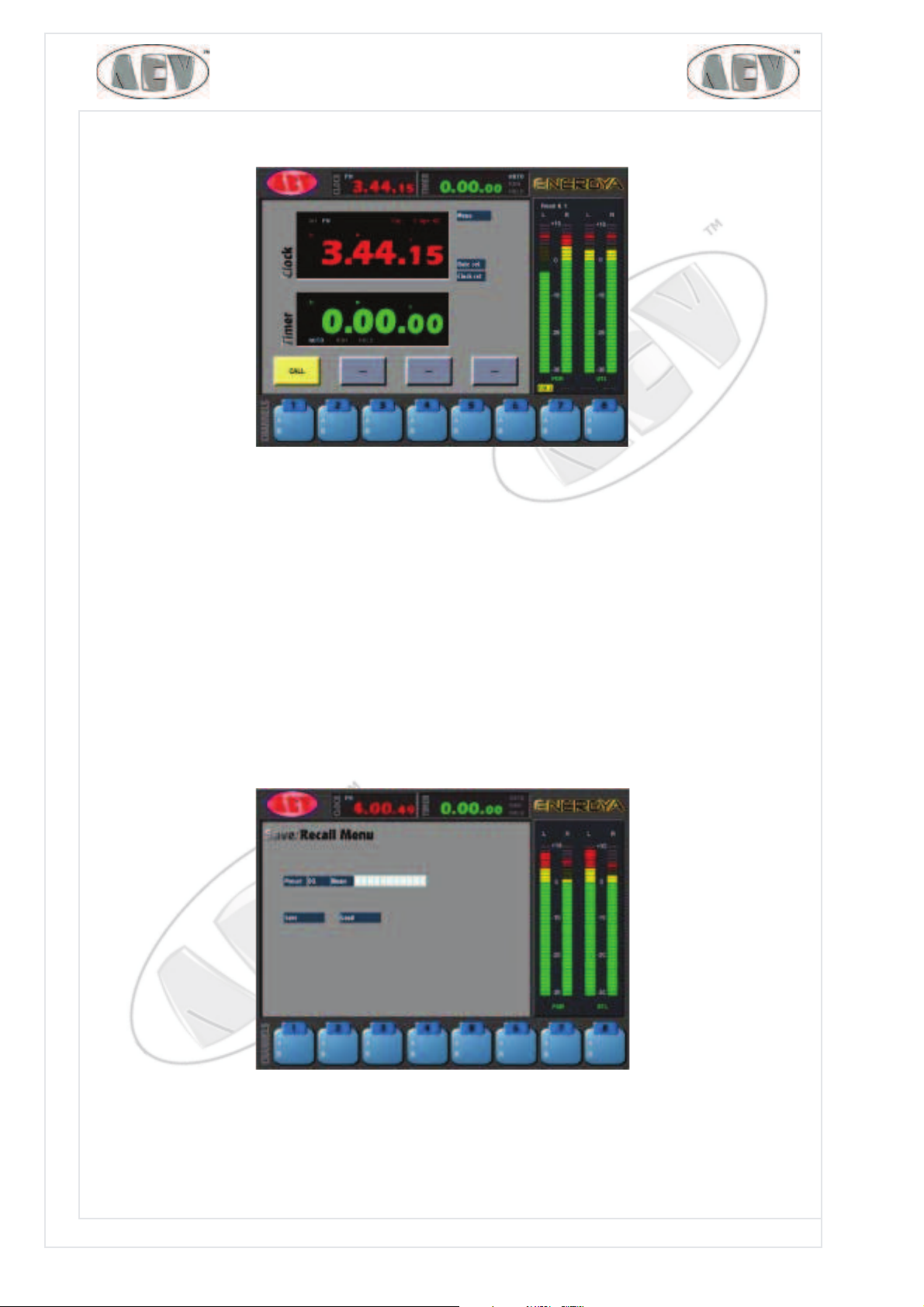
Clock Tim e r se t up
The following options are available in addition to return to main menu:
DATE SET
For setting correct date values.
CLK SET
For setting correct time values.
The Timer receives commands strictly from the mixer push-buttons.
Under the Timer window four buttons are available to display the status of the 13, 14, 15 and 16
photocoupler inputs. See GPI/GPO setup.
SAV E / RECALL Se t up
Use this simple menu to LOAD or SAVE one of the 64 PRESETS associated with a NAM E. Whenever
you save or load, you are prompted to confirm whether you wish to continue with the operation.

PAG. 21
EnergiaEnergia
EnergiaEnergia
Energia
Electronic Equipment
Electronic Equipment
Electronic Equipment
AEV S.P.A VI A D E L L A TE C N I C A N.3 I-40050 AR G E L AT O BO L O G N A ITA LY W W W .A E V .N E T WWW.A E V -U S A .C O M E-M A I L : I N F O @A E V .N E T
Cu e Se t up
The pre-listening menu has 4 options. From this menu, you can define which signal to display on
the CUE viewing bar.
CUE METER SELECTI ON
This is used for selecting which of the available signals UTL, TELCO1, TELCO2, EXT1, EXT2)
should be displayed on right ledmeter, unless a Cue push-button was selected.
TALK BACK TO TELCO 1
For selecting whether to send the intercom microphone signal of the mixer to the Telco 1 bus,
when is activate the "TB" key on the mixer.
TALK BACK TO TELCO 2
For selecting whether to send the intercom microphone signal of the mixer to the Telco 2 bus,
when is activate the "TB" key on the mixer.
TALK BACK TO CON TROL STUD I O
For selecting whether to send the intercom microphone signal of the mixer to the Control Studio
output, when is activate the "TB" key on the mixer.
CUE SPEAKER
Use this to select which of the available signals (PGM, UTL, EXT1, EXT2, CUE) to send to
the mixer speaker.
SPK MUTE ON TALKBACK
For selecting whether to disable the speaker when using TalkBack.
CUE I N TERLOCK
This is used for enabling the function whereby, when a Cue is pressed, the previously active one
is de-selected automatically.

PAG. 22 EnergiaEnergia
EnergiaEnergia
Energia
Electronic Equipment
Electronic Equipment
Electronic Equipment
AEV S.P.A VI A D E L L A TE C N I C A N.3 I-40050 AR G E L AT O BO L O G N A ITA LY WWW.A E V .N E T WWW.A E V -U S A .C O M E-M A I L : I N F O @A E V .N E T
OUT/ AUX Con figu r at ion
The mixer has the following inputs and outputs:
- two external inputs EXT 1 and 2 analog inputs
- two PGM analog outputs in parallel
- one PGM digital output
- two UTL analog outputs in parallel
- one UTL digital output
- two analog Telco (1 and 2) outputs
- two fixed digital 48 kHz Telco (1 and 2) outputs
- a Mono output
EXT 1 LEV
Adjustment of auxiliary input level Ext1 - this control is in the range -12 to +12 dB
EXT 2 LEV
Adjustment of auxiliary input level Ext2 - this control is in the range -12 to +12 dB
PGM LEV
Adjustment of the PGM output signal in range 0 ÷ +12 dB
UTL LEV
Adjustment of the level of output signal UTL in range 0 ÷ +12 dB
TELCO 1 LEV
Adjustment of the level of the Telco 1 output signal in range 1 ÷ +12 dB
TELCO 2 LEV
Adjustment of the level of the Telco 2 output signal in range 1 ÷ +12 dB
MONO LEV
Adjustment of the level of the PGM output signal in range 0 ÷ +12 dB
MONO ASSI GN
For selecting which bus to send to the mono output - possible options: PGM, UTL, TB (local
microphone)
You access the following menu by selecting the DI GI TAL SETUP push-button.

PAG. 23
EnergiaEnergia
EnergiaEnergia
Energia
Electronic Equipment
Electronic Equipment
Electronic Equipment
AEV S.P.A VI A D E L L A TE C N I C A N.3 I-40050 AR G E L AT O BO L O G N A ITA LY W W W .A E V .N E T WWW.A E V -U S A .C O M E-M A I L : I N F O @A E V .N E T
SAMPLE RATE
For selecting the sample rate at the PGM digital output - possible configurations: 32, 44.1, 48,
96 KHz
WORD LENGHT
For selecting the transmission frame length from among the following available values: 16, 20, 24
bit
SAMPLE RATE
For selecting the sample rate at the PGM digital output - possible configurations: 32, 44.1,
48, 96 KHz
WORD LENGTH
For selecting the transmission frame length from among the following available values: 16, 20, 24
bit
WO R D LEN GT H can be selected only with T ELCO 1 and 2.
Direct com m ands
Commands linked to a specific push-button on the mixer, causing an immediate action.
Dir ect com m a nds : I n put ch ann els se ct ion
The following are present on each channel:
SEL
For deciding which section of the channel to activate (A or B). A and B can be selected only if
the channel is in STOP state - selection causes the relevant LED to light up automatically.
EDI T
When the EDIT key is pressed, the display shows all the parameters for that channel (CHANNEL
SETUP)
CUE
The following actions occur when a CUE key is pressed: the input signal of that channel is
sent to the CUE bus and is displayed on the right-hand level meter. Moreover, this selection
causes the relevant LED to light up automatically. This signal will replace the previously
selected signal on the C.Room, CUE speaker and headset outputs. Simultaneously, the key
for the channel being listed to in C.Room will change from steady light to flashing.

PAG. 24 EnergiaEnergia
EnergiaEnergia
Energia
Electronic Equipment
Electronic Equipment
Electronic Equipment
AEV S.P.A VI A D E L L A TE C N I C A N.3 I-40050 AR G E L AT O BO L O G N A ITA LY WWW.A E V .N E T WWW.A E V -U S A .C O M E-M A I L : I N F O @A E V .N E T
START
When the START key is pressed, the following actions occur: the channel input signal is sent
to the PGM and/or UTL busses, if previously selected; the CUE function is disabled if it had
been enabled and any command that may have been associated with it is activated (see Tlc
setup).
STOP
When the STOP key is pressed, the following actions occur: the channel input signal is no longer
sent to the PGM and/or UTL busses, if they had been selected. Telco 1 and Telco 2 busses are
not influenced by the STOP. If previously enabled, the CUE function is disabled, and any command
that may have been associated with it is activated (see Tlc setup).
Dir ect com m a nds: Cont rol Room Sect ion
The level of the Control Room output can be varied with the C.Room potentiometer on the panel.
EXT1
When the EXT1 key is pressed, the following actions occur: the EXT1 input signal is sent to the
Control Room output, and the function previously set on the Control Room bar is disabled.
EXT2
When the EXT2 key is pressed, the following actions occur: the EXT2 input signal is sent to the
Control Room output, and the function previously set on the Control Room bar is disabled.
PGM
When the PGM key is pressed, the following actions occur: the PGM input signal is sent to the
Control Room output, and the function previously set on the Control Room bar is disabled.
UTL
When the UTL key is pressed, the following actions occur: the UTL input signal is sent to the
Control Room output, and the function previously set on the Control Room bar is disabled.
D ir e ct com m a nds : Con t r ol St udio Se ct ion
The level of the Control Studio output can be varied with the C.Studio potentiometer on the
panel.
EXT1
When the EXT1 key is pressed, the following actions occur: the EXT1 input signal is sent to the
Control Studio output, and the function previously set on the Control Studio bus is disabled.
EXT2
When the EXT2 key is pressed, the following actions occur: the EXT2 input signal is sent to the
Control Studio output, and the function previously set on the Control Studio bus is disabled.
PGM
When the PGM key is pressed, the following actions occur: the PGM input signal is sent to the
Control Studio output, and the function previously set on the Control Studio bus is disabled.
UTL
When the UTL key is pressed, the following actions occur: the UTL input signal is sent to the
Control Studio output, and the function previously set on the Control Studio bus is disabled.
CUE
When the CUE key is pressed, the following actions occur: the signal on the CUE bus is sent to
the Control Studio output, and the function previously set on the Control Studio bus is disabled.

PAG. 25
EnergiaEnergia
EnergiaEnergia
Energia
Electronic Equipment
Electronic Equipment
Electronic Equipment
AEV S.P.A VI A D E L L A TE C N I C A N.3 I-40050 AR G E L AT O BO L O G N A ITA LY W W W .A E V .N E T WWW.A E V -U S A .C O M E-M A I L : I N F O @A E V .N E T
TB
When the TB key (Talkback) is pressed, the signal of the service microphone is sent to the busses
selected in the "AUX In/Out Setup" menu.
BEW ARE: the Microphone signal replaces the signal which had up to then been directed to the pre-
selected outputs. When the TB key is released, everything returns to its previous state.
PRIVATE communication, using a telephone hybrid (AEV mod. ITB302) if any, can be performed
only by using the TB microphone signal, with "TELCO" channel in STOP and CUE selected.
D ir e ct co m m a nds: H e a dse t se ct io n
The level of the Headset output can be varied with the "Headset" potentiometer on the panel.
The signal directed to the Control Room is usually sent to the
headset output. Whenever one of the CUE keys is activated, CUE replaces the Control
Room signal. There may be exceptions depending on activation of the DIM and SPLIT
functions.
DI M
If activated, it directs the signal on the CUE bus to the L and R headset output,
and adds it to the signal present on the bus selected by the Control Room
section - the latter is attenuated.
SPLI T
If activated, it directs the signal on the CUE bus [(L+R)/2] to the left ear-piece
of the headset, and directs the signal on the bus selected in the Control Room
section [(L+R)/2] to the right ear-piece.
DI M+ SPLI T
The two functions can also be combined, so that the CUE signal is on the
left ear-piece of the headset and the signal selected by the Control Room
section is on the right side, attenuated.
D ir e ct co m m a nds: CU E Sp e ak e r Se ct ion
VOLUME SPEAKER
Used for adjusting the volume of the speaker cabinet on the mixer. The selection of what signal
to send to Headphone is operated by "CUE Configuration" menu.
Direct com m ands: Tim er section
The clock/timer selection commands are also located on the console - we shall see them right
away on the "tim e r/ Clock setup" page.
AUTO
If active, it enables automatic RESTART when START is pressed on a channel with the "timer restart"
function enabled. This swich will be visible in the square panel calles "Timer" of the menu.
S/ S ( RUN)
Enables manual starting and stopping of the timer. If you press it once, counting is enabled, if
you press it again, the count is stopped. This swich will be visible in the square panel calles "Timer"
of the menu.
RESET
Used for resetting the timer: if the count was stopped, the timer is reset, if it was not stopped,
it restarts automatically after being reset.
HOLD
Use this to view a partial time without shutting down the timer. If you press it again, it
displays the current count again, or it displays the total if the count had been stopped while
the partial time was being viewed. This swich will be visible in the square panel calles "Timer" of
the menu.
Table of contents
Other AEV Music Mixer manuals


