aevit SMART-SHIFT User manual


SMART-SHIFT INSTALLATION
TABLE OF CONTENTS
1. OVERVIEW 1
2. INSTALLATION 2
2.1 SHIFT CABLE INSTALLATION 2
2.2 MOUNTING THE SMARTSHIFT ACTUATOR BRACKET 10
2.3 MOUNTING CONTROLLER AND TOUCHPAD 11
2.4 ELECTRICAL CONNECTIONS 11
3. CALIBRATION 15
SMART-SHIFT INSTALLATION
The EMC Smart-Shift answers all of the“shifting” needs of the individual, the installing dealer, and the driver
rehabilitation professional. This system can be installed in almost any vehicle equipped with a cable actuated
automatic transmission to remotely operate the vehicle’s shifting functions. The Smart-Shift is operated by the
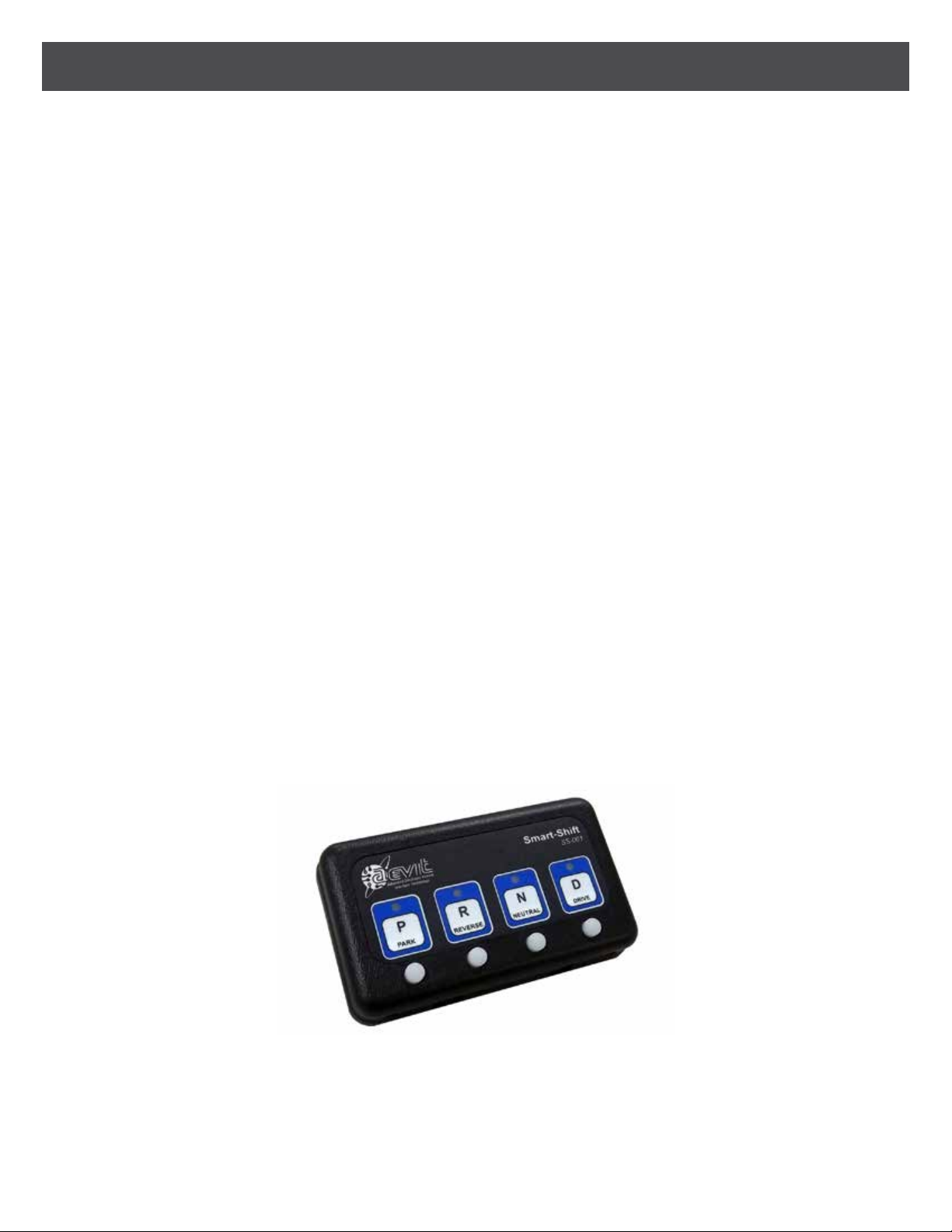
four illuminated tactile buttons on the front of a small (5.5” x 3.25” x 1”) touchpad. Each button is positioned
below the icon representing the corresponding gear which it operates. Each icon has an LED to signal when
the actuator has reached the programmed position.
The Smart-Shift incorporates positional feedback so that the actuator can be automatically positioned in up to
seven selector choices; Park, Reverse, Neutral, Drive, Drive3, Drive2, and Drive1 (Drive3, 2, & 1 are not available
for all vehicles). When the vehicle is in Park and any other key is depressed, the actuator will move the shifter
cable to the selected gear, stop automatically and illuminate the LED indicator. No more missed gears or wait-
ing in trac for the actuator to slowly move. In addition, the multifunctional “D” button can be programmed
for up to four dierent Drive positions (Drive, Drive3, Drive2 & Drive1).
Operation of the system is quite simple. While the vehicle’s ignition is ON and the brakes are applied, press any
of the four buttons to move the vehicle’s transmission to the selected gear. To activate Drive 3, 2 & 1 simply
press the Drive key while in Drive. Each time the key is depressed it will cycle through each position. The “D”
LED will continually ash while you are in Drives 3, 2 & 1, with each one ashing at a dierent rate. To exit any
of the low Drives, just depress any key, and the vehicle’s transmission will be switched to that position. The
Smart Shift requires two inputs for the system to operate; 1) the ignition of the vehicle must be “On”and 2) the
brakes must be applied.
The Smart-Shift includes a Touchpad, Actuator (and mounting bracket), Controller Module, Vehicle Interface
cord, a telco cord, and an Universal installation kit. The actuator will need to be mounted in such a way that
it will interface with the vehicle’s transmission shift cable. This can be done by mounting the actuator and
bracket to the vehicle to provide solid connection that the transmission cable will reach. The Universal instal-
lation kit includes additional, smaller mounting brackets for mounting the actuator to the vehicle along with
hardware and a cable bracket to secure the tranmission shift cable to the actuator.
M11
1. OVERVIEW
1

SMART-SHIFT INSTALLATION
Mounting the actuator to the vehicle’s shift cable and than to the vehicle are the most important parts of the
entire installation process. The actuator can position itself accurately to within 1/32”of travel. If the shift cable
is not positioned mechanically correct relative to the actuator, the shift positions will vary with each applica-
tion due to freeplay in your mechanical installation. For this reason, EMC supplies the Smart-Shift mounting
bracket preassembled to the actuator. Determine the method for attaching the shift cable rst, followed by
securing the actuator mounting the bracket to the vehicle.
THE ACTUATOR MOUNTED TO THE SMARTSHIFT ACTUATOR BRACKET
Refer to FIGURE 1 below to understand how the actuator is attached to the actuator mounting bracket. This
method is the same for all vehicles. The only changes that occur from one vehicle to another is the design of
the Cable Bracket and the hardware for attaching the shift cable to the Nose Cone. Refer to the remainder of
this section for the Nose Cone and Cable Brackets instructions for some common EMC vehicles.
M11
2. INSTALLATION
2
2.1 SHIFT CABLE INSTALLATION
SMART-SHIFT INSTALLATION
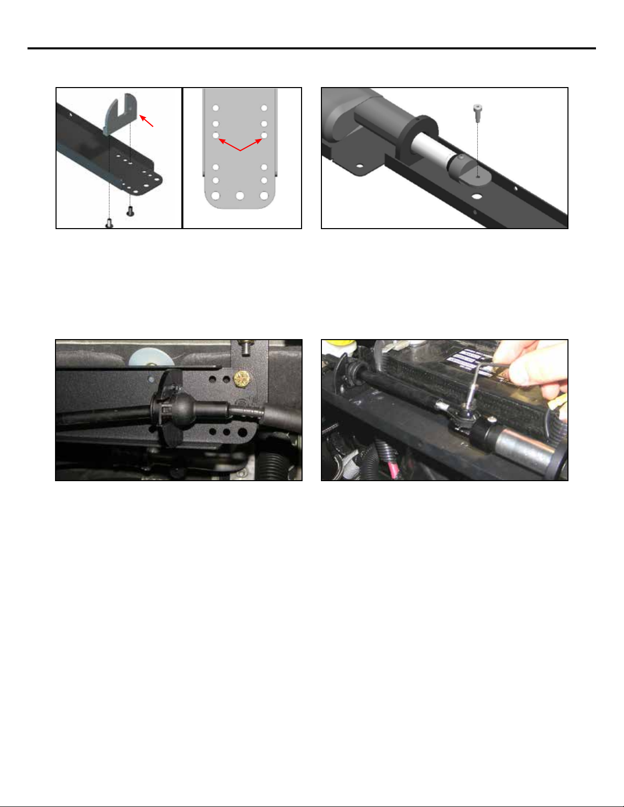
Attach the Cable Bracket (included in KIT-SS-ASSY-
08C) to the end of the Smart Shift bracket in the
location shown in the gures above. The at side of
the bracket should be facing away from the actuator.
Secure this bracket using the (2) provided #10-32 x
3/8” button head screws and a small amount of Blue
Loctite®.
2008+
CHRYSLER /
DODGE
CABLE
BRACKET
Carefully tap the hole in the Nose Cone to #8-32.
Verify the #8-32 x 3/8” shoulder screw (included in
KIT-SS-ASSY-08C) will thread properly into the Nose
Cone. Do not install the shoulder screw at this time.
CHRYSLER TOWN & COUNTRY / DODGE GRAND CARAVAN 2008+
After calibration (see Section 3), verify the cable is
in Park. Insert the shoulder screw through the OEM
cable end and into the Nose Cone as shown, using a
small amount of Blue Loctite®.
Carefully insert the OEM shifter cable sleeve into the
Cable Bracket until the plastic ear snaps into the hole
in the Cable Bracket.
3
SMART-SHIFT INSTALLATION
TOYOTA SIENNA 20042010
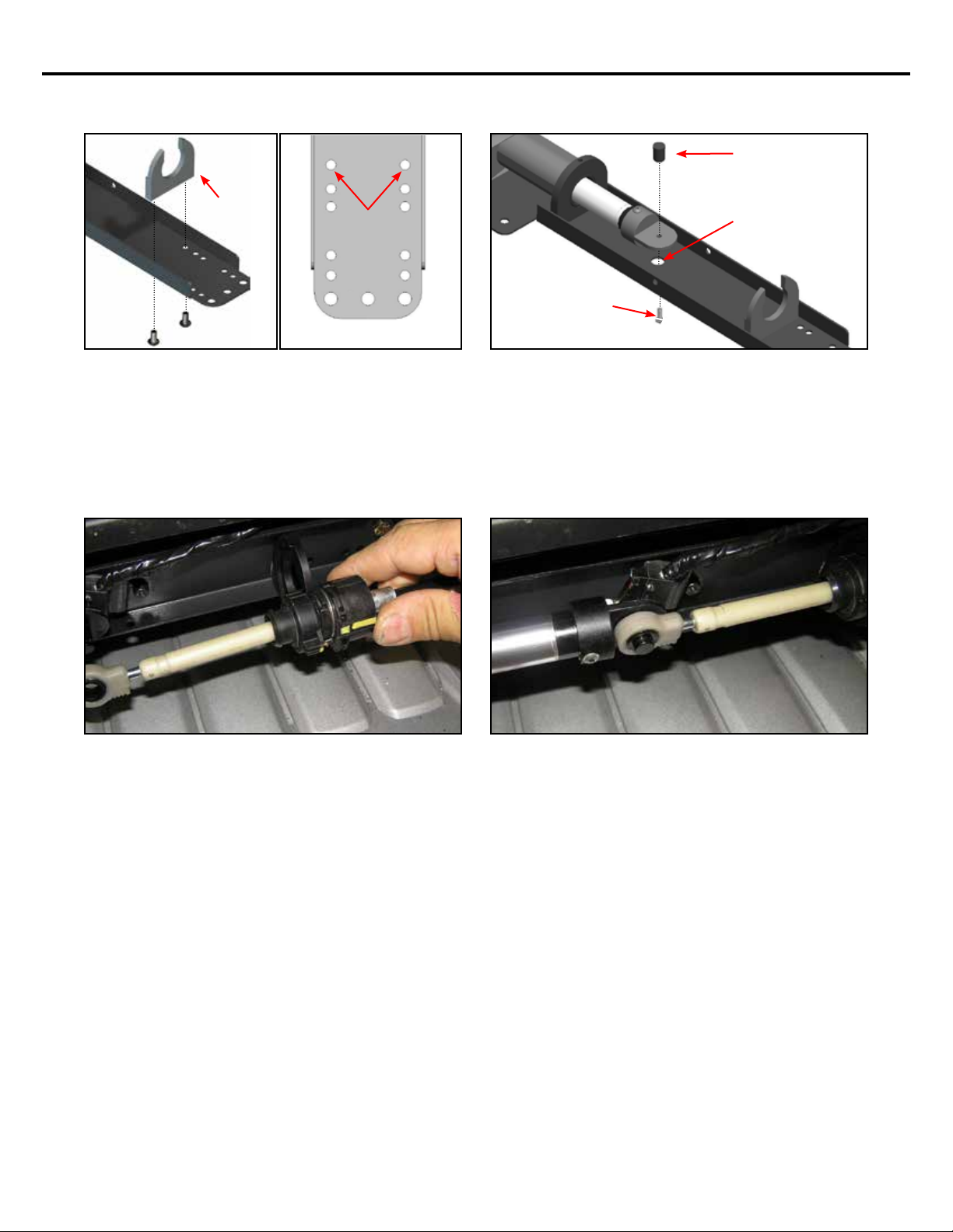
Attach the cable bracket (included in KIT-SS-ASSY-
04T) to the end of the Smart Shift bracket in the
location shown in the gures above. The at side of
the bracket should be facing away from the actuator.
Secure this bracket using the (2) provided #10-32 x
3/8” button head screws and a small amount of Blue
Loctite®.
2004-2010
TOYOTA SIENNA
CABLE
BRACKET
Attach the Smart-Shift pin (included in KIT-SS-ASSY-
04T) to the Nose Cone using the supplied #6-32 x
3/8” button head screw and Blue Loctite®. Hint: Use
the 3/8” hole directly beneath the nose cone to gain
access to the underside of the nose cone in order to
insert and tighten the screw as shown.
SMART SHIFT
PIN
USE THE 3/8” HOLE
IN THE BRACKET TO
GAIN ACCESS TO THE
UNDERSIDE OF THE
NOSE CONE.
#6-32 x 3/8” BUTTON
HEAD SCREW
After calibration (see Section 3), verify that the cable
is in Park. Snap the shift cable over the pin on the
Nose Cone.
Secure the shift cable to the Smart Shift by sliding
the end of the OEM cable onto the Cable Bracket.
4

SMART-SHIFT INSTALLATION
TOYOTA SIENNA 20112019
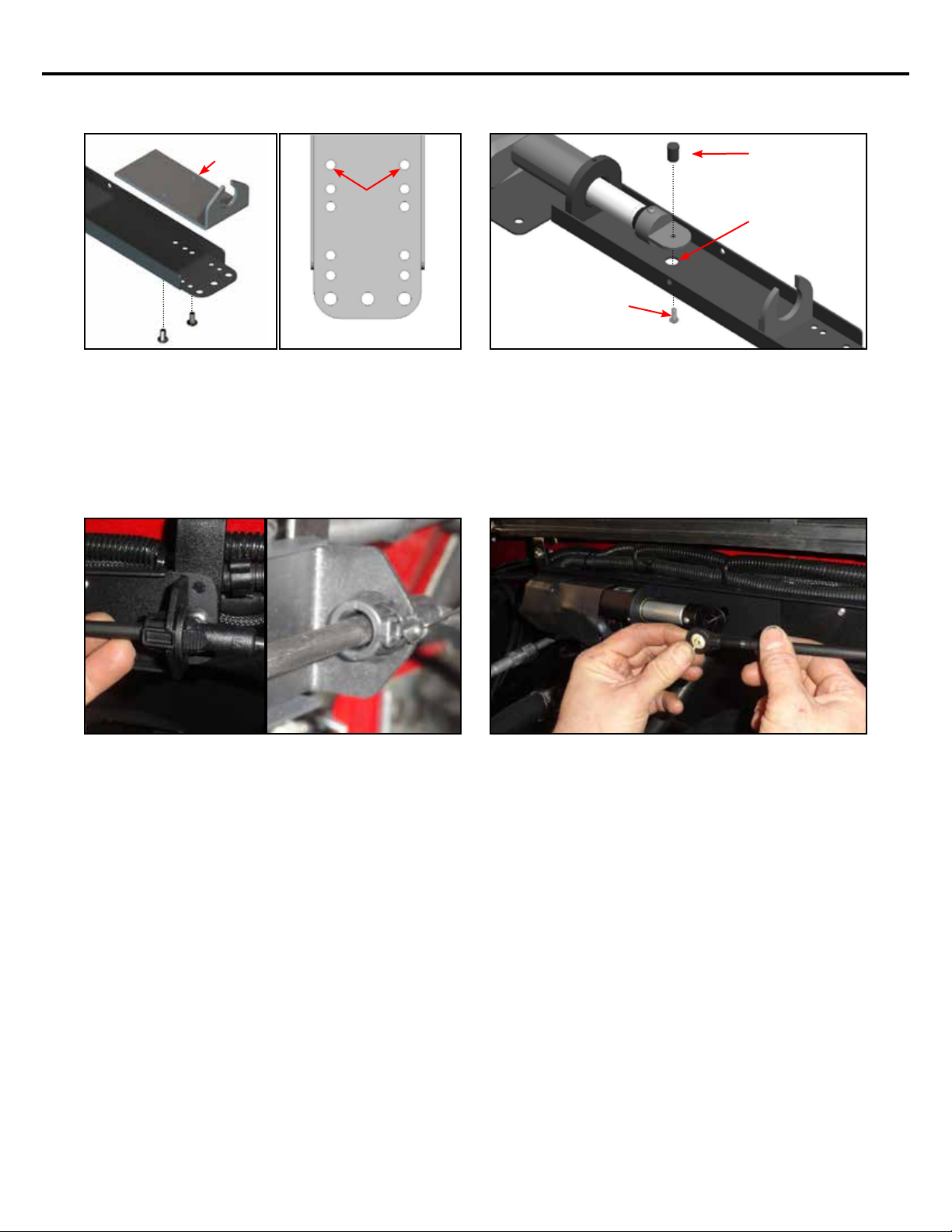
Attach the cable bracket (included in KIT-SS-ASSY-
04T) to the end of the Smart Shift bracket in the
location shown in the gures above. The at side of
the bracket should be facing away from the actuator.
Secure this bracket using the (2) provided #10-32 x
3/8” button head screws and a small amount of Blue
Loctite®.
2011-2019
TOYOTA
SIENNA
CABLE
BRACKET
Attach the Smart-Shift pin (included in KIT-SS-ASSY-
04T) to the Nose Cone using the supplied #6-32 x
3/8” button head screw and Blue Loctite®. Hint: Use
the 3/8” hole directly beneath the nose cone to gain
access to the underside of the nose cone in order to
insert and tighten the screw as shown.
SMART SHIFT
PIN
USE THE 3/8” HOLE
IN THE BRACKET TO
GAIN ACCESS TO THE
UNDERSIDE OF THE
NOSE CONE.
#6-32 x 3/8” BUTTON
HEAD SCREW
After calibration (see Section 3), verify that the ve-
hicle is in Park. Snap the shift cable over the pin on
the Nose Cone.
Secure the shift cable to the Smart Shift by sliding
the end of the OEM cable onto the Cable Bracket.
5

SMART-SHIFT INSTALLATION
HONDA ODYSSEY 20082010
After calibration (see Section 3), verify that the
vehicle is in Park. The shift cable should t into the
OEM cable connector that is already mounted on
the Smart Shift Nose Cone. Once in place, secure the
cable to the connector by sliding the retaining clip
over the OEM cable and sliding the lock over the
retaining clip.
Attach the Cable Bracket (included in KIT-SS-ASSY-
04T) to the end of the Smart Shift bracket in the
location shown in the gures above. The at side of
the bracket should be facing away from the actuator.
Secure this bracket using the (2) provided #10-32 x
3/8” button head screws and a small amount of Blue
Loctite®.
2008-2010 HONDA
ODYSSEY
CABLE
BRACKET
Insert the Smart-Shift pin (included in KIT-SS-ASSY-
04T) through the OEM shift cable connector. Using
the provided #6-32 x 3/8”button head screw, attach
the pin to the actuator Nose Cone as shown using a
small amount of Blue Loctite®.
OEM shift cable connector
Secure the shift cable to the Smart Shift by sliding
the end of the OEM cable onto the Cable Bracket and
rotating.
OEM Shift Cable
Retaining Clip Retaining Clip Lock
OEM Shift Cable Con-
nector
Smart Shift pin
6

SMART-SHIFT INSTALLATION
HONDA ODYSSEY 20112017
After calibration (see Section 3), verify that the
vehicle is in Park. The shift cable should be secured
to the Nose Cone using the 5/16”x 3/4” long button
head bolt and 5/16” lock nut.
Secure the shift cable to the Smart Shift by sliding
the end of the OEM cable onto the Cable Bracket and
rotating.
Attach the Cable Bracket (included in KIT-SS-ASSY-
04T) to the end of the Smart Shift bracket in the
location shown in the gures above. The at side of
the bracket should be facing away from the actuator.
Secure this bracket using the (2) provided #10-32 x
3/8” button head screws and a small amount of Blue
Loctite®.
2011-2017
HONDA ODYSSEY
CABLE
BRACKET
Drill out the nose cone hole to 5/16”. Using a 5/16” x
3/4” long button head bolt and 5/16” lock nut, test
t the OEM shifter cable to the to the actuator Nose
Cone as shown. Hint: Use the 3/8”hole directly be-
neath the Nose Cone to gain access to the underside
of the Nose Cone in order to insert and tighten the
screw as shown.
OEM shift cable connector
7
SMART-SHIFT INSTALLATION
GM SILVERADO / SIERRA 20152018 & 2019 2500 only
After calibration (see Section 3), verify that the ve-
hicle is in Park. Press the shift cable over the pin on
the Nose Cone.
Attach the Cable Bracket (included in KIT-SS-ASSY-
05M) to the end of the Smart Shift bracket in the
location shown in the gures above. Secure this
bracket using the (2) provided #10-32 x 3/8”button
head screws and a small amount of Blue Loctite®.
2015-2019
SILVERADO /
SIERRA
CABLE
BRACKET
Attach the Smart-Shift pin (included in KIT-SS-ASSY-
05M) to the nose cone using the supplied #6-32 x
3/8” button head screw and Blue Loctite®. Hint: Use
the 3/8” hole directly beneath the Nose Cone to gain
access to the underside of the Nose Cone in order to
insert and tighten the screw as shown.
SMART SHIFT
PIN
USE THE 3/8” HOLE
IN THE BRACKET TO
GAIN ACCESS TO THE
UNDERSIDE OF THE
NOSE CONE.
#6-32 x 3/8” BUTTON
HEAD SCREW
Slide the OEM shift cable through the Smart Shift
cable bracket. It will snap in place. Secure the OEM
shift cable to the Smart Shift Cable Bracket by sliding
a zip tie around the clip, underneath the tabs, so
they cannot be compressed or slid out of the Cable
Bracket.
8

SMART-SHIFT INSTALLATION
GM SILVERADO / SIERRA 2019 1500 only2020
After calibration (see Section 3), verify that the
vehicle is in Park. Secure the shift cable to the Nose
Cone using the OEM preassembled hardware and a
small amount of Blue Loctite®.
2020
SILVERADO /
SIERRA
Attach the Cable Bracket (included in KIT-SS-ASSY-
19S) to the end of the Smart Shift bracket in the loca-
tion shown in the gures above. Notch the side of
the Smart Shift bracket. Secure this bracket using the
(2) provided #10-32 x 3/8”button head screws and a
small amount of Blue Loctite®.
CABLE
BRACKET
NOTCH
SMART-SHIFT
BRACKET
The OEM shift cable has an M6 screw preassembled
to it. This means the Smart Shift Nose Cone must be
drilled and tapped to M6 to accept it.
DRILL & TAP
FOR M6 SCREW
Slide the OEM shift cable over the Smart Shift cable
bracket. Secure the OEM shift cable to the Smart
Shift Cable Bracket with the preassembled OEM
hardware and a small amount of Blue Loctite®.
9

SMART-SHIFT INSTALLATION
Each vehicle is dierent, depending on the vehicle type, amount of body lift and length of the shift cable.
Start by pulling the shift cable into the engine bay and seeing where it will reach without contacting anything
hot or needing sharp bends.
More often than not, the best location to mount the actuator bracket is above the engine on the wiper tray or
lower cowl panel. Both ends of the bracket must be attached to something rigid, not something connected
to the motor where there is ex. Some vehicles have threaded studs for hoses or wire looms that the actuator
bracket can be hung from. EMC includes small steel brackets that can be bent or drilled to hold either end of
the actuator bracket. Rivnuts or thru-bolts are also options.
Below are pictures of installed actuator brackets showing possible attachment methods.
Once securely attached, loop the shift cable around and over parts as needed to avoid kinks and hot surfaces.
P-clamp it periodically to hold it in place. Route the actuator harness back into the cabin through an open
grommet or the through the hole used for the shift cable. Seal around the harness to prevent water and fumes
from entering back into the cabin.
2.2 MOUNTING THE SMARTSHIFT ACTUATOR BRACKET
10

SMART-SHIFT INSTALLATION
OTHER APPLICATIONS
If your particular vehicle uses a cable operated shift mechanism, or a mechanical “rod style”, one of the bracket
kits can likely be modied to t your application, or you can fabricate your own. The actuator has a total stroke
of 2-1/4”. You must weld or bolt a bracket to the shift arm on the transmission such that the arc of travel from
Park to Low gear is approximately 2-1/4”. This will be the connection point of the actuator. Other optional
mounting techniques could involve purchasing a Ford or Chrysler shift cable and adapting it to your particular
vehicle. You could also mount the actuator inside the vehicle with this sort of cable control. Feel free to contact
EMC Service with your particular applications should you encounter installation problems.
The remaining modules - Controller Module and Touchpad - will be located inside the cabin of the vehicle.
The Controller Module can be attached under the dash in a convenient location, provided it is within reach of
the actuator harness and the electrical connections described in the next section. Avoid locating the module
next to a heat source.
The Touchpad will be mounted according to the users range of motion, needs or preference. On back of the
Touchpad you will nd (2) 1/4-20 threaded studs to help facilitate attaching the Touchpad to something suit-
able.
IMPORTANT NOTE: DO NOT CUT THE CONNECTOR END OFF OF THE ACTUATOR TO ROUTE YOUR
CABLE AS IT IS A SPECIAL SHIELDED,TWISTED PAIR CABLE WITH THREE BLACK WIRES.
There is only (1) harness that will interface with the vehicle. The other connections are the telco cord from the
touchpad to the controller and the actuator connector to the controller. If you are routing the actuator cable
through the oorboard of the vehicle, DO NOT cut the connector o of the harness. This connector contains
shielded twisted pairs with three black wires. If this cable is cut and wired back incorrectly, damage to the
actuator will result which is not covered under warranty. Make sure you drill a large enough hole to accommo-
date the connector.
Locate the power cable which plugs into the Smart-Shift Harness port and connect the four wires as depicted
and explained in FIGURE 2.
RED - Connect to 12V dc source, through a 15 AMP circuit breaker that is hot only with the ignition of the
vehicle On.
BLACK - Connect to Chassis Ground.
WHITE - Connect to the brake light switch wire that has 12V dc only when the brake lights are “On”. The Smart-
Shift will not work if this wire is not connected to a brake light feed.
GREEN - Connect to a wire that supplies the dash lamp with 12V dc when the dash lights are “On”. This wire
provides backlight illumination to the touchpad.
2.3 MOUNTING THE CONTROLLER AND TOUCHPAD
2.4 ELECTRICAL CONNECTIONS
11

SMART-SHIFT INSTALLATION
FIGURE 2
12
SMART-SHIFT INSTALLATION
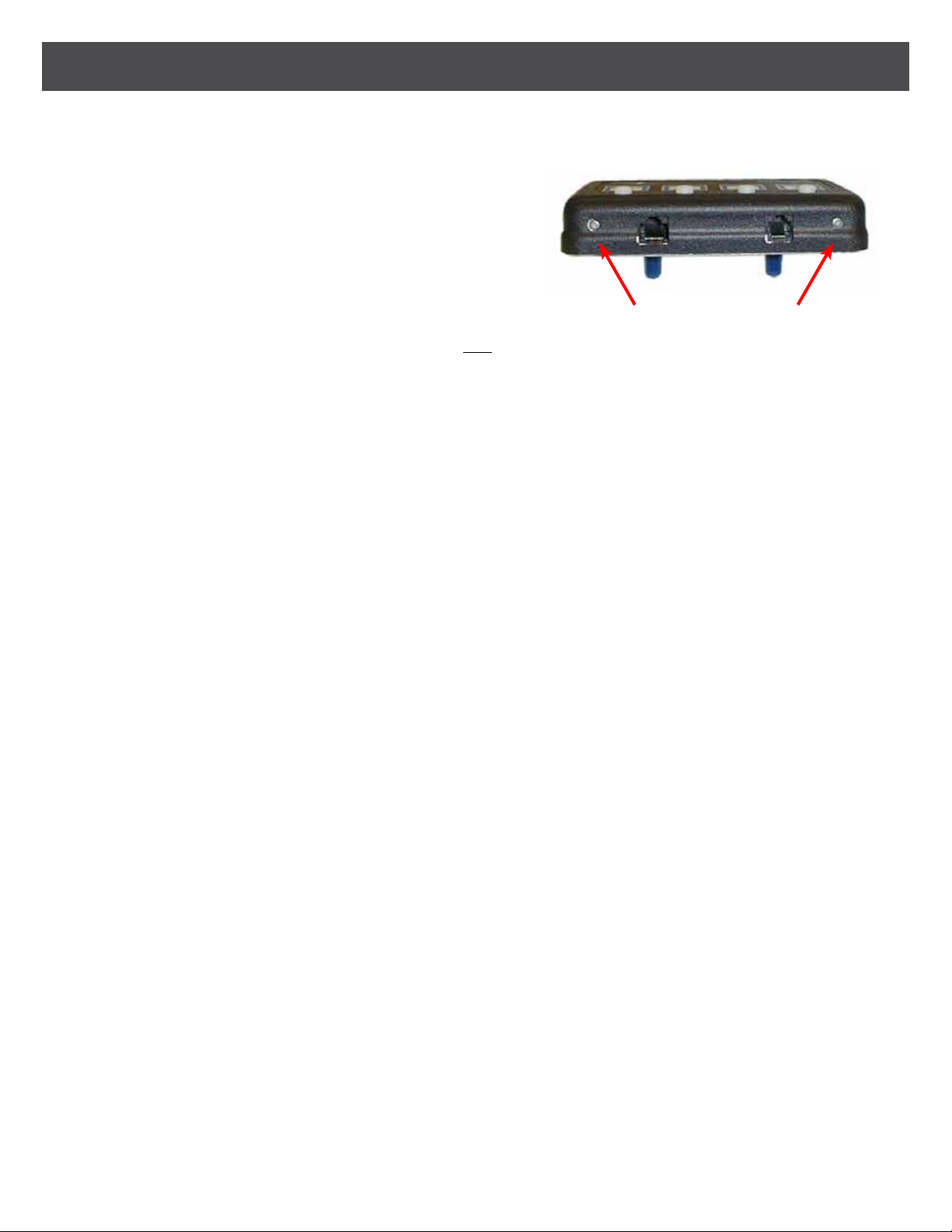
To calibrate the Smart Shift for your vehicle you will use the four gear selector keys and the two actuator control
buttons. The actuator control buttons are located on the front side of the controller on the left and right edges as
shown below. These two buttons are used to move the actuator in either direction when they are depressed, as
long as the ignition is “ON”and the brakes are applied. Once one of
the actuator control buttons is depressed, the actuator will move
in one direction and all four of the indicator lights on the touchpad
will illuminate to signify that you are in calibration mode. Use both
buttons to move the actuator to the desired position. Once the
actuator is positioned correctly, depress the corresponding button
on the touchpad.
IMPORTANT NOTE: If your vehicle is unable to reach all four of the Drive positions, program the un-used Drives for
the same setting as Drive. This way if the“D” key is pressed in error the actuator will still travel to the Drive position.
CALIBRATION PROCEDURE
Step 1: As discussed in the Actuator Installation section, in most installations the actuator will not meet the OEM
shift cable when the actuator is installed. For those cases you must rst adjust the actuator to meet the OEM
shift cable. Conrm that the Electronic Connections section has been completed, and the vehicle’s transmis-
sion is in Park. Turn on the ignition, start the vehicle, and apply and hold the brakes. (Remember the Smart-
Shift must receive a brake light input in order for the actuator to move.) Using the actuator control buttons,
position the actuator so that the OEM shift cable can attach to the actuator. Now, with the brake pedal de-
pressed, have someone attach the cable to the actuator according to the Installation section for your vehicle
type.
Step 2: With the engine still running and the brake depressed, use the Actuator Control Buttons to conrm that the
actuator can travel to the four main gears of the transmission (Park, Reverse, Neutral, & Drive). If not, some
adjustments to the placement of the OEM cable in relation to the bracket, or the OEM cable to the transmis-
sion will need to be made. If you are unable get the actuator to travel to these four positions, contact EMC
Service for assistance.
Step 3: After you have attached the cable and conrmed that the cable can travel to the required gear positions,
your ready to program the positions into memory. Remember, while in calibration mode all four LED’s will
illuminate. Using the Actuator Control Buttons, place the vehicle in Park and press the “P” key to set the
position. The Park LED should now be the only LED illuminated. Park has now be set. Each time the “P” key is
depressed, the actuator will track to Park.
Step 4: Using the Actuator Control Buttons, place the vehicle in Reverse and press the “R” key. Again the LED above
the Reverse icon will illuminate. Repeat this same step for Neutral and Drive.
Step 5: For Drive2 follow the same procedure to set the position, except you will need to press and hold the “D” key
to set Drive2. Once Drive2 is set the “D” LED indicator will ash continuously. Press the “D” key or any other
key to change out of Drive2 and to move to the selected position.
Step 6: Once all gear positions have been adjusted, you will need to check the operation from both directions, that
is, from Park to Drive (or Drive1) and Drive to Park. The reason for this is that each shift position has an area
or “window” in which it will operate or “drop into” a gear. When you set the positions from Park to Drive you
positioned it on the high side of this area or “window”. You must check to make sure that your high side ad-
justments are low enough to be activated from the low direction. If you are unable to“drop into” a gear from
the low side direction, use the actuator control buttons to reset the gears position slightly further to the low
side.
M11
3. CALIBRATION
13
Actuator Control Buttons

SMART-SHIFT INSTALLATION
14
When delivering the vehicle, be sure to go over the OEM operation of the transmission. Some vehicle’s utilizes
a lockout feature for Lower gears to prevent the transmission from entering if the vehicle is above a
certain speed. An example of this situation is if the operator of the vehicle is traveling at 30 mph and de-
cides that the grade is extremely long and steep or that the road conditions require a lower gear to save
on wear and tear of the vehicle, the operator only needs to depress the Drive key and the transmission
linkage will move to the low Drive position. The transmission, however, will only shift into low gear if the
vehicle slows down below the maximum speed allowable to access that gear. Therefore, no matter what
the driver selects below the Drive (D) position, the vehicle’s transmission will dictate when and if these
lower gears can be accessed.
CAUTION: THE EMC SMARTSHIFT ACTUATOR MUST BE EITHER PLACED IN NEUTRAL OR THE OEM
SHIFT CABLE DISCONNECTED FROM THE ACTUATOR BEFORE ATTEMPTING TO TOW THE VEHICLE.
Table of contents
Popular Automobile Accessories manuals by other brands


ULTIMATE SPEED
ULTIMATE SPEED 285690 Assembly and Safety Advice

Rockford Fosgate
Rockford Fosgate Polaris PMX-P2 Operation manual

InPOWER
InPOWER ITM131 owner's manual

Front Runner
Front Runner JADA010 quick start guide

WALMEC
WALMEC 40126 AL Mounting instructions

Audison
Audison FORZA AFBMW ReAMP 3 owner's manual


