Aewin SCB-6981 User manual

User’s Manual
AEWIN Technologies Co., Ltd Jan., 2013
1
Networking Appliance
Desktop Intel® Fanless Cedarview D2550/N2600 Network
System, 6 Copper GbE, CF, SATA, PCI-E, Bypass
User’s Manual
Version 1.0a

User’s Manual
AEWIN Technologies Co., Ltd Jan., 2013
2
© Copyright 2013. All Rights Reserved
Manual Edition 1.0a, Jul, 2013
This document contains proprietary information protected by copyright. All rights are reserved; no
part of this manual may be reproduced, copied, translated or transmitted in any form or by any means
without prior written permission of the manufacturer.
The content of this document is intended to be accurate and reliable; the original manufacturer assumes
no responsibility for any inaccuracies that may be contained in this manual. The original
manufacturer reserves the right to make improvements to the products described in this manual at any
time without prior notice.
Trademarks
IBM, EGA, VGA, XT/AT, OS/2 and PS/2 are registered trademarks of International business Machine
Corporation
Award is a trademark of Award Software International, Inc
Intel is a trademark of Intel
RTL is a trademark of Realtek
VIA is a trademark of VIA Technologies, Inc
Microsoft, Windows, Windows NT and MS-DOS are either trademarks or registered trademarks of
Microsoft Corporation
All other product names mentioned herein are used for identification purpose only and may be
trademarks and/or registered trademarks of their respective companies
Limitation of Liability
While reasonable efforts have been made to ensure the accuracy of this document, the manufacturer
and distributor assume no liability resulting from errors or omissions in this document, or from the use
of the information contained herein.
For more information on SCB-6981 or other AEWIN products, please visit our website
http://www.aewin.com.tw.
For technical supports or free catalog, please send your inquiry to

User’s Manual
AEWIN Technologies Co., Ltd Jan., 2013
3
Table of Contents
Chapter 1. General Information ..........................................................................4
1.1 Introducing.........................................................................................................4
1.3 Order Information..............................................................................................6
1.4 Packaging...........................................................................................................6
1.5 Precautions.........................................................................................................7
1.6 System Layout ...................................................................................................8
1.7 Board Dimension ...............................................................................................9
Chapter 2. Connector/Jumper Configuration..................................................10
2.1 Connector/Jumper Location and Definition.....................................................10
2.2 Connector and Jumper Setting.........................................................................12
2.3 CompactFlashTM Card Socket Pin Define........................................................22
Chapter 3. Utility & Driver Installation..............................................................23
3.1 Operation System Supporting..........................................................................23
3.2 System Driver Installation ...............................................................................24
3.3 LAN Driver Installation...................................................................................24
Appendix C: System Resources.............................................................................25
Appendix D: Cable Development Kit....................................................................28

User’s Manual
AEWIN Technologies Co., Ltd Jan., 2013
4
Chapter 1. General Information
1.1 Introducing
The SCB-6981 is a fanless networking platform designed for all business
environments and perfectly suited for small to medium offices. Built with
Intel® embedded IA components for warranted longevity; the SCB-6981 is
supported by Intel® Atom D2550, low-voltage processor with ICH10R I/O
controller.
In order to provide the best network performance and utilization, the platform
supports high bandwidth DDR3 SODIMM memory up to 4GB with a variety of
storage devices such as CompactFlash™and an optional 2.5”HDD.
The standard SCB-6981 provides six GbE ports with bypass function, two USB
2.0 ports, one RJ-45 console port and LED indicators that monitor power,
storage device activities for local system management, maintenance and
diagnostics. In addition, the SCB-6981 supports one mini0card socket and is
RohS, FCC and CE compliant.
To further enhance network security performance, the SCB-6981 has an
optional onboard Cavium Nitrox Lite CN505 providing hardware level
cryptographic acceleration and reallocating the abundant CPU computing
power for higher layer packet processing.

User’s Manual
AEWIN Technologies Co., Ltd Jan., 2013
5
1.2 Specification
Processor System
CPU
Intel® Cedarview-D D2550, N2600 Processors
Chipset
Intel® ICH10R
BIOS
AMIBIOS
Memory
Technology
Un-buffered and Non-ECC DDR3 800/1066MHz
memory
Capacity
Up to 4GB with one SO-DIMM socket
Expansion
Expansion Slots
One mini-card slot (Support USB bus only via
mini-PCIe slot) (Option)
Ethernet
GbE Ethernet
Six RJ45 GbE ports, Intel® 82583V, PCI-E x1 (one
pair bypass between LAN1 and LAN2)
LAN bypass
One ports bypass (Optional)
Storage
SATA HDD
One internal 2.5”SATA HDD bay
Compact Flash
Socket
One CompactFlashTM Type II
I/O
USB
Two external USB2.0
Serial
One RJ45 Console port (COM1)
One internal 5x2 pin header (COM2)
Power Supply
Watt
60W power supply, AC to DC 12V
Mechanical and
Environment
Form Factor
Desktop
LED
1 x Power LED (Green)
1 x HDD LED (Red)
1 x Bypass LED (Yellow)
6 pairs LEDs for 6 Ethernet ports Active/Link
status (Green)
Dimension(W x D
x H)
232mm (W) x 153mm (D) x 44mm (H)
(9.1W x 6”D x 1.7”H)
Operating
Temperature
Operating: 0 ~ 40°C ( 32 ~ 104°F )
Storage
Temperature
-20 ~ 75°C (-4 ~ 167°F)
Humidity
10 ~ 85% relative humidity, non-operating,
non-condensing
Weight
1pc/Box, 4kgs, 14cm(W) x 38cm(D) x 23.2cm(H)
5Boxes/CTN, 20kgs, 40cm(W) x 72.4cm(D) x 26.4cm(H)
Certification
CE/FCC

User’s Manual
AEWIN Technologies Co., Ltd Jan., 2013
6
1.3 Order Information
We offer some accessories for SCB-6981 appliance for customer need.
SCB-6981A-D18
Fanless Intel® ATOM D2550 Network System, DDR3, 6 RJ45 GbE,
SATA, CF, Bypass
SCB-6981B-D18
Fanless Intel® ATOM D2550 Network System, DDR3, 4 RJ45 GbE,
SATA, CF, PCI-E
DK001
Cable development kit
46L-CO5204-00 Cross over cable
46L-EC5200-00 Ethernet cable
46L-RJDB91-00 RJ45 Console cable
46L-DB9200-01 Null modem cable
46L-IVGA01-00 VGA cable
46L-IPS200-00 KB/MS cable
46L-IUSB01-00 USB cable
1.4 Packaging
Please make sure that the following items have been included in the package
before installation.
1. SCB-6981 Appliance
2. Quick Installation Guide (Optional)
3. Cables (Optional)
4. CD-ROM that contains the following folders:
(1) Manual
(2) System Driver
(3) Ethernet Driver
(4) Utility Tools
If any of the items above are missing or damaged, please contact your dealer
or retailer from whom you have purchased the SCB-6981. Keep the box and
carton for possible shipment or storage of the SCB-6981 in near future. After
unpacking the goods, please inspect and make sure the packaging is intact.
Do not plug the power adapter to the appliance of SCB-6981 if it is perceived
to be damaged.

User’s Manual
AEWIN Technologies Co., Ltd Jan., 2013
7
Note: Keep the SCB-6981 in the original packaging until you start installation.
1.5 Precautions
Please make sure you properly ground yourself before handling the SCB-6981
appliance or other system components. Electrostatic discharge can potentially
damage the SCB-6981 appliance.
Do not remove the anti-static packing until you are ready to install the
SCB-6981 appliance.
Ground yourself before removing any system component and protective
anti-static packaging. To ground yourself, grasp the expansion slot covers or
other unpainted parts of the computer chassis.
Handle the SCB-6981 appliance by its edges and avoid touching the
components on it.
User’s Manual
AEWIN Technologies Co., Ltd Jan., 2013
8
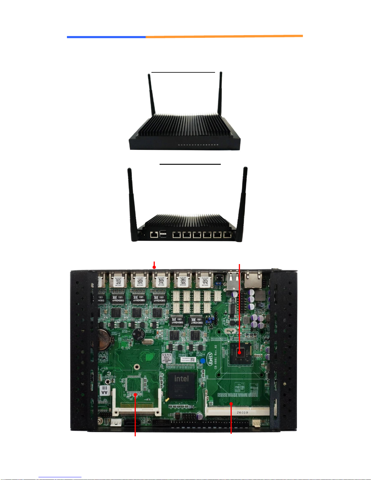
1.6 System Layout
SCB-6981 Front Side
Layout
SCB-6981 Rear Side
Layout
DDR3
SO-DIMM
CF card
2.5”SATA HDD Bay (underneath M/B)
CPU

User’s Manual
AEWIN Technologies Co., Ltd Jan., 2013
9
1.7 Board Dimension
User’s Manual
AEWIN Technologies Co., Ltd Jan., 2013
10
Chapter 2. Connector/Jumper Configuration
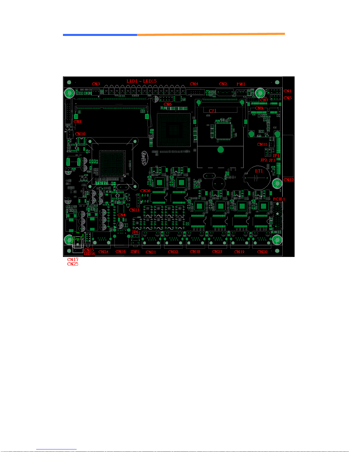
2.1 Connector/Jumper Location and Definition

User’s Manual
AEWIN Technologies Co., Ltd Jan., 2013
11
SCB-6981 Connector and Jumper:
Connector
Description
Connector
Description
CN1
KB/MS Connector
CN25
Power JACK +12V Connector
CN2
SATA Connector
CN26
Watchdog/Bypass selection
CN3
System FAN Connector
PCIE1
PCI-E x1 Slot
CN4
COM2 Connector
PW1
SATA Power Connector
CN5
SPI Connector
JP1
PCI-E slot +5V voltage selection
CN6
USB 2X5 Header (2.54mm)
JP2
PCI-E x1/x2 selection
CN7
Port 80 Connector
JP3
Clear CMOS
CN8
VGA Connector
JP6
GPI/Reset selection
CN9
Mini-PCIE Slot
LED1
Power LED
CN10
CPU FAN Connector
LED2
By Pass LED
CN11
WLAN LED Connector
LED3
HDD LED
CN12
PCI-E x4 Slot
LED4
LAN1 Active LED
CN13
Key Pad Connector
LED5
LAN1 Link LED
CN14
LCM Connector
LED6
LAN2 Active LED
CN15
LED Connector
LED7
LAN2 Link LED
CN16
USB Connector
LED8
LAN3 Active LED
CN17
2-Pin Power Connector
LED9
LAN3 Link LED
CN18
LAN3 Connector
LED10
LAN4 Active LED
CN19
LAN5 Connector
LED11
LAN4 Link LED
CN20
LAN6 Connector
LED12
LAN5 Active LED
CN21
LAN1 Connector
LED13
LAN5 Link LED
CN22
LAN2 Connector
LED14
LAN6 Active LED
CN23
LAN4 Connector
LED15
LAN6 Link LED
CN24
Console Port (RJ45)
LED16
Rear Side LED

User’s Manual
AEWIN Technologies Co., Ltd Jan., 2013
12
2.2 Connector and Jumper Setting
CN1: PS/2 KB/MS Pin Header
Pin
Define
Pin
Define
1
KCLK
2
MCLK
3
KDAT
4
MDAT
5
N/A
6
N/A
7
PS2_GND
8
PS2_GND
9
PS2_VCC
10
PS2_VCC
CN2: SATA Connector
Pin
Signal
1
Ground
2
TXP
3
TXN
4
Ground
5
RXN
6
RXP
7
Ground
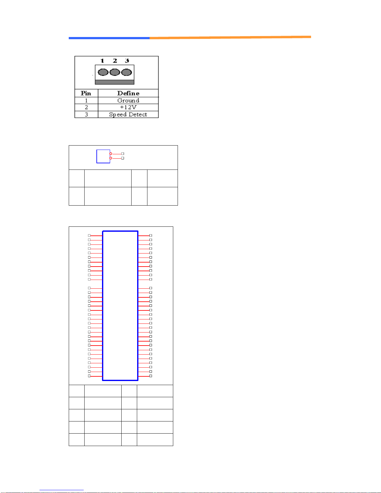
CN3: System FAN
Pin
Define
1
Ground
2
+12V
3
Speed Detect
CN4: COM2 pin header

User’s Manual
AEWIN Technologies Co., Ltd Jan., 2013
13
Pin
Define
Pin
Define
1
DCD#
6
DSR#
2
RXD#
7
RTS#
3
TXD#
8
CTS#
4
DTR#
9
RI#2
5
Ground
10
NC
CN5:SPI Pin Header
Pin
Define
Pin
Define
1
+3.3V
2
Ground
3
CS#
4
SCLK
5
MISO
6
MOSI
7
NONE
8
IO
CN6: USB Pin Header
Pin
Define
Pin
Define
1
+5V
2
+5V
3
USB1N
4
USB2N-
5
USB1P
6
USB2P
7
Ground
8
Ground
9
N/A
10
Ground
CN7: Port 80 Connector

User’s Manual
AEWIN Technologies Co., Ltd Jan., 2013
14
Pin
Define
Pin
Define
1
+3.3V
2
LAD0
3
LAD1
4
LAD2
5
LAD3
6
LFRAME_N
7
PLTRST_N
8
+5V
9
PORT80_PCLK
10
N/A
11
GND
12
GND
CN8: VGA pin header
Pin
Define
Pin
Define
1
RED
2
GREEN
3
BLUE
4
Reserved
5
GND
6
RED RTN
7
GREEN RTN
8
BLUE RTN
9
+5V
10
GND
11
Reserved
12
SDA
13
HSYNC
14
VSYNC
15
SCL
16
Reserved
CN10: CPU FAN CONNECTOR (not applicable)
User’s Manual
AEWIN Technologies Co., Ltd Jan., 2013
15
CN11: WLAN LED Connector
1
2
Pin
Define
Pin
Define
1
LED1_WLAN#
2
+3.3V
CN12: PCIE x4 Slot (Option, only support PCI-E x1/x2)
A1
A2
A3
A4
A5
A6
A7
A8
A9
A10
A11
A12
A13
A14
A15
A16
A17
A18
A19
A20
A21
A22
A23
A24
A25
A26
A27
A28
A29
A30
A31
A32
B1
B2
B3
B4
B5
B6
B7
B8
B9
B10
B11
B12
B13
B14
B15
B16
B17
B18
B19
B20
B21
B22
B23
B24
B25
B26
B27
B28
B29
B30
B31
B32
PRSNT1#
+12V
+12V
GND
TCK
TDI
TDO
TMS
+3.3V
+3.3V
RST#
GND
CLK+
CLK-
GND
RP0
RN0
GND
RSVD
GND
RP1
RN1
GND
GND
RP2
RN2
GND
GND
RP3
RN3
GND
RSVD
+12V
+12V
+12V
GND
SMCLK
SMDAT
GND
+3.3V
TRST#
3.3Vaux
WAKE#
RSVD
GND
TP0
TN0
GND
PRSNT2-1#
GND
TP1
TN1
GND
GND
TP2
TN2
GND
GND
TP3
TN3
GND
RSVD
PRSNT2-2#
GND
Pin
Define
Pin
Define
B1
+12V
A1
GND
B2
+12V
A2
+12V
B3
+12V
A3
+12V
B4
GND
A4
GND

User’s Manual
AEWIN Technologies Co., Ltd Jan., 2013
16
B5
SMBCLK
A5
+3.3V
B6
SMBDAT
A6
+3.3V
B7
GND
A7
TEST
B8
+3.3V
A8
+3.3V
B9
NC
A9
+3.3V
B10
+3.3V
A10
+3.3V
B11
NC
A11
PLTRST
B12
PWROK
A12
GND
B13
GND
A13
PCIECLKP
B14
TXP5
A14
PCIECLKN
B15
TXN5
A15
GND
B16
GND
A16
RXP5
B17
SLOT_+5V
A17
RXN5
B18
GND
A18
GND
B19
TXP6
A19
SLOT_+5V
B20
TXN6
A20
GND
B21
GND
A21
RXP6
B22
GND
A22
RXN6
B23
NC
A23
GND
B24
NC
A24
GND
B25
GND
A25
NC
B26
GND
A26
NC
B27
NC
A27
GND
B28
NC
A28
GND
B29
GND
A29
NC
B30
NC
A30
NC
B31
PCIESEL
A31
GND
B32
GND
A32
NC
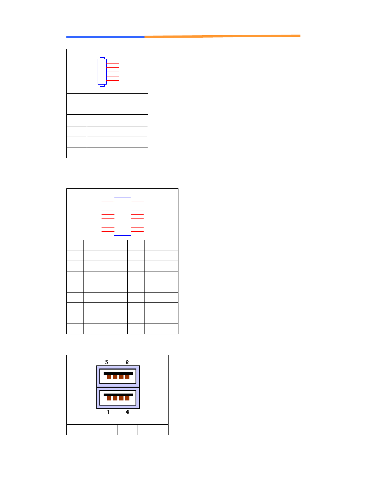
CN13: LCM KEYPAD Pin Header
User’s Manual
AEWIN Technologies Co., Ltd Jan., 2013
17
1
2
3
4
5
Pin
Define
1
ACK#
2
BUSY
3
PE
4
SLCT
5
Ground
CN14: LCM pin header
2
36
8
10
12
14
16
1
5
7
9
11
13
15
Pin
Define
Pin
Define
1
+5V
2
GND
3
P_AFD#
4
NC
5
P_INIT#
6
P_SLIN#
7
LCM_PD1
8
LCM_PD0
9
LCM_PD3
10
LCM_PD2
11
LCM_PD5
12
LCM_PD4
13
LCM_PD7
14
LCM_PD6
15
LCM_BK_CTRL
16
BK_CTRLP
CN16: USB Connector
Pin
Define
Pin
Define
User’s Manual
AEWIN Technologies Co., Ltd Jan., 2013
18
1
+5V
2
DATA0-
3
DATA0+
4
GND
5
+5V
6
DATA1-
7
DATA1+
8
GND
CN17: DC +12V Power Jack (2Pin) (Option, Only for SCB-7902)
11
22
Pin
Define
Pin
Define
1
+12V
2
GND
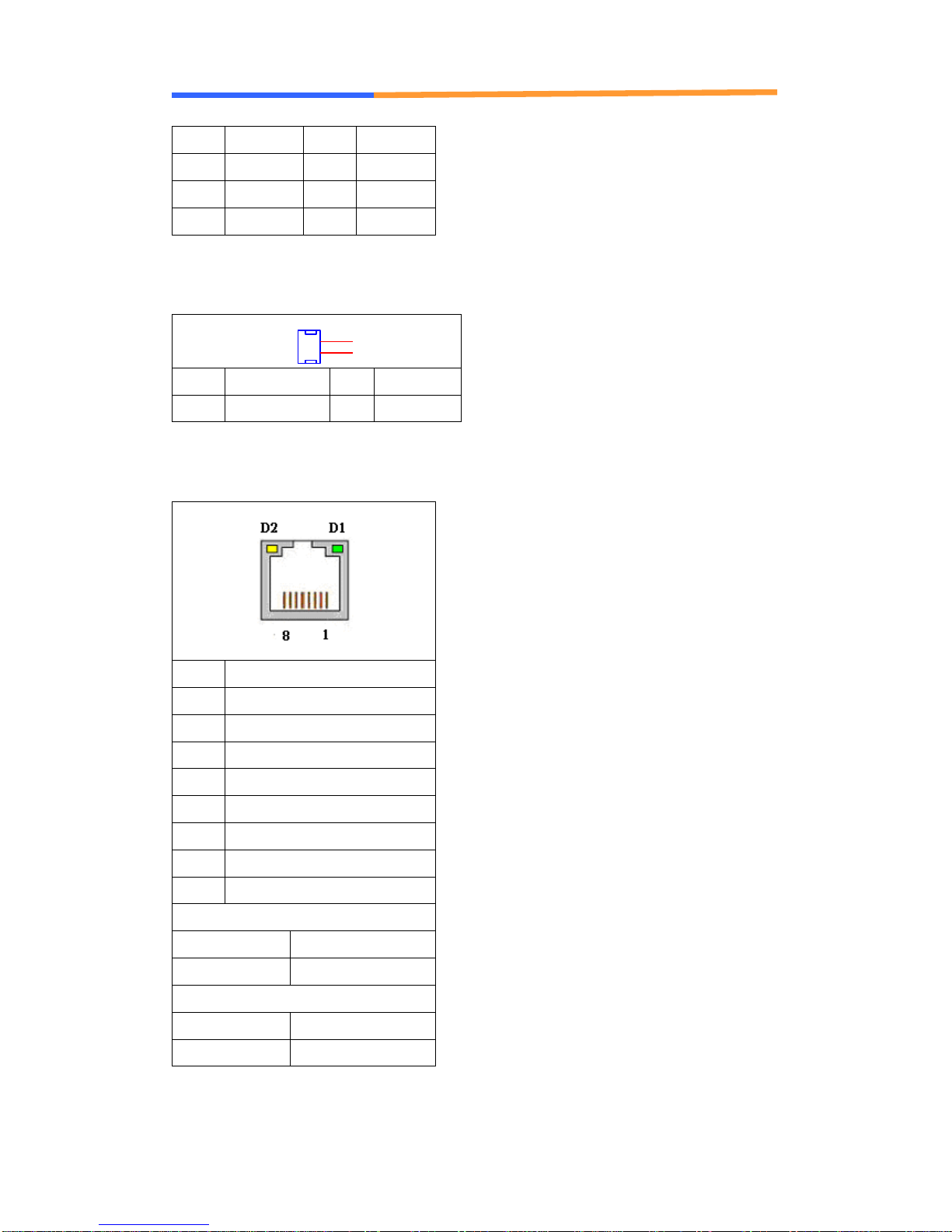
CN18/CN19/CN20/CN21/CN22/CN23: LAN RJ-45 Connector
Pin
Define
1
TX+
2
TX-
3
RX+
4
Chassis Ground
5
Chassis Ground
6
RX-
7
Chassis Ground
8
Chassis Ground
D1: Speed indicated LED
1 Gbps
GREEN
100 Mbps
YELLOW
D2 :Link/Activity LED
Link
GREEN
Activity
BLINKING
CN25: DC +12V Power Jack (2Pin)

User’s Manual
AEWIN Technologies Co., Ltd Jan., 2013
19
11
22
Pin
Define
Pin
Define
1
+12V
2
GND
CN26: Watchdog/Bypass selection
Pin
Status
Pin
Status
1-3
Watchdog mode(default)
2-4
By Pass Enable
3-5
By pass mode
4-6
By Pass Disable(default)
PCIE1: PCIEx1 SLOT
KEY
A1
A2
A3
A4
A5
A6
A7
A8
A9
A10
A11
A12
A13
A14
A15
A16
A17
A18B18
B17
B16
B15
B14
B13
B12
B11
B10
B9
B8
B7
B6
B5
B4
B3
B2
B1 PRSNT1*(B)
12V(P)
12V(P)
GND(P)
JTAG2(B)
JTAG3(B)
JTAG4(B)
JTAG5(B)
3.3V(P)
3.3V(P)
PWRGD(I)
GND(P)
REFCLK+(I)
REFCLK-(I)
GND(P)
HSIP0(O)
HSIN0(O)
GND(P)GND(P)
PRSNT2*(B)
GND(P)
HSON0(I)
HSOP0(I)
GND(P)
RSVD(B)
WAKE*(B)
3.3VAUX(I)
JTAG1(B)
3.3V(P)
GND(P)
SMDAT(B)
SMCLK(B)
GND(P)
12V(P)
12V(P)
12V(P)
Pin
Define
Pin
Define
B1
+12V
A1
GND
B2
+12V
A2
+12V
B3
+12V
A3
+12V
B4
GND
A4
GND

User’s Manual
AEWIN Technologies Co., Ltd Jan., 2013
20
B5
SMBCLK
A5
TCK
B6
SMBDAT
A6
TDI
B7
GND
A7
NC
B8
+3.3V
A8
TMS
B9
TRST#
A9
+3.3V
B10
+3.3V
A10
+3.3V
B11
NC
A11
PLTRST
B12
PWROK
A12
GND
B13
GND
A13
SLOTCLKP
B14
SLOTTXP
A14
SLOTCLKN
B15
SLOTTXN
A15
GND
B16
GND
A16
SLOTRXP
B17
NC
A17
SLOTRXN
B18
GND
A18
GND
PW1: HDD POWER
1
2
3
4
Pin
Define
1
+12V
2
GND
3
GND
4
+5V
Table of contents
Popular Network Router manuals by other brands

Federal Signal Corporation
Federal Signal Corporation AR2000-M Installation and maintenance manual

Pakedge Device & Software
Pakedge Device & Software RE-1 quick start guide

THOMSON
THOMSON TG608 Setup and user guide

Ruckus Wireless
Ruckus Wireless SmartZone 100 quick start guide

RCA
RCA DCW615A quick guide

Cisco
Cisco WRT350N Quick installation guide

Cisco
Cisco ASA 5585-X Maintenance manual

Patton electronics
Patton electronics 4110 Series quick start guide

SUMAVISION TECHNOLOGIES
SUMAVISION TECHNOLOGIES EMR3B operating instructions

NETGEAR
NETGEAR C6300 Quick start quide

Linksys
Linksys SPA2102-AN - Single Port Router Quick install guide

Amer
Amer SD7FX1SC installation guide


