AFA AFUR3322TE User manual

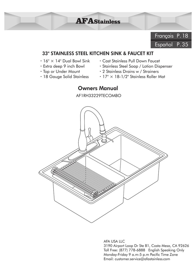
33" STAINLESS STEEL KITCHEN SINK & FAUCET KIT
AFA USA LLC
2450 Alton Parkway Irvine, CA 92606
Toll Free: (877) 778-6888
Monday-Saturday 8 a.m-6 p.m Pacific Time Zone
Email: customer.service@afastainless.com
AFUR3322TE/03CCOMB
·15.75" × 14" Dual Bowl Sink
·Extra deep 9 inch Bowl
·Top or Under Mount
·18 Gauge Solid Stainless
·Cast Stainless Pull Down Faucet
·Stainless Steel Soap / Lotion Dispenser
·2 Stainless Drains w / Strainers
·17" × 18-1/2" Stainless Roller Mat
Owners Manual
Français P.18
Español P.35

AFA STAINLESS PRODUCT SUPPORT TEAM
Customer service hotline
Toll Free: (877) 778-6888
Monday-Saturday 8 a.m-6 p.m Pacific Time Zone
Email: customer.service@afastainless.com
AFA USA LLC
2450 Alton Parkway
Irvine, CA 92606
SAFETY INFORMATION
Please read and understand this entire manual before attempting to
assemble, operate or install the product. Before beginning the assembly of
this product, compare the parts with the package contents and list. If any
part is missing or damaged do not attempt to assemble the product and
contact AFA Stainless customer service for assistance.
WARNING
• Follow the installation instructions carefully. Proper installation is the
installer’s responsibility.
CAUTION
• Check local building codes before beginning installation to ensure compliance.
• These instructions are based on application of composite material or solid surface countertop installation only.
Countertop applications of stone, granite, marble or butcher block should be referred to
an experienced countertop fabricator for custom installation.
• AFA stainless does not accept any liability for damage to countertop; sink fixture, faucet,
or personal injury during installation. Warranty may be void if it is determined installation
instructions were not followed.
This unit meets or exceeds the following:
• ASME A112.18.1
• CSA B125.1
• Listed by CUPC for use in the US and Canada
• Listed by California Energy Commission
California Title 20 Water-Efficiency Standards
Flow rate Kitchen faucet max. 1.8 GPM
AFUR3322TE/03CCOMB
Owners Manual
2

A-6 A-7
A-8
x2
x12
x12
E-1
E-2
F-1
F-2
F-3
F-4
F-5
PARTSLIST
x12
x12
x12
x12
x12
D-1
D-2
D-3
D-4
D-5
A-1
A-2
A-3
A-4
A-5
A-9
B-1
B-2
C-4
C-1 C-3
C-5
C-6
x 2
C-2
B-3
B-4
3
Faucet
A-1 Faucet Body
A-2 Deck Plate
A-3 Horseshoe Gasket
A-4 Hex M19 Nut
A-5 Hose Protector
A-6 Hot & Cold Supply Line
A-7 Weight With 2 screws
A-8 Installation Tool
A-9 Spray Hose
Sink
B-1 Sink
B-2 Soap/Lotion Hole Cover
B-3 Topmount Installation Template
B-4 Undermount Installation Template
Soap Dispenser
C-1 Spout & Pump
C-2 Tube
C-3 Bottle
C-4 Threaded Shank
C-5 Rubber Gasket
C-6 Lock Nut
Strainer
D-1 Strainer Basket Assembly
D-2 Strainer Bowl
D-3 Top Gasket
D-4 Bottom Gasket
D-5 Lock Nut
Top-mount Installation Clips
E-1 Screw 2"
E-2 Clip
Under-mount Installation Clips
F-1 Drop-In Anchor
F-2 Mounting Clip
F-3 Metal Washer
F-4 Wing Nut 1/4"-20
F-5 Screw

Rough-in Dimensions
4

Recommended Tools for Installation:
Electric Jig Saw Adjustable Wrench
T-5 T-6 T-7 T-8
Foam Adhesive
Pencil
T-1 (Included) T-2(Included) T-3 T-4
Important Information
·Before and during installation, please read and familiarize yourself with all installation
instructions for this product.
·Please keep all components, parts and accessories of this product away from small children
and minors. During installation, all screws, tools and small parts should be supervised so that
they do not fall into the hands of children.
·Use caution at all times when installing this product. Please ensure that you are physically able
to perform all parts of the installation and that you have the correct tools and equipment
needed. Before beginning, remove all wrappers and packing materials including staples and
packing straps.
·Please check to ensure that all components and parts are complete.
·For top-mount installations: For ease of installation we recommend installing the faucet and
soap dispenser to the sink prior to installation of the sink.
1/2" Drill Bit
Silicone Sealant
Electric Drill
T-9 T-10
Hammer
Flathead Screwdriver Phillips Screwdriver
1/4" Drill Bit
Channel Lock Wrench
T-11
Safety Glasses
T-12
Plumber Putty
T-13 T-14
5
Tape Measure Denatured AlcoholCloth
T-15 T-16
5/64" Allen Wrench

E
A-4
A-8
A-3
E
A-8
E
A-1
A-3
E
A-3
A-2
A-1
A-3
A-4
A-5
Remove Hose Protector (A-5), Hex
M19 Nut (A-4) and Horseshoe
Gasket (A-3) from bottom of faucet.
TOP MOUNT INSTALLATION
6
Soap/Lotion Hole Cover
23
Apply foam adhesive (T-1 ) Included
to the back of sink (B-1).
T-1
B-1
1
Tighten Hex M19 Nut (A-4) with
Installation Tool (A-8). Use
screwdriver through hole in
Installation Tool (A-8) to tighten
firmly.
Place Deck Plate (A-2) on to sink.
Place Faucet Body (A-1) into deck
plate and sink.
Slide Horseshoe Gasket (A-3) up on
to Faucet Body (A-1) under sink.
5
46
Remove soap/lotion hole cover (B-2)
from hole.

C-3
C-6
C-5 C-6
C-3
C-5
A-7
T-4
A
B
1
2
3
C
D
A-5
From under the sink, thread and
tighten the Bottle (C-3) onto
Threaded Shank (C-4)
Thread and tighten Hose Protector
(A-5) onto bottom of Faucet (A-1). Connect Faucet (A-1) Spray Hose
A to Quick Connect Adaptor B. Tighten weight (A-7) to spray hose
(A-9) with 2 screws provided. Measure
15 inches down from the underside
of the faucet on the spray hose. Pull
the faucet out of the spout to test
the distance and the retracting action.
Move the weight if necessary.
Be careful not to put weight so far
down on the hose that it rests on
the floor of the cabinet, or the spray
head won't retract all the way.
Secure Threaded Shank (C-4) by
sliding 1 Rubber Gasket (C-5)
onto bottom of Threaded Shank
(C-4) and tighten Tightening Nut
(C-6).
Slide 1 Rubber Gasket (C-5) onto
the bottom of the Threaded Shank
(C-4). Insert Threaded Shank
through Soap Dispenser sink hole.
10
89
12
7
11
7

T-7
T-11
D-2
D-2
D-3
D-3
D-4
D-4
D-5
D-5
D-1
D-2
D-3
D-4
D-5
T-5
B-3
Drill pilot holes (1/2" bit) on cut line.
Warning: Safety Glasses
recommended (T-12).
Place Top-mount Template (B-3) on
counter, cut along top-mount
installation line. Trace outside line
installation (as shown on template).
Prepare strainer for installation.
Loosen the Lock Nut, check to
ensure that all parts are complete.
Wipe any excess Plumber's Putty
away from top of the sink hole.
Place the Bottom Seal (D-4) on the
underside of the Strainer Bowl (D-2)
and tighten with Strainer Nut (D-5)
using Channel Lock Wrench (T-11).
Set the Strainer Bowl (D-2) and Top
Seal (D-3) into the hole from above
and push down firmly.
Apply a 1/4” bead of Plumber's
Putty (T-13) around the sink drain
hole as shown above.
Repeat for both sink holes.
18
16 17
15
14
13
8

T-10
3/8"
(6mm)
1/8"
(3mm)
T-16
T-15
x12
E-1
E-2
T-6
Center sink within counter opening.
Apply even pressure to all sides.
Apply a bead of silicon 1/8"-1/4"
away from edge of counter cutout
and then align sink on counter.
Carefully cut the counter hole using
a Jig Saw ). Carefully cut along (T-6
the inside of the drawn cut line.
Clean edge of counter top cutout
by Cloth (T-15) and Alcohol (T-16).
Prepare to install mounting clips
with screws (E-1/E-2). Slide Mounting Clips (E1 & E2) into
sink mounting rails. Center Clips
along each side of the sink, 2 Clips
on the 22” sides and 4 Clips on
the 33” sides as shown.
24
23
22
9
21
19 20

Hot
Cold
3/8" (9.5mm)
Hot
T-8
10
6
12
4
7 1
9
5
2 3
8
11
Clean excess silicon from edge of
of sink with rag.
Turn on hot and cold water by
turning handles counter clockwise,
turn on sink faucet and run for 5
minutes to make sure no leaks.
Attach hot and cold supply lines
(A-6) to shutoff valves. Tighten
with wrench clockwise until secure.
Connect the P-trap ( ) Not included
to the strainer.
Tighten mounting clips in numeral
order using flat head screwdriver
as shown above.
(Do not over tighten).
Tighten the screw (E-1).
Note: You might find it handy to
use flash light or hand held
worklight.
27
3029
28
26
25
10

C-1
C-2
C-1
C-2
Put roller mat on sink.
Connect Tube (C-2) to Spout and
Pump (C-1). Insert Spout and Pump
(C-1) and press the pump head
several times to prime system until
soap/lotion flows out of spout.
11
34
Fill soap or lotion into bottle.
Do not exceed 16 oz.
Turn on faucet and allow water to
flush lines for 15 seconds.
32 33
31

UNDER-MOUNT INSTALLATION
AFA stainless under-mount sinks can be installed with two different reveals- Positive and Zero– each creating a
distinctive look where the countertop and sink meet (see diagram). Deciding on your preferred look must be done
prior to installation.
Positive reveal – the countertop edge sits
approximately 1/8” back from the edge of the
sink, exposing the sink rim. All AFA stainless
undermount sinks feature a 3/4” finished rim.
All AFA stainless undermount sinks feature an
approximate 1/8” positive reveal.
Zero reveal – The countertop meets the edge of
the sink, fitting flush with the sink bowls.
12
CAUTION: These instructions are based on application of composite material or solid surface countertop
installation only. Countertop applications of stone, granite, marble or butcher block should be referred
to an experienced countertop fabricator for custom installation.
AFA Stainless does not accept any liability for damage to countertop; sink fixture, faucet, or personal
injury during installation. Warranty may be void if it is determined installation instructions were not
followed.
Recommended for professional installer only.
IMPORTANT: Provide your countertop manufacturer with the supplied sink and template for proper sink
hole cutting. A under-mount installation template is included with this product. And a PDF cut out hole
instruction can be sent by calling 877-778-6888 or Email: if you customer[email protected]
need.
Templates are supplied only as a guide. The physical use of the sink will ensure a more accurate cutout.

CLEANING AND CARE OF FILTER GASKET
23
1
Pull out the spray head.
Flush the filter gasket with water.
4
Put filter gasket back into spray
head.
56
Thread the spray head back onto the
spray hose in a clockwise direction.
Remove the filter gasket from spray.
13
Remove the spray head by turning
it in a counter clockwise direction.

T-2
5/64"
Hot
Cold
14
INSTALLATION OF CERAMIC CARTRIDGE
AFA Stainless is committed to producing the finest Solid Stainless Steel Faucet on the planet. A major component that
is a secret to AFA’s success, has been the long standing relationship with German manufactured Fluhs, the worlds
most advanced leader of high quality, technologically suburb ceramic cartridges guaranteed for life. In the rare case
of cartridge failure, AFA will replace the cartridge at no charge by calling our customer service hotline.
1-877-778-6888.
2
Ceramic cartridge is located
inside the diverter.
3
Using 5/64" (T-2 Included) Allen
Wrench carefully loosen set screw
inside diverter. (Do not remove
screw).
1
Turn off the water supply by
turning the water supply valve(s)
clockwise until it can no longer
be turned.
For safety and ease of faucet replacement, AFA
recommends these tools.
HELPFUL TOOLS
5/64" Allen Wrench
(T-2 included)
Flat Screwdrivers
(T-3)
Adjustable Wrench
(T-8)
Fluhs cartridge model # BFZU 1700

cartridge cover
7
Use Adjustable wrench and
unscrew retainer nut. Set aside.
8
Remove cartridge. Install new cartridge.
Reassemble faucet by reversing
steps.
9
9
Remove decorative collar and
set aside.
5
If Decorative Collar is tight
and not easy to remove, use
a flat head screwdriver and
carefully pry off the collar.
Set aside.
6
4
Remove diverter handle and set
aside.
15

Hot
Cold
10
Turn on Hot and Cold water
supply. Run water and check for
leaks.
16

17
– Please ensure that the surface of your AFA product has cooled down before cleaning (clean at room temperature).
– Use a soft cloth (e.g. a micro fibre cloth) to dry the product after every use.
– Do not use abrasive cleaning agents or tools – No scratching of the surface.
– Descaling is an aggressive process for products, so you should only do this when and where it is needed. Please wash the
product thoroughly with clean water after using any cleaning chemicals, then dry it with a soft cloth (e.g. a micro fiber
cloth).
– Do not use acidic or caustic cleaning agents or abrasive sponges.
– Do not use degreasing agents or too much cleaning agent.
– Do not spray directly onto the faucet.
– Do not use hard cleaning tools or materials.
– No scratching of the surface.
CLEANING AND CARE INSTRUCTIONS
LIFETIME LIMITED WARRANTY
AFA Stainless LLC warrants its products to be free of defects in material and workmanship during normal residential use for
as long as the original consumer purchaser owns his or her home. This warranty applies only to AFA Stainless products
installed in the USA. If a defect is found in normal residential use, AFA Stainless will, at its election, repair, replace or make
appropriate adjustment. Scratching, staining, acid or alkaline etching of the finish over time due to use, cleaning practices or
water or atmospheric conditions, are not manufacturing defects but are indicative of normal wear and tear, and are not
covered under this warranty. Damage caused by accident, misuse, or abuse, such as dents and scratches after installation, is
not covered by this warranty. Improper care and cleaning will void the warranty. Proof of purchase (original sales receipt)
must be provided to AFA Stainless with all warranty claims. AFA Stainless is not responsible for labor charges, installation, or
other incidental or consequential costs. In no event shall the liability of AFA Stainless exceed the purchase price of the
product. If AFA Stainless products are used commercially AFA Stainless warrants its products to be free from defects in
material and workmanship for five (5) years from the date of purchase, with all other terms of this warranty applying except
duration. If you believe that you have a warranty claim, please contact the AFA Stainless Customer Care Hotline at 877-778-
6888. or by writing to the address shown below.
AFA USA LLC
Attn: Customer Care
2450 Alton Parkway Irvine, CA 92606
Proof of purchase (original sales receipt) from the original consumer purchaser must accompany all warranty claims. Defects
or damage caused by the use of other than genuine AFA Stainless parts are not covered by this warranty. AFA STAINLESS
LLC AND/OR SELLER ARE PROVIDING THIS WARRANTY IN LIEU OF ALL OTHER WARRANTIES, EXPRESSED OR IMPLIED,
INCLUDING BUT NOT LIMITED TO THE IMPLIED WARRANTIES OF MERCHANTABILITY AND FITNESS FOR A PARTICULAR
PURPOSE. AFA STAINLESS LLC. AND/OR SELLER DISCLAIMS ANY LIABILITY FOR SPECIAL, INCIDENTAL, OR
CONSEQUENTIAL DAMAGES. Some states/provinces do not allow limitations on how long an implied warranty lasts or the
exclusion or limitation of such damages, so these limitations, and exclusions may not apply to you. This warranty gives the
consumer specific legal rights. You may also have other rights that vary from state/province to state/province. This warranty is
to the original consumer purchaser only, and excludes product damage due to installation error, product abuse, or product
misuse, whether performed by a contractor, Service Company or the consumer. This is AFA Stainless exclusive written
warranty. Manufacturers’ warranties may not apply in all cases, depending on factors such as use of the product, where the
product was purchased, or to whom you purchased the product from. Please review the warranty carefully, and contact the
AFA Stainless Customer Service Hotline if you have any questions.

ENSEMBLE ÉVIER 840 MM (33 PO) ET ROBINET DE
CUISINE EN ACIER INOXYDABLE
AFUR3322TE/03CCOMB
• Évier double
400mm (15,75 po)×355mm (14 po)
• Évier très profond 230mm (9 po)
• Installation en surface ou sous comptoir
• Acier inoxydable de calibre 18
• Robinet rétractable en acier inoxydable coulé
• Distributrice de savon ou lotion en acier inoxydable
• 2 drains en acier inoxydable avec crépines
• Tapis en acier inoxydable
432mm×470mmm (17×18-1/2 po)
Guide du propriétaire
AFA USA LLC
2450 Alton Parkway Irvine, CA 92606
Sans frais : 877-778-6888
Du lundi au samedi, de 8 h à 18 h HNE
Courriel : customer[email protected]
18

SÉCURITÉ – INFORMATION
Assurez-vous de lire et de comprendre entièrement ce guide avant
d'essayer d'assembler, d'utiliser ou d'installer ce produit. Avant de
commencer à assembler ce produit, comparer les pièces avec le contenu
de la boîte et la liste. Si des pièces sont manquantes ou endommagées,
n'essayez pas d'assembler le produit et communiquez avec le service à la clientèle
d'AFA Stainless pour obtenir de l'aide.
AVERTISSEMENT
• Suivre les instructions d'installation attentivement. L'installation adéquate
est la responsabilité de l'installateur.
ATTENTION
• Vérifier les règlements locaux en matière de construction avant de commencer l'installation, pour en
assurer la conformité.
• Ces instructions concernent uniquement l'installation sur un comptoir fait de matériaux composites ou
d'une matière homogène. Pour les comptoirs en pierre, granite, marbre ou bois, faire appel à un fabricant
de comptoirs expérimenté.
• AFA Stainless n'accepte aucune responsabilité pour les dommages causés au comptoir, à l'évier ou au robinet
et pour les blessures qui pourraient se produire pendant l'installation. La garantie peut être annulée s'il est
déterminé que les instructions d'installation n'ont pas été suivies correctement.
Cette unité respecte ou dépasse les normes suivantes :
• ASME A112.18.1
• CSA B125.1
• Désigné par le CUPC pour utilisation aux États-Unis et au Canada
• Désigné par la California Energy Commission
Normes de la Californie sur l'efficience de l'eau (Title 20)
Robinet de cuisine, débit d'eau maximal de 1,8 GPM
AFUR3322TE/03CCOMB
Guide du propriétaire
SERVICE À LA CLIENTÈLE AFA STAINLESS
Ligne sans frais : 877-778-6888
Du lundi au samedi de 8 h à 18 h HNP
Courriel : customer[email protected]
AFA USA LLC
2450 Alton Parkway Irvine, CA 92606
19

A-6 A-7
A-8
x2
x12
x12
E-1
E-2
F-1
F-2
F-3
F-4
F-5
PARTSLIST
x12
x12
x12
x12
x12
D-1
D-2
D-3
D-4
D-5
A-1
A-2
A-3
A-4
A-5
A-9
B-1
B-2
C-4
C-1 C-3
C-5
C-6
x 2
C-2
B-3
B-4
Robinet
A-1 Corps du robinet
A-2 Plaque
A-3 Joint en fer à cheval
A-4 Écrou hexagonal M19
A-5 Protecteur de tuyau
A-6 Conduite eau chaude / froide
A-7 Poids avec 2 vis
A-8 Outil d'installation
A-9 Tuyau pour douchette
Évier
B-1 Évier
B-2 Bouchon trou distributrice
B-3 Modèle installation en surface
B-4 Modèle installation sous comptoir
Distributrice de savon
C-1 Bec et pompe
C-2 Tube
C-3 Bouteille
C-4 Douille filetée
C-5 Joint en caoutchouc
C-6 Contre-écrou
Drain
D-1 Crépine
D-2 Réceptacle du drain
D-3 Joint supérieur
D-4 Joint inférieur
D-5 Contre-écrou
Agrafes pour installation en surface
E-1 Vis 50mm (2 po)
E-2 Agrafe
Agrafes pour installation sous comptoir
F-1 Pièce d'ancrage
F-2 Agrafe d'assemblage
F-3 Rondelle de métal
F-4 Écrou à oreilles 6 mm (1/4")-20
F-5 Vis
20
This manual suits for next models
1
Table of contents
Languages:
Other AFA Plumbing Product manuals
Popular Plumbing Product manuals by other brands

Honeywell
Honeywell V4770 Installation instruction

Glacier bay
Glacier bay 67573W-6001 Installation and care guide

baliv
baliv WT-130 manual

Delabie
Delabie Bioclip manual

Hans Grohe
Hans Grohe Vivenis 95 75033 1 Series Installation/User Instructions/Warranty

Signature Hardware
Signature Hardware GLENCROFT 484504 quick start guide

Spectrum Brands
Spectrum Brands Pfister Catalina LF-048-E0BY Quick installation guide

Kohler
Kohler K-6907 Homeowner's guide

Rohl
Rohl Miscelo MI12W2SDSTN instruction manual

Clou
Clou FreddoCL/06.03.002.29 installation instructions

Clou
Clou Flush 6 CL/03.08061 installation instructions

Dover
Dover FIBRELITE S2-160 manual