Afag PDZ-128 User manual

Gantry axis
PDZ-128 / PDZ-160 / PDZ-200
- Declaration of Incorporation
- Module Information
- Montage Instructions
- Maintenance Instructions
"Translation" of the Original Montage Instructions
© Copyright by Afag Automation AG

2 PDZ-128-160-200 OI-vers. 3.2 gb. 03.07.2018
These Montage Instructions apply to:
Gantry axis
PDZ-128
Gantry axis Gantry axis
PDZ-160 PDZ-200
Version of this documentation: PDZ Gantry axis
PDZ-128-160-200 OI-vers. 3.2 gb. 03.07.2018
Symbols: Assembly and initial start-up must be carried out by qualified personnel
only and according to these Montage Instructions.
.
DANGER
Indicates an immediate threatening danger.
Non-compliance with this information can result in death or
serious personal injuries (invalidity).
WARNING
Indicates a possible dangerous situation.
Non-compliance with this information can result in death or
serious personal injuries (invalidity).
CAUTION
Indicates a possibly dangerous situation.
Non-compliance with this information can result in damage to
property or light to medium personal injuries.
NOTE
Indicates general notes, useful operator tips and operating
recommendations which don't affect safety and health of the
personnel.
The actual serial number will
be sticked in here upon delivery of
the device.

PDZ-128-160-200 OI-vers. 3.2 gb. 03.07.2018 3
Table of contents
1.0.0 EC Declaration for Incorporation (Document original) ....................................... 5
1.1.0 According to: 2006/42/EC .............................................................................. 5
2.0.0 Module Information ............................................................................................ 6
2.1.0 Transport and storage (packing and unpacking) ............................................ 6
2.1.1 Overview for gantry module PDZ ................................................................... 7
2.1.2 Overview for motor and gear .......................................................................... 8
2.1.3 Regulation for the connection gantry axis. ..................................................... 9
2.1.4 Assembly possibility in annex slide .............................................................. 10
2.1.5 Centering bushings and assembly raster ..................................................... 10
2.1.6 Tightening torques for screw ........................................................................ 11
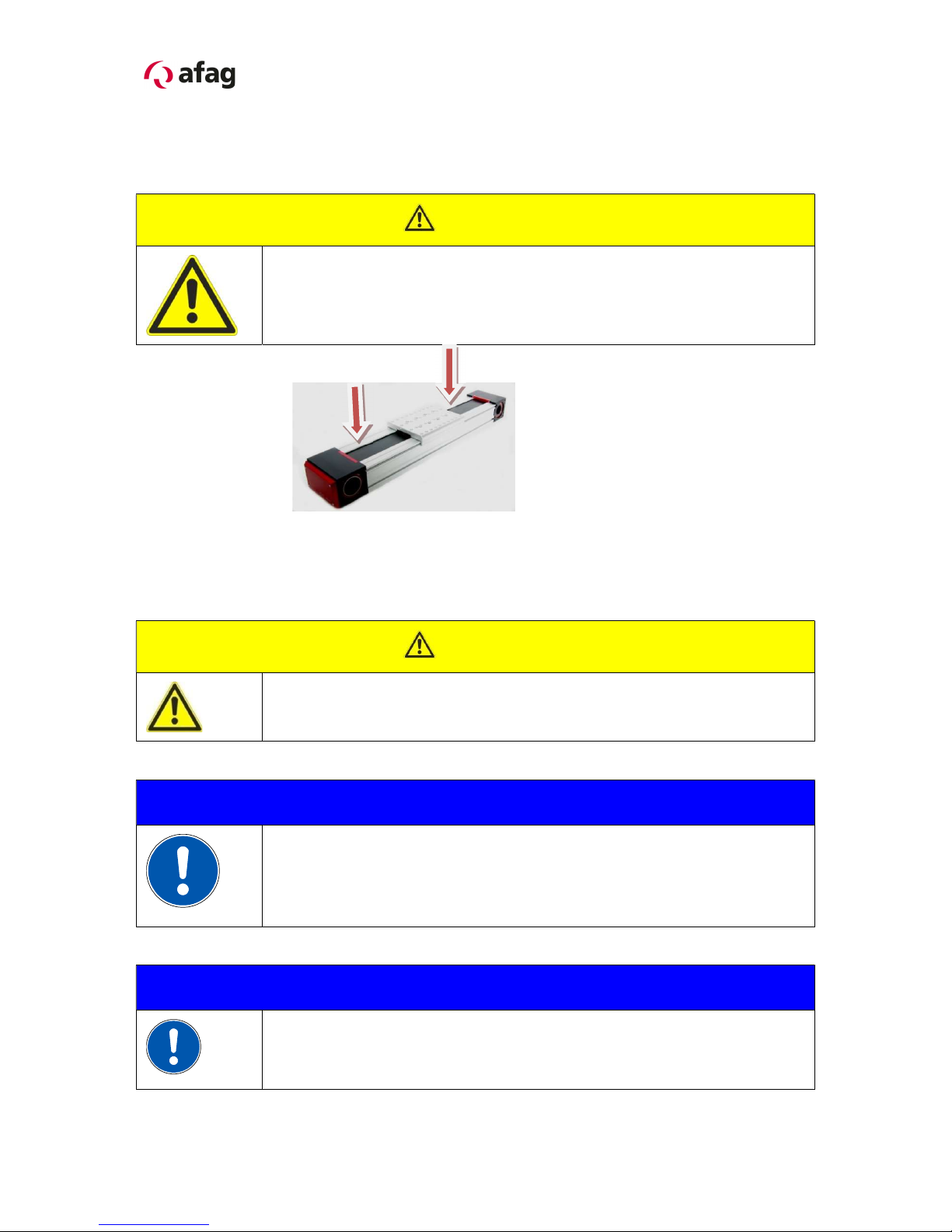
2.1.7 Safety tips .................................................................................................... 11
2.1.8 Redesign for the gear annex side ................................................................ 12
2.1.9 Go forward with gear redesign and motor .................................................... 13
2.2.0 Mounting third-party gears ........................................................................... 15
2.2.1 Preferred combinations to PDZ-128 ............................................................. 16
2.2.2 Preferred combinations to PDZ-160 ............................................................. 17
2.2.3 Preferred combinations to PDZ-200 ............................................................. 18
2.2.4 Installation of the gantry axis in a system ..................................................... 19
2.2.5 Tip for annex module ................................................................................... 19
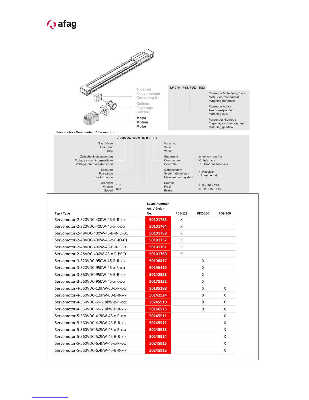
2.2.6 Motor connection.......................................................................................... 21
2.2.7 Electrical interfaces ...................................................................................... 21
2.2.8 Technical connection data servo motor ........................................................ 22
2.2.9 Programming of the gantry axis ................................................................... 23
2.3.1 Noise Emission ............................................................................................ 24
2.3.2 SE-Power control and technical data ........................................................... 25
3.0.0 Montage Instructions ....................................................................................... 26
3.1.0 Manufacturer address: ................................................................................. 26
3.1.1 General description ...................................................................................... 27
3.1.3 Included in the delivery ................................................................................ 28
3.1.4 Warranty ...................................................................................................... 29
3.1.5 Areas of application ...................................................................................... 29
3.1.6 Module description and construction ............................................................ 30
3.1.7 Module description ....................................................................................... 31
3.1.8 Dimensions PDZ-128 ................................................................................... 33
3.1.9 Technical data PDZ-128 .............................................................................. 34

4 PDZ-128-160-200 OI-vers. 3.2 gb. 03.07.2018
3.2.0 Slide unit load factors PDZ-128 ................................................................... 35
3.2.1 Dimensions PDZ-160 ................................................................................... 36
3.2.2 Technical data PDZ-160 .............................................................................. 37
3.2.3 Slid unit load factors PDZ-160 ..................................................................... 38
3.2.4 Dimensions PDZ-200 ................................................................................... 39
3.2.5 Technical data PDZ-200 .............................................................................. 40
3.2.6 Slide unit load factors PDZ-200 ................................................................... 41
3.2.7 Commissioning of the gantry axis ................................................................ 42
3.2.8 Programming ............................................................................................... 43
3.2.9 Hot surface on the motor .............................................................................. 43
4.0.0 Maintenance Instructions ................................................................................. 44
4.1.0 Maintenance and servicing of the PDZ gantry axis ...................................... 44
4.1.1 Further maintenance .................................................................................... 45
4.1.2 Lubrication of the linear guidance ................................................................ 45
4.1.3 Toothed belt spare part ................................................................................ 46
4.1.4 Replacement toothed belt: ........................................................................... 46
4.1.5 Toothed belt tension: .................................................................................... 48
4.1.6 Faults during operation ................................................................................ 49
4.1.7 Dismantling and repair for the gantry axis .................................................... 51
5.0.0 Accessories for the gantry axis ........................................................................ 52
6.0.0 Gantry axis superstructure ............................................................................... 53
6.1.0 Assembly process for Load transmission unit .............................................. 53
6.1.1 Accesories for synchronous drive ................................................................ 54
6.1.2 Gantry axis with double slide are special versions! ...................................... 54
6.1.3 Stroke limitation ........................................................................................... 55
6.1.4 Cover sensor nut (see technical catalog (Chapter 7) ................................ 55
7.0.0 Disposal ........................................................................................................... 56

PDZ-128-160-200 OI-vers. 3.2 gb. 03.07.2018 5
1.0.0 EC Declaration for Incorporation (Document original)
1.1.0 According to: 2006/42/EC
Standard: EN ISO 12100:2010 (German Version)
The manufacturer:
Afag Automation AG, Fiechtenstrasse 32, CH-4950 Huttwil
hereby declares that the incomplete machine:
Producte name: Gantry axis PDZ (electrical)
Types: PDZ-128 / PDZ-160 / PDZ-200
Relevant EC Machinery Directive:
EC Low Voltage Directive: 2014/35/EU
EMC Directive: 2014/30/EU
Norme machine: EN 60204-1:2006
Standard: EN ISO 12100:2010; EN 349
Safety of machinery General principles for risk assessment and risk reduction.
The special technical documents shall be sent to a reasoned request by national
authorities in printed documents or electronically (pdf).
Applied and fulfilled essential requirements:
1.1; 1.1.1; 1.1.2; 1.2; 1.2.1; 1.2.3; 1.2.4.4; 1.2.5; 1.3; 1.3.3; 1.3.5; 1.3.6; 1.3.7;
1.3.8.1; 1.3.8.2; 1.3.9; 1.4; 1.4.1; 1.5; 1.5.1; 1.6; 1.6.1; 1.6.3; 1.6.4; 1.7; 1.7.1;
1.7.4.; 1.7.4.1; 1.7.4.2; 1.7.4.3; 3.3.5; 3.4.1
Who installs this incomplete machine or assemble with other machines, a risk
assessment for its resulting machine which must make the provisions of the
EC directive: 2006/42 /EC
Norme: EN ISO 12100:2010
Agent:
For the compilation of the technically relevant documents:
Niklaus Röthlisberger, Productmanager Afag Automation AG, CH-4950 Huttwil
Place, Date: 03.07.2018
Siegfried Egli Niklaus Röthlisberger
Managing Director Productmanager HT
Afag Automation AG Afag Automation AG

6 PDZ-128-160-200 OI-vers. 3.2 gb. 03.07.2018
2.0.0 Module Information
2.1.0 Transport and storage (packing and unpacking)
CAUTION
Caution is required during packing and unpacking of the PDZ
gantry axis. In the case of careless handling of the gantry axis,
fingers can be crushed as the axis in the loose state can be
moved to and fro!
The module is transported in the transport packing of Afag Automation AG.
If packing of Afag Automation AG is not used, the axis must be packed in impact-
resistant and dust-proof packaging.
The axis should be stored dry in the transport packaging.
CAUTION
Caution is required to prevent back injuries during unpacking,
packing and carrying the PDZ gantry axes.
NOTE
Depending on the type of the gantry axis, the weight can be between
11.8 and 55 kg for the PDZ axes. We recommend binding the axes
with straps and using a hoist to lift them out of the packing crate. The
same also applies for the Installation of the gantry axes in an
assembly system.
NOTE
Please note! A technical safety information sheet is enclosed with
each module. This information sheet must be read by every person
who is involved with the module.

PDZ-128-160-200 OI-vers. 3.2 gb. 03.07.2018 7
2.1.1 Overview for gantry module PDZ
The Motor – and Gear annex is possible in the positions A / B / C / D.
Motor
PDZ
Angular gear
Planetary gear
Mounting flange
Slide

8 PDZ-128-160-200 OI-vers. 3.2 gb. 03.07.2018
2.1.2 Overview for motor and gear

PDZ-128-160-200 OI-vers. 3.2 gb. 03.07.2018 9
2.1.3 Regulation for the connection gantry axis.
The mounting surfaces for the gantry axes are at the bottom as standard; mounting
brackets can primarily be installed on the side grooves.
PDZ-128
PDZ-160 PDZ-200
Main mounting surface:
The main mounting surface of the axes is at the bottom in the 2 grooves!
In order to avoid tensions, ensure that the bolting surface shows an evenness of at
least 0.15 mm.
NOTE
Lateral groove may be used to attach the axles only in connection
with the connection set (clamps)!
see the accessories under Pt. 4.1.8 or in the catalog!
Main mounting surfaces

10 PDZ-128-160-200 OI-vers. 3.2 gb. 03.07.2018
2.1.4 Assembly possibility in annex slide
PDZ-128
PDZ-160 PDZ-200
2.1.5 Centering bushings and assembly raster
PDZ
PDZ
-
128
PDZ
-
160
PDZ
-
200
Hole raster 30x30 24x48 30x60
Attachment threads
M4
M6
M8
Centering bushings (H7)
Ø
7
mm
Ø9 mm
Ø12 mm
Use the centering bushings included in the scope of supply for positioning and
insert these sleeves in the diagonally opposite bore holes of the mounting grid.

PDZ-128-160-200 OI-vers. 3.2 gb. 03.07.2018 11
2.1.6 Tightening torques for screw
The bolts to be used for assembly must satisfy at least the following conditions:
Standard: VDI 2230
Strength: class 8.8
Surface: galvanised blue, oiled or greased
Thread Tightening torques
M3 1.1 … 1.4 Nm
M4 2.6 … 3.3 Nm
M5 5.2 … 6.5 Nm
M6 9.0 ... 11.3 Nm
M8 21.6 … 27.3 Nm
This is an incomplete machine
Assembly of the PDZ gantry axis in a system
The series of the PDZ gantry axis is used for the linear, smooth movement of rigidly
mounted loads under the ambient and Installation conditions defined for this module,
see Technical data. The PDZ gantry axis can be Installed in the horizontal or vertical
position.
2.1.7 Safety tips
NOTE
These Montage Instructions should be read carefully before carrying
out any activity on or with the PDZ gantry axis. The PDZ gantry axis
may only be deployed in accordance with the intended use.
NOTE
Safety instructions
Modifications on the PDZ gantry axis that are not described in these
Montage Instructions or have not been approved in writing by Afag
Automation AG are not permitted. In case of improper changes or
assembly, installation, operation and maintenance or repairs Afag
rejects all liability.

12 PDZ-128-160-200 OI-vers. 3.2 gb. 03.07.2018
2.1.8 Redesign for the gear annex side
If necessary, the gear or motor can be attached with relatively little effort to the
positions A/B/C/D.
NOTE
The rotation direction of the motor must be adjusted accordingly
depending on the selection of the attachment side.
NOTE
A stable substructure is required for the installation of the PDZ gantry
axes in a system; all bolts must be tightened according to the
specified tightening torques.

PDZ-128-160-200 OI-vers. 3.2 gb. 03.07.2018 13
2.1.9 Go forward with gear redesign and motor
CAUTION
Changing the gear attachment side must only be performed when the
gantry axis is removed. The gantry axis must be disconnected from
the mains power supply for this purpose.
The rotation direction of the motor must be reversed
(changed) afterwards!
Carry out a reference run with the axis afterwards!
(see Controller manual)
1. Check that the gantry axis is disconnected from the power supply.
2. Detach the connection cables from the gantry axis.
3. Remove the motor and encoder plug.
4. Remove adapter, gear and motor as a package:
4.1. Undo 4 bolts (1) on the clamping set.
4.2. Screw the 2 bolts into the extractor thread until the clamping set
detaches.
4.3. Screw the bolts back into the clamping thread
5. Remove the four bolts (2).
6. Remove gear adapter (3) together with gear and motor.
7. Push spacer (4) and then the clamping set onto the gear shaft as far as the stop.
8. Push gear shaft with the clamping set on the opposite side into the hollow shaft.
9. Secure gear adapter with the 4 bolts – do not tighten the bolts yet! Only tighten
the bolts so far that the adapter is completely on the mounting surface.
PDZ-128 4 x M4 PDZ-160 4 x M6 PDZ-200 4x M8
10. Tighten clamping set:
11. Clamping screws in the order of 1-6 bi as, then tighten in the same order evenly
to the specified torque with a torque wrench in brass.Tighten gear adapter with
the four bolts.
12. Connect the motor and encoder plug.
13. The voltages and currents applied can cause personal injuries and damage to
property (reference the axis again).

14 PDZ-128-160-200 OI-vers. 3.2 gb. 03.07.2018
Gantry axis
Motor
3
Gear
Mounting flange
Tightening torques for screw (Class 12.9)
M4 5.6 Nm
M5 11.2 Nm
M6 19.3 Nm
M8 46.9 Nm
Bolt (2) for the
adapter mounting
and the axis
Adapter (3)
Bolt for the gear
mounting
(4) Distance shell
Instep sentence
1
2
3
Order at 1-6
tighten
.

PDZ-128-160-200 OI-vers. 3.2 gb. 03.07.2018 15
2.2.0 Mounting third-party gears
Gear from other suppliers than Afag can also be attached to the axis. The procedure
for changing the gearbox and mounting the motor must always be the same as
described in section 2.1.9.
The following conditions must be met:
The diameter of the gear output shaft must be 16/22/32 mm PDZ. These
dimensions are derived from the size of the appropriate attachment set.
An adapter matching the mounting surface (see drawing below) incl. centering
collar must be constructed. The mounting surfaces are identical on the left-
hand and right-hand side.
Typen
A
B
C
D
E
F
G
H
J
K
PDZ
-
128
38
56
61
M5
32
82
PDZ
-
160
69 76 M6 40 80 4 98
PDZ
-
200
62
92 100 98 M8 M8 55 100 4 123
The circlip (blue) must be removed BEFORE mounting the gear unit!
If the gear unit is relocated, the corresponding circlip must also be relocated!
NOTE
Only use third party gears which are suitable for the Installation of
the gantry axis and comply with the requirements!
Circlip Circlip

16 PDZ-128-160-200 OI-vers. 3.2 gb. 03.07.2018
2.2.1 Preferred combinations to PDZ-128

PDZ-128-160-200 OI-vers. 3.2 gb. 03.07.2018 17
2.2.2 Preferred combinations to PDZ-160

18 PDZ-128-160-200 OI-vers. 3.2 gb. 03.07.2018
2.2.3 Preferred combinations to PDZ-200

PDZ-128-160-200 OI-vers. 3.2 gb. 03.07.2018 19
2.2.4 Installation of the gantry axis in a system
CAUTION
Caution is required during the installation of the gantry axis so
that fingers do not get crushed!
Heavy gantry axes must be installed using lifting gear.
CAUTION
The Installation of the gantry axis in a system must only be
performed when the controller is switched off and secured
against restarting. The Installation of the gantry axis must only
be performed by a qualified skilled person.
Only disconnect or connect cables when the control system is
switched off.
2.2.5 Tip for annex module
NOTE
All attachment modules must withstand the occurring forces
(accelerations). Gripper fingers are attached by the customer; these
must be designed accordingly for the application case so that the
gripping workpieces do not fly away during operation and endanger
persons.

20 PDZ-128-160-200 OI-vers. 3.2 gb. 03.07.2018
CAUTION
The system must have a safety fence for the Installation of the
gantry axis so that persons are not endangered during
operation.
Annexe module
Other manuals for PDZ-128
1
This manual suits for next models
2
Table of contents
Other Afag Industrial Electrical manuals
Popular Industrial Electrical manuals by other brands

Murata
Murata GRT21BR60J335KE13 Series Reference sheet

Murata
Murata GRM1885C1H8R2DA01 Series Reference sheet

Murata
Murata GRM31CR61H106KA12 Series Reference sheet

Murata
Murata GRM219R61C475KE15 Series Reference sheet

Murata
Murata GRM0335C1H510GA01 Series Reference sheet

Murata
Murata GRM155R71A474KE01 Series Reference sheet

Murata
Murata GRM0335C1E1R5BA01 Series Reference sheet

Murata
Murata GRM0225C1E9R6CDAE Series Reference sheet

Murata
Murata GQM1885C1H100GB01 Series Reference sheet

Eaton
Eaton XTCE580N Series Instruction leaflet

Murata
Murata GQM1885C1H101JB01 Series Reference sheet

Murata
Murata GRM3195C2A103JA01 Series Reference sheet