aFe Power 77-46101 SCORCHER HD User manual

advanced FLOW engineering
Instruction Manual P/N: 77-44006
Make: GM Model: Silverado HD/Sierra HD Year: 2004.5-2010 Engine: V8-6.6L (td)
Performance Chips

Label Qty. Description Part Number
A 1 Module R77-44006
B 1 LED Switch 05-70001
C 2 Velcro (2 Inches) 05-01244
D 4 Cable Ties 05-60167
E 1 Shim, Kit 03-50504
• Please read the entire instruction manual before proceeding.
• Ensure all components listed are present.
• Ensure you have all necessary tools before proceeding.
• Do not attempt to work on your vehicle when the engine is hot.
• Disconnect the negative battery terminal before proceeding.
• Retain factory parts for future use.
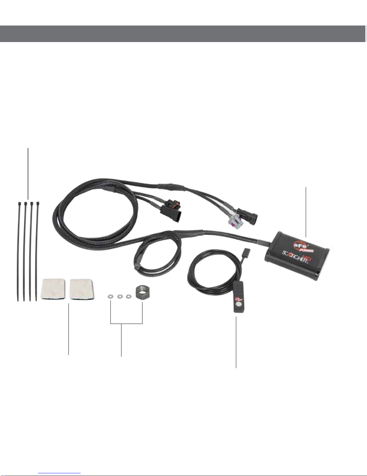
A
D
C
B
E

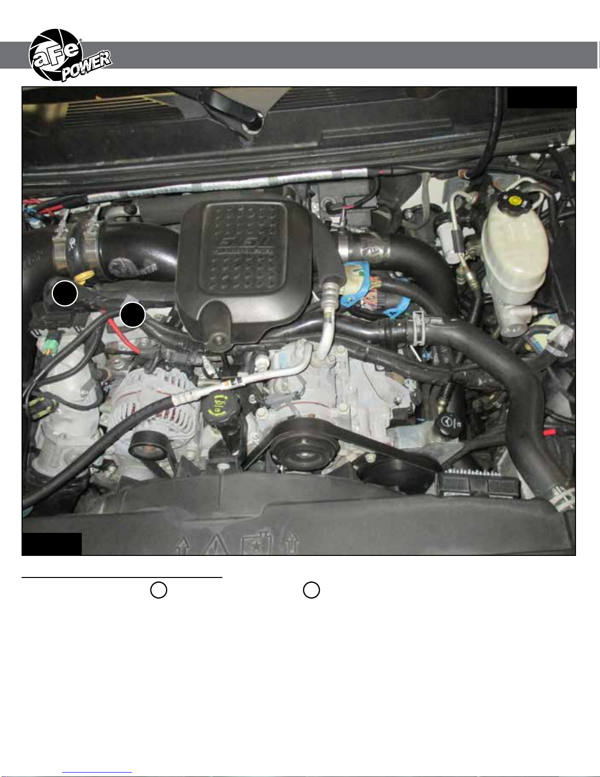
Refer to Figure A for Step 1.
Step 1: Locate the MAP 1 and Fuel Pressure sensor 2 . The Fuel Pressure sensor is located on the
passenger side of the engine under the intake tube close to the firewall. The MAP sensor is
located on the intake manifold under the EGR.
REMOVAL
1
2
Figure A

Refer to Figure B for Steps 2-4.
Step 2: Locate the glow plug controller by the driver side, behind the boost tube.
Step 3: Disconnect the harness and plug connecting to the controller.
Step 4: Remove the two 10mm bolts retaining the controller and remove out of vehicle.
REMOVAL
Figure B

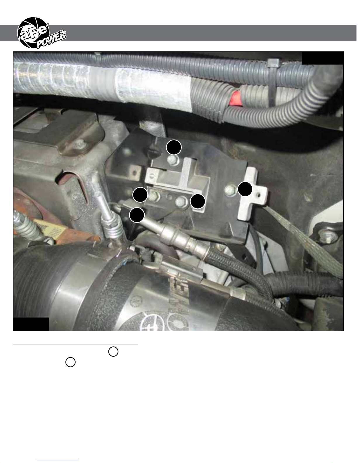
Refer to Figures C for Step 5.
Step 5: Remove the four bolts 3 on the glow plug controller bracket along with the bracket holding the
fuel line 4 and remove out of vehicle.
Figure C
REMOVAL
3
3
3
3
4

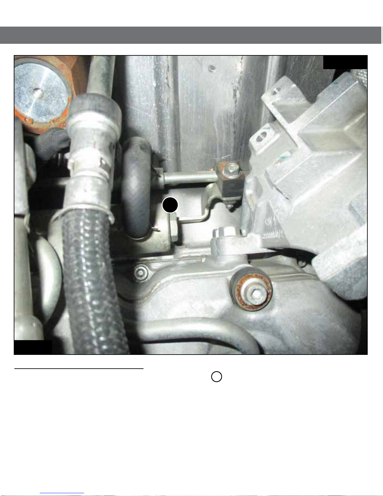
Refer to Figure D for Step 6.
Step 6: With an 18mm wrench remove the fuel relief valve 5 .
Figure D
REMOVAL
5

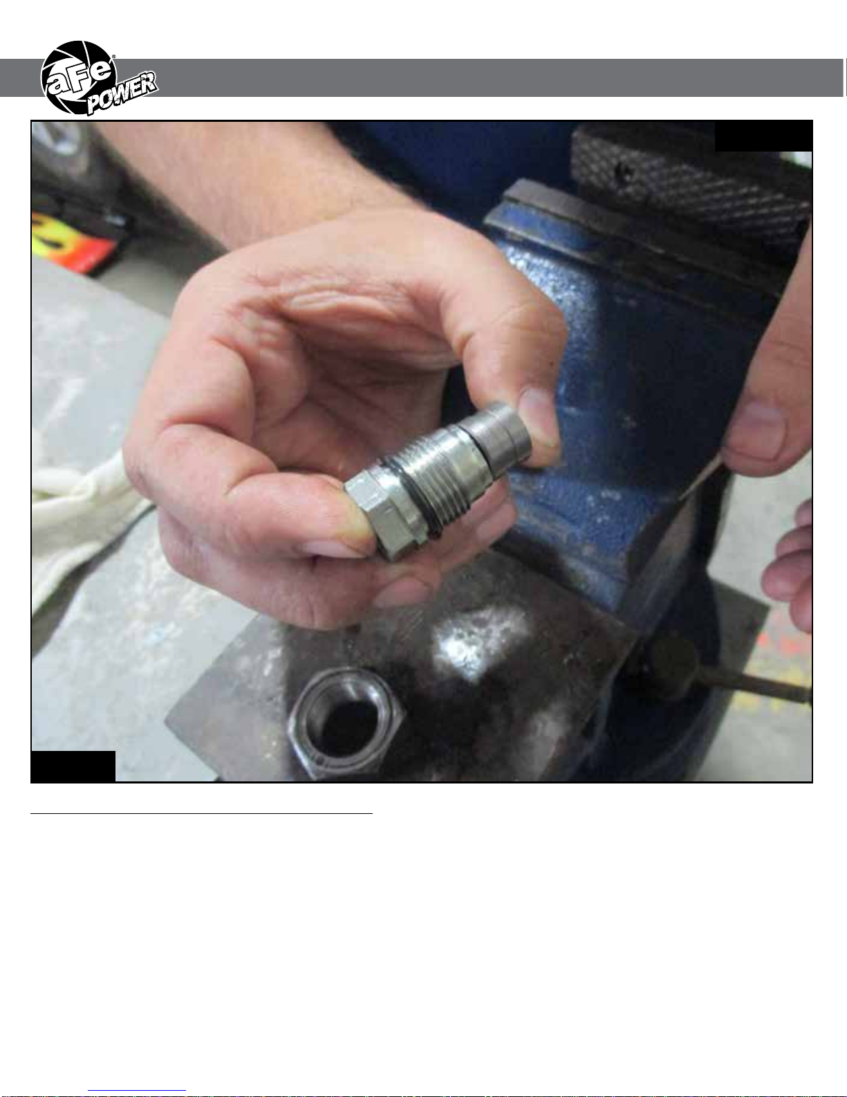
Refer to Figure E for Steps 7-9.
Step 7: Thread the removal tool onto the fuel relief valve.
Step 8: Place the tip of the fuel relive valve on the edge of a vise and tighten.
Step 9: Turn the removal tool clockwise towards the vise to split the fuel relief valve.
Note: Be cautious and hold the end of the fuel relive valve it is spring loaded and not mixing the
components alignment is very important. Locate behind the 3 hole washer is a very small
pin that should not be moved or lost, losing it will cause the vehicle to not start.
Figure E
INSTALL

Page left blank intentionally
Refer to Figure F for Step 10.
Step 10: Remove the small spring 6 and place the 3 shims in the fuel relief valve and re-insert the
spring.
Figure F
INSTALL
6

Refer to Figure G for Steps 11-15.
Step 11: Assuring no components were lost or misaligned reinsert the tip into the fuel relief valve.
Step 12: Place the fuel relief valve into the vise and compress back together.
Step 13: With a small punch re-punch the 3 small indentations securing the tip of the fuel relive valve to
the body.
Step 14: Place the fuel relief valve back into the fuel rail and tighten to 75 ft-lbs of torque, or fuel can leak
out.
Step 15: Refer to steps 6-10 to re-install all the components removed to access the fuel relief valve.
Note: Using a piece of wood between the tip and the vice will insure the tip does not get damaged.
Figure G
INSTALL

Page left blank intentionally
Refer to Figure H for Step 16.
Step 16: Remove the intake air tube out of vehicle to gain access to the fuel rail.
Figure H
INSTALL

Refer to Figure I for Steps 17-18.
Step 17: Locate and disconnect the fuel pressure sensor.
Step 18: Locate the fuel pressure sensor jumper harness on the aFe module. This is the shorter harness
with a black/orange connectors. Plug the male connector of the module to the stock fuel
pressure sensor, then take the female connector of the module and connect to the male
connector of the engine harness.
Note: Make sure connections are fully engaged. Usually, connectors make a snapping sound
when fully engaged.
Figure I
INSTALL

Page left blank intentionally
Refer to Figure J for Steps 19-20.
Step 19: Disconnect the MAP sensor.
Step 20: Locate the MAP sensor jumper harness on the aFe module. This is the longer harness with a
grey/orange connector. Plug the female connector of the module to the male connector of the
engine harness, then the male connector of the module to the stock map sensor of the
engine.
Figure J
INSTALL

Refer to Figure K for Steps 21-22.
Step 21: Carefully rout the switch behind steering wheel cover.
Step 22: Mount the Switch on an open, flat surface.
Figure K
INSTALL

Page left blank intentionally
Refer to Figure L for Step 23.
Step 23: Route the switch cable through firewall and into the engine bay. Follow the main harness
through the grommet into the firewall. Plug the end of the cable to the module.
Figure L
INSTALL

Refer to Figure M for Steps 24.
Step 24: Mount the module in a safe location, using the supplied Velcro strip. Then, secure the wires and
module away from any extreme heat and moving parts, with the provided ties. Make sure all
connections are secured and fully engaged.
Figure M
INSTALL

Refer to Figure G for Step 10.
Step 10: When turning on the vehicle, the switch will go through the light. It will stop at its last setting.
The LED on the switch represents the different level of power.
• Green LED: Stock
• Yellow LED: Sport
• Orange LED: Sport+
• Red LED: Race
Use the grey button to select the desired setting. Power adjustments can be done at any
moment.
Thank you for choosing aFe POWER!
Figure G
INSTALL

P/N: 46-20048 (Cold Side)
46-20049 (Hot Side)
Intercooler Tubes Rear Differential Cover
P/N: 46-70012-WL (w/ Oil)
46-700012 (Blk)
46-70010 (RAW)
P/N: 46-70072 (Blk)
46-70070 (RAW)
Transmission Pan Cover Air Intake System
P/N: 50-74002 (P10R)
51-74002 (PDS)
P/N: 50-74004 (P10R)
51-74004 (PDS)
Air Intake System Sprint Booster
P/N: 77-14003 (‘07-15’) P/N: 49-44060-P (Pol)
49-44060-B (Blk)
Exhaust System Transmission Filter
P/N: 44-TF006 (Deep Pan)
44-TF009 (Shallow Pan)
P/N: 44-LF001
Oil Filter
P/N: 49-44055
Exhaust Race Pipe Diesel Fuel System
P/N: 42-14011 (Full-time)
42-14012 (Part-time)
Oil Cap
P/N: 79-12002

Warranty
General Terms:
• aFe warrants their products to be free from manufacturer’s defects due to workmanship and material.
• This warranty applies only to the original purchaser of the product and is non-transferrable.
• Proof of purchase of the aFe product is required for all warranty claims.
• Warranty is valid provided aFe instructions for installation and/or cleaning were properly followed.
• Proper maintenance with regular inspections of product is required to insure warranty coverage.
• Damage due to improper installation, abuse, unauthorized repair or alteration is not warranted.
• Incidental or consequential damages or cost, including installation and removal of part, incurred due to failure of aFe
product is not covered under this warranty.
Product Category P/N Prefix Warranty duration
Direct OE Replacement Filters 10, 11, 30, 31, 71, 73 Life of the vehicle
Racing Filters 18 1 year
Universal 21, 24, 72,TF 2 years
Air Intake Systems 50, 51, 54, 55, 75,TR.TA,TL 2 years
Exhaust Systems 49 2 years
Intercoolers & Intercooler Tubes 46-2 2 years
Intake Manifolds 46-1 2 years
Differential Cover 46-7 Life of the vehicle
Exhaust Manifolds 46 2 years
Throttle Body Spacers 46-3 2 years
Fluid Filters 44 90 days
Pre-Filters 28 2 years
Heavy Duty OE Replacement 70 2 years
PowerSports OE Replacement 81, 87 2 years
PowerSports Intake Systems 85 2 years
Tuners 77 Contact aFe
No other warranty expressed or implied applies nor is any person or advanced FLOW engineering authorized to assume any other
warranty. Some States do not allow the exclusion or limitation of incidental or consequential damages or do not allow limitations on
how long an implied warranty lasts, so the above limitations or exclusions may not apply to you. This warranty gives you specific
legal rights, and you may also have other rights which vary from State to State.
Table of contents
Other aFe Power Control Unit manuals
Popular Control Unit manuals by other brands

Xycom
Xycom XVME-682 manual

Velleman
Velleman Velbus VMB4PD manual

Midcontinent
Midcontinent MD41-1510 Installation manual and operating instructions

Runxin
Runxin 53520 instruction manual

PS Engineering
PS Engineering 11645R Installation and operation manual

Siemens
Siemens SIMATIC ET 200SP CM 1xDALI Programming manual