Afriso EURO-INDEX ProCalida GT 3 User manual

Mess-, Regel- und
Überwachungsgeräte
für Haustechnik,
Industrie und Umweltschutz
Lindenstraße 20
74363 Güglingen
Telefon
+49 7135 102-0
Ser
vice +49 7135-102-211
Telefax
+49 7135-102-147
info@afriso.de
www.afriso.de
Read instructions before using device!
Observe all safety information!
Keep instructions for future use!
12.2013 0
854.001.0692
Operating instructions
Brine / heating circuit manifold
ProCalida®GT 3
# 81704

2 ProCalida® GT 3
Table of contents
1This instruction manual............................................................................................3
1.1 Precautions ..................................................................................................3
1.2 Explanation of symbols and typeface ..........................................................3
2Safety.......................................................................................................................4
2.1 Intended use.................................................................................................4
2.2 Predictable incorrect application..................................................................4
2.3 Safe handling ...............................................................................................4
2.4 Staff qualification..........................................................................................4
2.5 Modifications to the product .........................................................................4
2.6 Usage of spare parts and accessories.........................................................4
2.7 Liability information ......................................................................................5
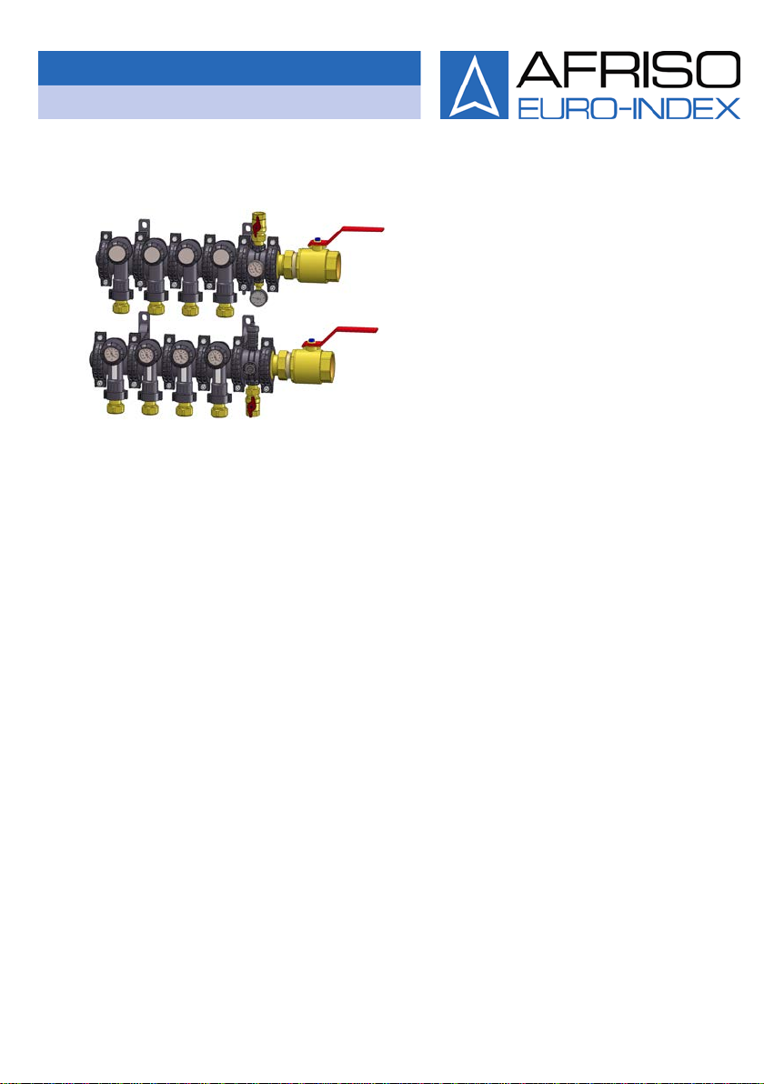
3Product description..................................................................................................6
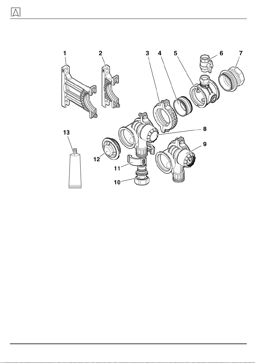
3.1 Components.................................................................................................7
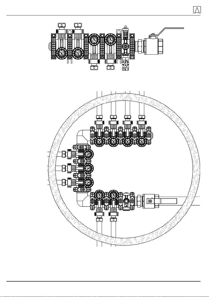
3.2 Application examples ...................................................................................9
4Technical specifications.........................................................................................11
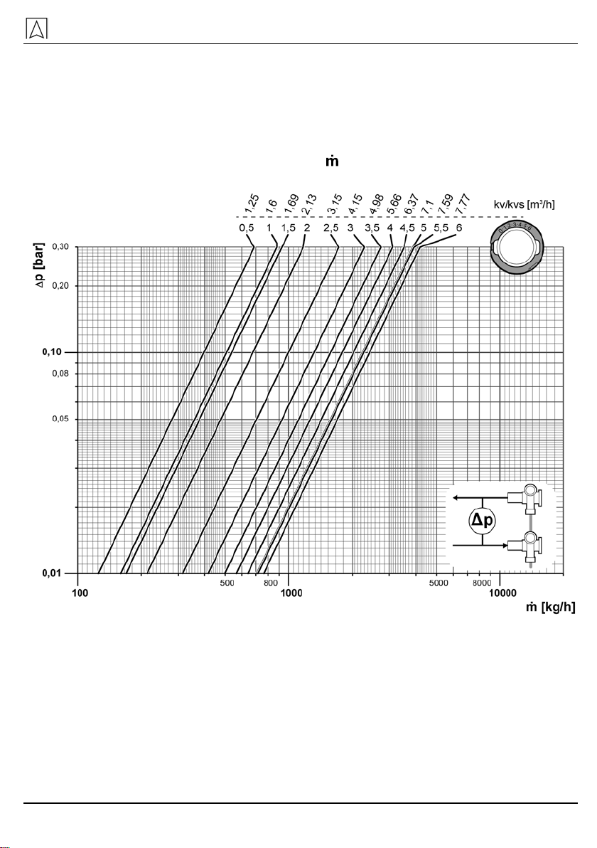
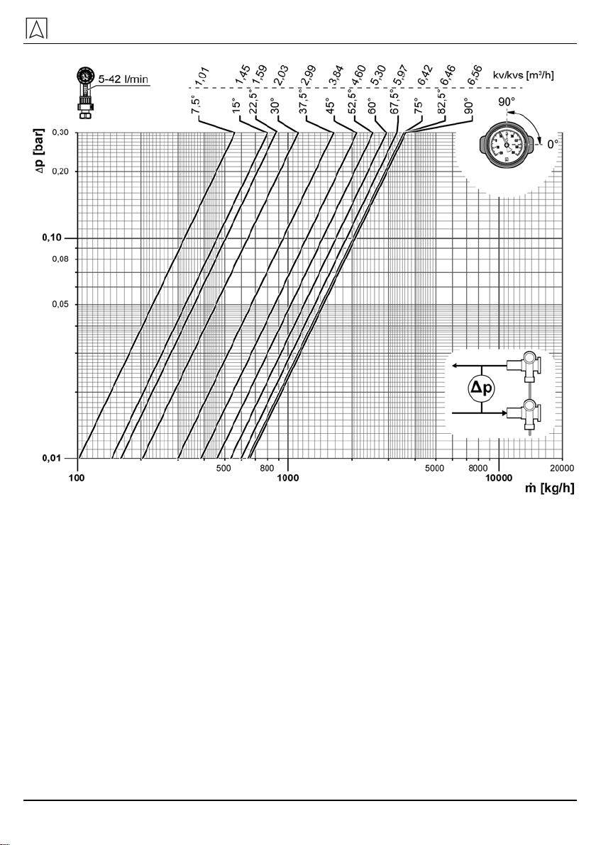
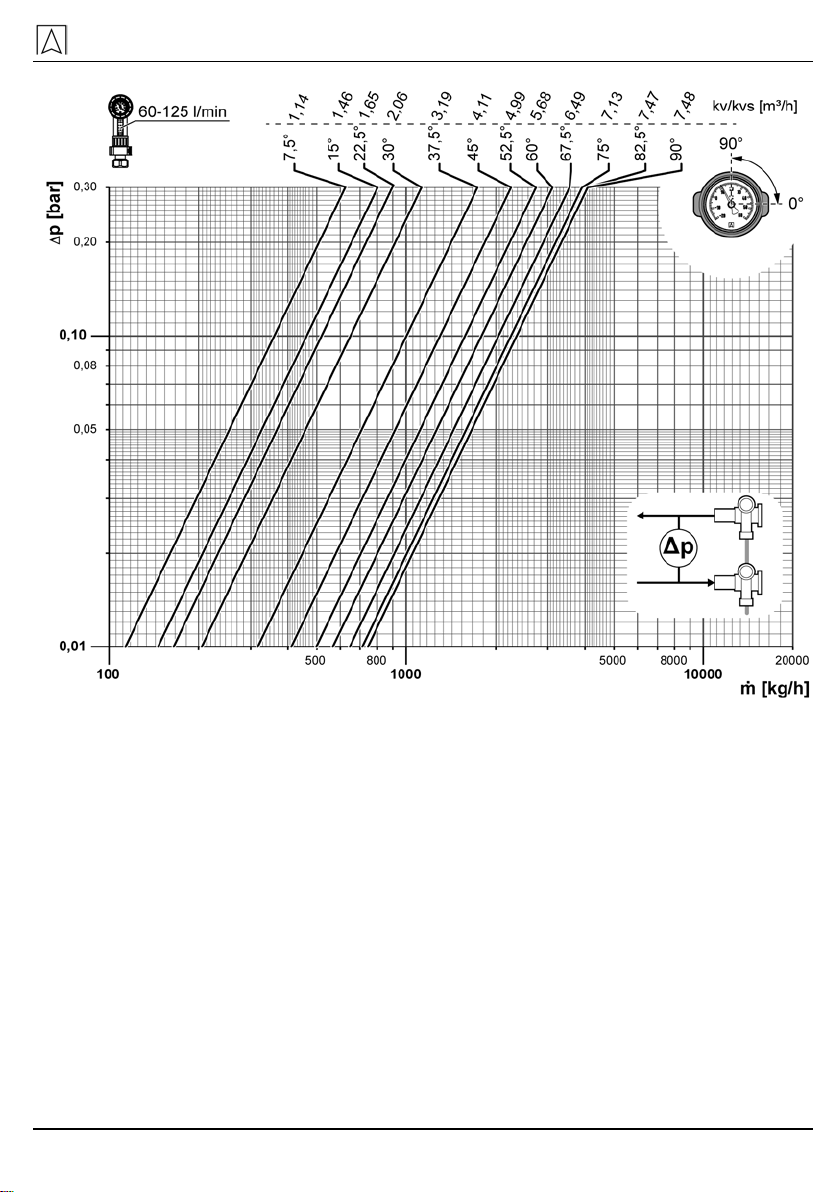
4.1 Charts.........................................................................................................13
5Mounting and commissioning................................................................................18
5.1 Mounting the heating circuit connections...................................................18
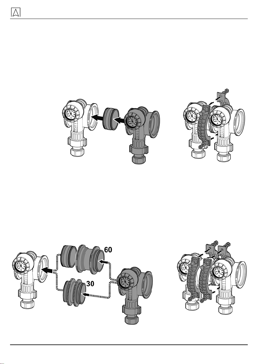
5.2 Pre-assembling the brine/heating circuit manifold.....................................19
5.3 Mounting the brine/heating circuit manifold with wall brackets to the
wall .............................................................................................................21
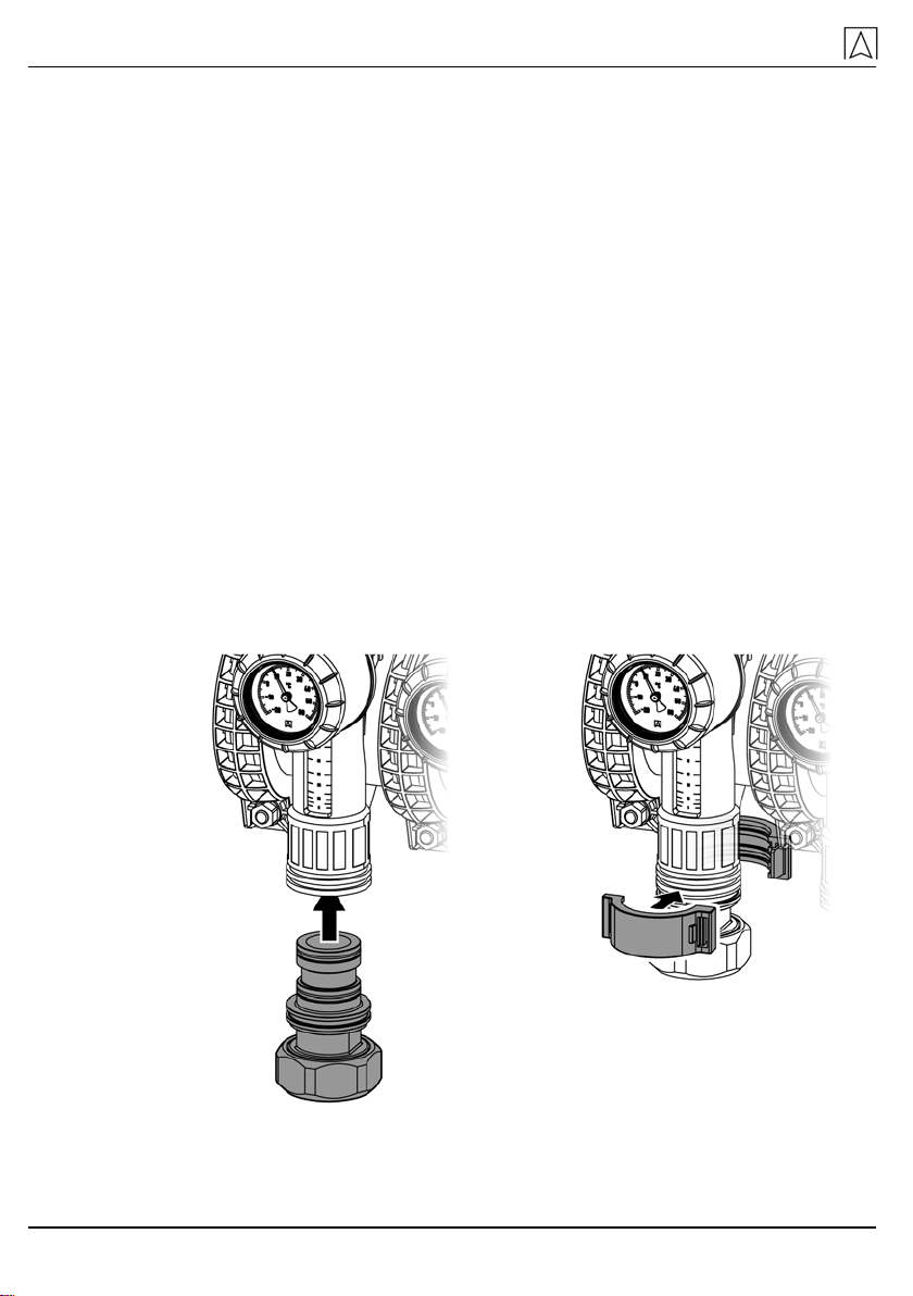
5.4 Mounting the brine/heating circuit connection............................................22
5.5 Filling, flushing and venting the system .....................................................24
5.6 Performing the pressure test and the function test....................................25
5.7 Adjusting the control valves .......................................................................26
5.8 Turning the thermometer (optional) into reading position..........................28
6Copyright ...............................................................................................................28
7Customer satisfaction............................................................................................28
8Addresses..............................................................................................................28

This instruction manual
ProCalida® GT 3 3
1 This instruction manual
This instruction manual is part of the product.
Read this manual before using the product.
Keep this manual during the entire service life of the product
and always have it readily available for reference.
Always hand this manual over to future owners or users of the
product.
1.1 Precautions
WARNING TERM
Type and source of the danger are shown here.
Precautions to take in order to avoid the danger are shown
here.
There are three different levels of warnings:
Warning term Meaning
DANGER Immediately imminent danger!
Failure to observe the information will result in
death or severe injuries.
WARNING Possibly imminent danger!
Failure to observe the information may result in
death or severe injuries.
CAUTION Dangerous situation!
Failure to observe the information may result in
minor or severe injuries as well as damage to
property.
1.2 Explanation of symbols and typeface
Symbol Meaning
Prerequisite for an activity
Activity consisting of a single step
1.
Activity consisting of a several steps
Result of an activity
•
Bulleted list
Text
Indication on display
Highlighting Highlighting

Safety
4 ProCalida® GT 3
2 Safety
2.1 Intended use
The brine/heating circuit manifold ProCalida®GT 3 may only be used
to distribute the following fluids:
•Heating water as per VDI 2035
•Brine (water/glycol mixtures with an admixture of max. 50 %)
Any use other than the application explicitly permitted in this instruc-
tion manual is not permitted.
2.2 Predictable incorrect application
The brine/heating circuit manifold ProCalida®GT 3 must never be
used in the following cases:
•Distribution of drinking water
•Use with adherent, corrosive or flammable fluids
•Operation in solar systems
•Operation in locations subject to direct sunlight
2.3 Safe handling
This product represents state-of-the-art technology and is made ac-
cording to the pertinent safety regulations. Each device is subjected
to a function and safety test prior to shipping.
Operate the product only when it is in perfect condition. Always
observe the operating instructions, all pertinent local and na-
tional directives and guidelines as well as the applicable safety
regulations and directives concerning the prevention of acci-
dents.
2.4 Staff qualification
The product may only be mounted, commissioned, operated, main-
tained, shut down and disposed of by qualified, specially trained
staff.
2.5 Modifications to the product
Changes or modifications made to the product by unauthorised per-
sons may lead to malfunctions and are prohibited for safety reasons.
2.6 Usage of spare parts and accessories
Usage of unsuitable spare parts and accessories may cause dam-
age to the product.
Use only genuine spare parts and accessories of the manufac-
turer.

Safety
ProCalida® GT 3 5
2.7 Liability information
The manufacturer shall not be liable in any form whatsoever for
direct or consequential damage resulting from failure to observe the
technical instructions, guidelines and recommendations.
The manufacturer or the sales company shall not be liable for costs
or damages incurred by the user or by third parties in the usage or
application of this device, in particular in case of improper use of the
device, misuse or malfunction of the connection, malfunction of the
device or of connected devices. The manufacturer or the sales
company shall not be liable for damage whatsoever resulting from
any use other than the use explicitly permitted in this instruction
manual.
The manufacturer shall not be liable for misprints.

Product description
6 ProCalida® GT 3
3 Product description
ProCalida® GT 3 is a modular brine/heating circuit manifold made of
glass-fibre reinforced polyamide. The heating/brine circuits are shut
off by means of shut-off valves at the flow and control valves at the
return. All seals and the fastening material are included.
Fig. 1: ProCalida®GT 3
V Flow R Return

Product description
ProCalida® GT 3 7
3.1 Components
Standard version
Fig. 2: Components standard version
1 Wall bracket long 8 Manifold segment 80/100
with shut-off valve and pro-
tective cover
2 Wall bracket short 9 Manifold segment 80/100
with control valve, flow me-
ter, thermometer and protec-
tive cover
3 Fastener 10 Heating circuit connection
4 Connection element 11 Clamp
5 Multi-way union 12 Blind cover
6 Boiler filling and drain valve
KFE 1" 13 Silicone grease
7 Connection 2½"

Product description
8 ProCalida® GT 3
Accessories
Fig. 3: Components accessories
1 90° elbow 5 Ball valve 2½"
2 Connection element 30 mm 6 Pressure gauge with mount-
ing valve
3 Connection element 60 mm 7 Thermometer
4 Quick air vent
Shut-off valves and control valves
The shut-off valves and control valves when delivered.
Valve open Valve closed

Product description
ProCalida® GT 3 9
3.2 Application examples
Fig. 4: ProCalida GT 3 with four segments 100 mm
Fig. 5: ProCalida GT 3 with nine segments 100 mm
Fig. 6: ProCalida GT 3 with five segments 100 mm and four connec-
tion elements 60 mm

Product description
10 ProCalida® GT 3
Fig. 7: ProCalida GT 3 with four segments 100 mm, connection two
segments from above, two segments from below
Fig. 8: ProCalida GT 3 with nine segments 100 mm and two 90° el-
bows, installation in a shaft

Technical specifications
ProCalida® GT 3 11
4 Technical specifications
Table 1: Technical specifications
Parameters Value
Main connection G2½ with union nut
Possible brine circuit connec-
tions [mm] Compression fitting Ø 25 x 2.3/2.5
Ø 32 x 2.9
Ø 40 x 3.7
Test pressure (24 h, < 30 °C) Max. 6 bar
Operating temperature and
pressure Max. 60 °C at 3 bar
Number of cooling circuits Max. 30
Thermometer -20 °C to +40 °C
0 °C to +60 °C
-20 °C to +60 °C
Flow meter 2-12 l/min
5-42 l/min
35-70 l/min
60-125 l/min

Technical specifications
12 ProCalida® GT 3
Fig. 9: Dimensions [mm]
If identical segments without connection elements 30 mm/60 mm are
used, this results in the following dimensions for A:
Table 2: Dimension A, heating circuits 2 to 20
Brine / heating circuits 2 3 4 5 6 7 8 9 10 11
A[mm] with segment
length 80 mm 320 400 480 560 640 720 800 880 960 1040
A[mm] with segment
length 100 mm 360 460 560 660 760 860 960 1060
1160
1260
Brine / heating circuits 12 13 14 15 16 17 18 19 20 n
A[mm] with segment
length 80 mm 1120
1200
1280
1360
1440
1520
1600
1680
1760
...
A[mm] with segment
length 100 mm 1360
1460
1560
1660
1760
1860
1960
2060
2160
...

Technical specifications
ProCalida® GT 3 13
4.1 Charts Pressure loss curves valve characteristic
Pressure loss curves depending on flow stream and opening angle.
Pressure loss at flow valve considered.
∆
p Pressure loss [mbar] Flow stream [kg/h]
Fig. 10: Diagram for calculating the flow

Technical specifications
14 ProCalida® GT 3
Fig. 11: Pressure loss curves with flow meter 2-12 l/min.

Technical specifications
ProCalida® GT 3 15
Fig. 12: Pressure loss curves with flow meter 5-42 l/min.

Technical specifications
16 ProCalida® GT 3
Fig. 13: Pressure loss curves with flow meter 35-70 l/min.

Technical specifications
ProCalida® GT 3 17
Fig. 14: Pressure loss curves with flow meter 60-125 l/min.

Mounting and commissioning
18 ProCalida® GT 3
5 Mounting and commissioning
Verify that ProCalida GT 3 is not subjected to direct sunlight at
the installation site.
Only mount clean components. Clean polluted components with
a moist piece of cloth. Make sure the sealing surfaces are clean.
Close unused connections with plugs or caps.
Connect pipes to the brine/heating circuit manifold in such a
way that there is no traction, pressure or mechanical tension
(see chapter 4, page 11).
Depending on the on site conditions, the distances between the
wall brackets could be shortened to 400 mm.
Comply with the maximum distances between the wall brackets
and between manifold ends and wall brackets (see chapter 4,
page 11).
5.1 Mounting the heating circuit connections
Grease the O ring.
Insert the heating circuit connection into the segment and lock it
with clamps.

Mounting and commissioning
ProCalida® GT 3 19
5.2 Pre-assembling the brine/heating circuit manifold
Mounting segments
Take into account the position of the wall brackets when mount-
ing the segments (see chapter 4, page 11).
1. Grease the O rings.
2. Insert connection element into segments.
3. Mount the fasteners. Hand-screw the nuts.
Mounting optional connection elements 30 mm/60 mm
Optional connection elements 30 mm/60 mm increase the distance
between two segments by 30 mm/60 mm.
Connection elements 30 mm/60 mm can be combined to increase
the distance between the segments.
1. Grease the O rings.
2. Insert connection element into segments.
3. Mount the fasteners. Hand-screw the nuts.

Mounting and commissioning
20 ProCalida® GT 3
Mounting a blind cover to the end segment
1. Grease the O ring.
2. Insert the blind cover into the segment.
3. Mount the fasteners. Hand-screw the nuts.
Mounting connection segments and end segments to middle
segments
1. Grease the O rings.
2. Put the segment blocks together.
Table of contents
Popular Water System manuals by other brands

Pelican
Pelican Hot Water Post-Filter System Operation guide

Hilti
Hilti DD-WMS 100 Safety sheet

Raritan
Raritan 221551 Installation and maintenance instructions

meibes
meibes KE KELIT Fully Instructions for installation, operation, maintenance

SunEarth
SunEarth SolaRay PV Installation, operation and maintenance manual

Dometic
Dometic SeaXChange XTC Series User manual & installation guide

Crystal Quest
Crystal Quest Water Cooler Installation and maintenance information

Nibe
Nibe SCA 41 Installer manual

Hellenbrand
Hellenbrand 3000 Series Service manual

Davco
Davco SHOP PRO ST Technical manual

Stuart Turner
Stuart Turner Mainsboost MB 100SV Installation, operation & maintenance instructions

GE
GE Merlin Application guide