afx light CITYCOLOR400 User manual

CITYCOLOR400
CODE: 16-2900
GB - PROFESSIONAL OUTDOOR RGBW
WASH PROJECTOR
F - PROJECTEUR WASH PROFESSIONNEL RGBW
POUR L'EXTERIEUR
GB - User Manual - p. 2
F - Manuel d'Utilisation - p. 7
Assembled in PRC
Designed by LOTRONIC S.A.
Av. Z. Gramme 9
B - 1480 Saintes
View the product on our website
USER MANUAL
UNPACKING INSTRUCTIONS
Immediately upon receiving a xture, carefully unpack the carton, check the contents to ensure
that all parts are present and have been received in good condition. Notify the freight company
immediately and retain packing material for inspection if any parts appear to be damaged from
shipping or the carton itself shows signs of mishandling. Keep the carton and all packing mate-
rials. In the event that a xture must be returned to the factory, it is important that the xture be
returned in the original factory box and packing.
CONTENTS OF THE CARTON
• 1 pc. CITYCOLOR400
• 1 pc. user manual
EXPLANATION OF SYMBOLS ON THE SILKSCREEN
The triangle containing a lightning symbol is used to indicate whenever your health is at risk
(due to electrocution, for example).
An exclamation mark in a triangle indicates particular risks in handling or operating the ap-
pliance.
The unit complies with CE standards
0.5m
Minimum distance between the appliance and other objects
CAUTION
DO NOT OPEN THE HOUSING
SHOCK HAZARD
Please read this manual carefully before operating this product.
SAFETY RECOMMENDATIONS
• Please read these instructions carefully, they include important information about the installa-
tion, usage and maintenance of this product.
• Please keep this User Guide for future reference. If you sell the unit to another user, be sure that
he also receives this instruction booklet.
• Always make sure that you are connecting to the proper voltage, and that the line voltage you
are connecting to is not higher than that stated on the bottom of the xture.
• The appliance is part of class I and must exclusively connected to an earthed mains outlet.
• To prevent risk of re or shock, do not expose xture to rain or moisture. Make sure there are no
ammable materials close to the unit while operating.
• The unit must be installed in a location with adequate ventilation, at least 20in (50cm) from
adjacent surfaces. Be sure that no ventilation slots are blocked.
• The minimum distance luminaire from that part of the luminaire or lamp to the lighted object is
0.5m.
0.5m
• The max. ambient temperature (Ta) is 40°C. Don’t operate the xture at higher temperatures.
• DO NOT TOUCH the housing barehand during its operation. Turn off the power and allow about
15 minutes for the unit to cool down before replacing or servicing.
• DO NOT OPEN the unit within 5 minutes after switching off.
• In the event of a serious operating problem, stop using the unit immediately. Never try to repair
the unit by yourself. Repairs carried out by unskilled people can lead to damage or malfunction.
Please contact the nearest authorized technical assistance center. Always use the same type of
spare parts.
• Make sure the power cord is never crimped or damaged.
• Never disconnect the power cord by pulling or tugging on the cord.
• Avoid direct eye exposure to the light source while it is on as sensitive persons may suffer an
EN 2© Copyright LOTRONIC 2019
EN3
www.afx-light.com
epileptic shock (especially meant for epileptics)!.
• The product is for decorative purposes only and not suitable as a household room illumination.
• If the external exible cable or cord of this luminaire is damaged, it shall be exclusively replaced
by the manufacturer or his service agent or a similar qualied person in order to avoid a hazard.
• The lenses, housing or ultraviolet lter must be replaced if they are visibly damaged.
DISCONNECT DEVICE
Where the MAINS plug or an appliance coupler is used as the disconnect device, the disconnect
device shall remain readily operable.
INSTALLATION
The unit should be mounted via its screw holes on the bracket. Always ensure that the unit is rmly
xed to avoid vibration and slipping while operating. Always ensure that the structure to which you
are attaching the unit is secure and is able to support a weight of 10 times of the unit’s weight.
The installation must always be secured with a secondary safety attachment, e.g. an appropriate
safety rope.
Never stand directly below the device when mounting, removing or servicing the xture.
DMX CONNECTION
Connect an XLR cable to the male 3-pin XLR output of your controller and the other side to the fe-
male 3-pin XLR input of the light.You can chain multiple lights together through serial linking
The cable needed should be two core, screened cable with XLR input and output connectors.
DATA CABLING
To link xtures together you must use data cables. If you choose to create your own cable, please
use data-grade cables that can carry a high quality signal and are less prone to electromagnetic
interference.
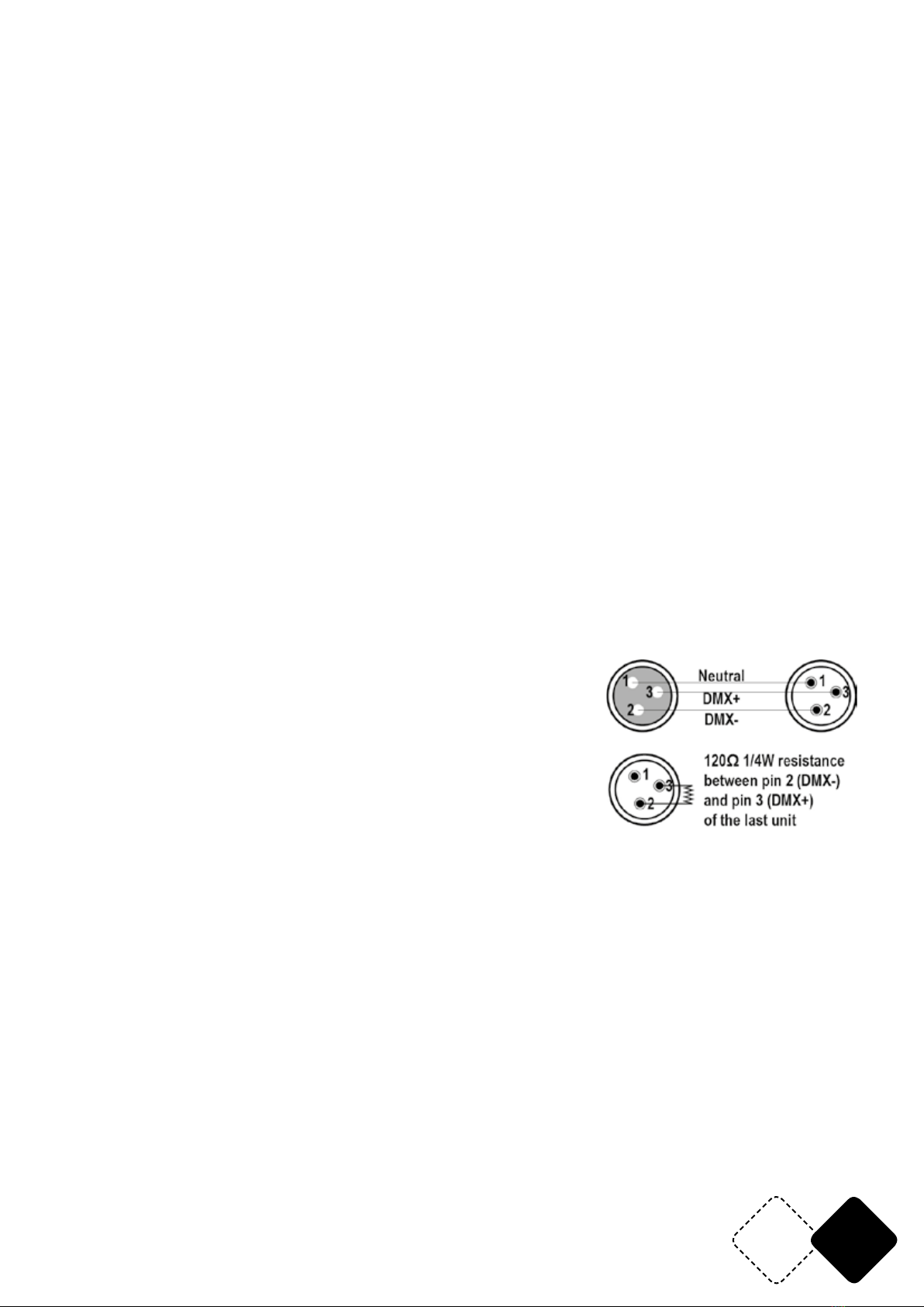
CABLE CONNECTORS
Cabling must have a male XLR connector on one end and a female
XLR connector on the other end.
Termination reduces signal errors. To avoid signal transmission
problems and interference, it is always advisable to connect a DMX
signal terminator.
CAUTION
Do not allow contact between the common and the xture’s chas-
sis ground. Grounding the common can cause a ground loop, and
your xture may perform erratically. Test cables with an ohm meter to check correct polarity and
to make sure the pins are not grounded or shorted to the shield or each other.
FEATURES
• 60x 10W RGBW 4-in-1 LEDs
• Strobe
• 4 / 6 / 9 DMX channels
• 4 dimmer curves
• Auto, Fade & Flash mode with speed control
• Auto or DMX operation
• Waterproof 3-pin XLR connectors
• Powercon True 1 in- and outputs
• 2 x Oméga clamp for installation on a truss
• Seetronic power & DMX leads
EN 4© Copyright LOTRONIC 2019
CONTROL PANEL
The control panel is the mechanism for conguring the settings. It has a small LCD screen and four
buttons, which are described below.
Button Function
<MENU>
Scrolls through the rst level of options, or exits from the current menu or function
<UP>
Navigates upward through the menu list or increases the numeric value when in a function
<DOWN>
Navigates downward through the menu list or decreases the numeric value when in a function
<ENTER>
Enables the currently displayed menu or sets the currently selected value in to the current function
MENU STRUCTURE
1. DMX Address
1. Address Set DMX Address 001~512
2. Channel Mode 4 Channel
6 Channel
9 Channel
2. Manual
1. Dimmer
2. Strobe
3. Red
4. Green
5. Blue
6. White
3. Macro
1. Run Mode: Stop
Flash
Fade
Pulse
2. Speed: 0~255
4. System
1.Host Mode: Off
On
2. Language: English
Chinese
3.Backlight Setting: Auto
Keep on
3.Curve: Curve 1
Curve 2
EN5
www.afx-light.com
Curve 3
Curve 4
4. Blackout Time(ms)
5. Information
1. Device Tou(min)
2. About
DMX CHANNEL FUNCTION AND VALUES
Channels Value Description
4 CH 5 CH 9 CH
1 1 Dimmer
0-255 0-100% Intensity
2 2 Strobe
0-3 No
4-255 Strobe from slow to fast
1 3 3 Red
0-255 0-100% Intensity
2 4 4 Green
0-255 0-100% Intensity
3 5 5 Blue
0-255 0-100% Intensity
4 6 6 White
0-255 0-100% Intensity
7
Color
0-31 None
32-63 Red
64-95 Green
64-95 Green
96-127 Blue
128-159 White
160-191 Red+Green
192-223 Red+Blue
224-255 Green+Blue
8
Macro Function
0-100 None
101-150 Jump
151-200 Fader
200-255 Pulse
9
Speed
Speed
0-255 Speed from slow to fast

EN 6© Copyright LOTRONIC 2019
TROUBLESHOOTING
Following are a few common problems that may occur during operation.Here are some sugges-
tions for easy troubleshooting:
1. The unit does not work,no light and the fan does not work
a. check the connection of power and main fuse.
b. Measure the mains voltage on the main connector.
c. Check the power on Led.
2. Not responding to DMX controller
a. DMX LED should be on. If not, check DMX connectors, cables to see if they link properly.
b. If the DMX LED is on and no response to the channel, check the address settings and DMX pola-
rity.
c. If you have intermittent DMX signal problems, check the pins on connectors or on PCB of the unit
or the previous one.
d. Try to use another DMX controller.
e. Check if the DMX cables run near or run alongside to high voltage cables that may cause damage
or interference to DMX interface circuit.
3. Some units don’t respond to the controller
a. You may have a break in the DMX cabling. Check the LED for the response of the master/slave
mode signal.
b. Wrong DMX address of the unit. Set the proper address.
4. One of the channels is not working well
a. The stepper motor might be damaged or the cable connected to the PCB is broken.
b. The motor’s drive IC on the PCB might be out of condition
5. FIXTURE CLEANING
The cleaning of internal and external optical lenses and/or mirrors must be carried out periodically
to optimize light output. Cleaning frequency depends on the environment in which the xture
operates: damp, smoky or particularly dirty surrounding can cause greater accumulation of dirt
on the unit’s optics.
a. Clean with soft cloth using normal glass cleaning uid.
b. Always dry the parts carefully.
SPECIFICATIONS
Power supply ......................................................................................................................90-240V~ 50/60Hz
Consumption ............................................................................................................................................. 600W
Beam angle .....................................................................................................................................................35°
Photometric data ......................................................81500 Lux @ 1m, 12400 Lux @ 3m, 5020 Lux @ 5m
Light source ......................................................................................................... 60x 10W RGBW 4-in-1 LEDs
Protection class ............................................................................................................................................ IP65
Strobe/pulses .........................................................................................................................1-10 ashes/sec.
Dimensions ........................................................................................................................560 x 130 x 330mm
Weight ....................................................................................................................................................... 15.1kg
IMPORTANT NOTE: Electric products must not be put into household waste. Please bring them to a recycling centre.
Ask your local authorities or your dealer about the way to proceed.
FR7
www.afx-light.com
MANUEL D'UTILISATION
DÉBALLAGE
Dès réception de l’appareil, ouvrez le carton et vériez que le contenu est complet et en bon état.
Sinon, prévenez immédiatement le transporteur et conservez l’emballage s’il montre des signes de
mauvais traitements. Conservez le carton et tous les matériaux d’emballage an de pouvoir trans-
porter l’appareil en toute sécurité.
CONTENU DE L'EMBALLAGE
• 1 pc. CITYCOLOR400
• 1 pc. mode d'emploi
EXPLICATION DES SYMBOLES SUR L'APPAREIL
L’éclair dans le triangle attire l’attention sur un danger physique (due à une électrocution p.
ex.).
Le point d’exclamation dans le triangle indique un risque dans la manipulation ou l’utilisation
de l’appareil.
L'appareil est conforme à la norme CE
0.5m
Distance minimale entre l'appareil et d'autres objets
ATTENTION
NE PAS OUVRIR LE BOITIER
RISQUE DE CHOC ELECTRIQUE
Lire attentivement ce manuel avant la première mise en service.
CONSIGNES DE SECURITE
• Lisez attentivement ce manuel qui contient des informations importantes sur l’installation, l’uti-
lisation et l’entretien de cet appareil.
• Conservez le manuel pour référence ultérieure. Si l’appareil change un jour de propriétaire, assu-
rez-vous que le nouvel utilisateur est en possession du manuel.
• Assurez-vous que la tension secteur convient à cet appareil et qu’elle ne dépasse pas la tension
d’alimentation indiqué sur la plaque signalétique de l’appareil.
• Cet appareil fait partie de la classe I et doit être impérativement branché sur une prise secteur
avec terre.
• An d’éviter tout risque d’incendie ou de choc électrique, ne pas exposer cet appareil à la pluie
ou à l’humidité. Assurez-vous qu’aucun objet inammable ne se trouve à proximité de l’appareil
pendant son fonctionnement.
• Installez l’appareil à un endroit bien ventilé à une distance minimum de 50cm de toute surface.
Assurez-vous que les fentes de ventilation ne sont pas bloquées.
• La distance minimale entre le luminaire et l’objet éclairé doit s’élever à 0,5m..
0.5m
• Ne pas faire fonctionner cet appareil pendant plus de 8 heures en continu. Laissez-le refroidir
avant de l'utiliser à nouveau an de prolonger sa durée de vie.
• Débranchez l’appareil du secteur avant toute manipulation ou entretien.
• La température ambiante ne doit pas dépasser 40°C. Ne pas faire fonctionner l’appareil à des
températures supérieures.
• Ne pas toucher le boîtier les mains nues pendant le fonctionnement. Coupez l'alimentation et
attendez 15 minutes que l'appareil refroidisse avant d'effectuer une intervention.
• NE PAS OUVRIR le boîtier dans les 5 minutes suivant l'arrêt.
• En cas de dysfonctionnement, arrêtez immédiatement l’appareil. N’essayez jamais de réparer
l’appareil par vous-même. Une réparation mal faite peut entraîner des dommages et des dys-
fonctionnements. Contactez un service technique agréé. Utilisez uniquement des pièces déta-
chées identiques aux pièces d’origine.

FR 8© Copyright LOTRONIC 2019
• Assurez-vous que le cordon d’alimentation n’est jamais écrasé ni endommagé.
• Ne jamais débrancher l’appareil en tirant sur le cordon.
• Ne pas exposer vos yeux à la source lumineuse.
• Le luminaire ne doit servir qu’à des ns décoratives et ne convient pas comme éclairage domes-
tique normal.
• Si le cordon secteur de l’appareil est endommagé, il ne doit être remplacé que par le fabricant ou
son agent ou bien un technicien qualié an d’éviter tout risque d’électrocution..
• Remplacez immédiatement les lentilles, le boîtier ou le ltre UV s'ils présentent des dommages.
DISPOSITIF DE COUPURE
Lorsqu’une che SECTEUR ou un coupleur sont utilisés pour déconnecter l’appareil du secteur, ce
dispositif doit rester facilement accessible à tout moment.
INSTALLATION
Fixez l’appareil au moyen des trous de vis sur l’étrier. Assurez-vous que l’appareil est solidement
xé pour éviter des vibrations et des mouvements pendant le fonctionnement. Veillez toujours à ce
que la structure qui accueille l’appareil, est sufsamment solide et capable de porter au moins 10
fois le poids propre de l’appareil.
L’appareil doit être xé par des professionnels à en endroit où il est hors de portée des personnes et
en dehors d’un chemin de passage.
Vous pouvez installer cet appareil dans n’importe quelle position pourvu qu’il y ait une ventilation
sufsante. Lors du choix d’un emplacement, tenez compte de la facilité d’accès à l’appareil pour
des travaux de maintenance et de nettoyage.
Ne jamais installer l’appareil à un endroit exposé à la pluie, l’humidité, aux changements de tem-
pérature importants et présentant une ventilation limitée.
CONNEXION DMX
Branchez le câble XLR sur la sortie mâle de votre contrôleur et l'autre extrémité sur l'entrée femelle
de l'appareil. Vous pouvez ainsi brancher plusieurs appareil en série.
CONNECTEURS DE CABLE
Le câble doit posséder une che XLR mâle d’un côté et XLR femelle de l’autre.
Une résistance de n de ligne réduit les erreurs de signal. Pour
éviter des problèmes de transmission des signaux, il est tou-
jours conseillé de brancher une résistance de n de ligne DMX.
ATTENTION
Il ne doit y avoir aucun contact entre le commun et la masse
du châssis de l’appareil. La mise à la masse du commun peut
provoquer une boucle de masse et votre appareil fonctionne
d’une façon étrange. Testez les câbles à l’aide d’un ohm-mètre
an de vérier la polarité et de vous assurer que les broches
ne sont pas connectées à la masse ni court-circuitées sur le
blindage ou mutuellement.
CARACTERISTIQUES
• 60 LED RGBW 4-en-1 de 10W
• Stroboscope
• 4 / 6 / 9 canaux DMX
• 4 courbes de dimmer
• Mode Auto Fade et Flash avec réglage de la vitesse
• Fonctionnement automatique ou DMX
• Connecteurs XLR étanches à 3 broches
FR9
www.afx-light.com
• Entrées/sorties Powercon True 1
• 2 crochets Oméga pour suspension
• Cordon d'alimentation et DMX Seetronic
TABLEAU DE COMMANDE
Le panneau de commande est l'outil de conguration. Il s'agit d'un petit écran LCD avec quatre
boutons, décrits ci-dessous.
FONCTION DU BOUTON:
<MENU>
Fait déler le premier niveau d'options ou quitter le menu ou la fonction en cours
<UP>
Navigue vers le haut dans la liste de menus ou augmente la valeur numérique dans une fonction
<DOWN>
Navigue vers le bas dans la liste de menus ou diminue la valeur numérique dans une fonction
<ENTER>
Active le menu actuellement afché ou dénit la valeur actuellement sélectionnée sur la fonction
actuelle
STRUCTURE DU MENU
1. Adresse DMX
1. Address Réglage de l'adresse DMX de 001~512
2. Mode canal 4 canaux
6 canaux
9 canaux
2. Manual
1. Dimmer
2. Stroboscope
3. Rouge
4. Vert
5. Bleu
6. Blanc
3. Macro
1. Mode de fonctionnement: Arrêt
FLASH
FAde
Impulsion
2. Vitesse: 0~255
4. Système
1.Host Mode: Off (arrêt)
On (Marche)
2. Language: Anglais
Chinois
FR 10 © Copyright LOTRONIC 2019
3. Réglage du rétroéclairage: Automatique
Rester allumé
3. Courbe: 1. Courbe
2. Courbe
3. Courbe
4. Courbe
4. Durée du blackout (ms)
5. Information
1. Appareil Tou (min)
2. A propos
FONCTION ET VALEURS DES CANAUX DMX
Canaux Valeur Description
4 CH 5 CH 9 CH
1 1 Dimmer
0-255 Intensité 0-100%
2 2 Strobo
0-3 Aucune fonction
4-255 Stroboscope lent rapide
1 3 3 Rouge
0-255 Intensité 0-100%
2 4 4 Vert
0-255 Intensité 0-100%
3 5 5 Bleu
0-255 Intensité 0-100%
4 6 6 Blanc
0-255 Intensité 0-100%
7
Couleur
0-31 Aucune fonction
32-63 Rouge
64-95 Vert
64-95 Vert
96-127 Bleu
128-159 Blanc
160-191 Rouge + Vert
192-223 Rouge + Bleu
224-255 Vert + Bleu
FR11
www.afx-light.com
8
Macro
0-100 Aucune fonction
101-150 Saut
151-200 Fondu
200-255 Impulsion
9
Vitesse
Vitesse
0-255 Vitesse lent rapide
DIAGNOSTIC DE DÉFAILLANCE
Vous trouverez ci-dessous quelques problèmes courants pouvant survenir pendant le fonctionne-
ment. Voici quelques suggestions pour un dépannage simple:
1. L'unité ne fonctionne pas, pas de lumière et le ventilateur ne fonctionne pas
a. vériez le branchement de l'alimentation et du fusible principal.
b. Mesurez la tension du secteur sur le connecteur principal.
c. Vériez le voyant de tension.
2. Ne répond pas au contrôleur DMX
a. La LED DMX devrait être allumée. Sinon, vériez les connecteurs DMX et les câbles pour voir s'ils
sont correctement connectés.
b. Si le voyant DMX est allumé et que le canal ne répond pas, vériez les paramètres d'adresse et
la polarité DMX.
c. Si vous avez des problèmes de signal DMX intermittents, vériez les broches sur les connecteurs
ou sur la carte de circuits imprimés de l'appareil ou du précédent.
d. Essayez d’utiliser un autre contrôleur DMX.
e. Vériez si les câbles DMX se trouvent à proximité de câbles haute tension, ce qui pourrait endom-
mager ou interférer avec le circuit d'interface DMX.
3. Certains appareils ne répondent pas au contrôleur
a. Vous pouvez avoir une rupture dans le câblage DMX. Vériez si le voyant répond au signal du
mode maître / esclave.
b. Mauvaise adresse DMX de l'appareil. Réglez la bonne adresse.
4. Un des canaux ne fonctionne pas bien
a. Le moteur pas à pas est peut-être endommagé ou le câble connecté au circuit imprimé est cassé.
b. Le circuit d’entraînement du moteur sur le circuit imprimé est peut-être en mauvais état
NETTOYAGE DE L'APPAREIL
Le nettoyage des lentilles optiques internes et externes et / ou des miroirs doit être effectué pério-
diquement pour optimiser la puissance lumineuse. La fréquence de nettoyage dépend de l’environ-
nement dans lequel le projecteur fonctionne: Un environnement humide, enfumé ou particulière-
ment sale peut causer une plus grande accumulation de saleté sur les optiques de l'appareil.
a. Nettoyer avec un chiffon doux en utilisant un liquide de nettoyage pour vitres.
b. Toujours sécher les pièces avec soin.
FR 12 © Copyright LOTRONIC 2019
CARACTERISTIQUES TECHNIQUES
Alimentation .......................................................................................................................90-240V~ 50/60Hz
Consommation .......................................................................................................................................... 600W
Angle d'ouverture ...........................................................................................................................................35°
Photométrie .................................................................. 81500 Lux à 1m, 12400 Lux à 3m, 5020 Lux à 5m
Source lumineuse .............................................................................................. 60 LED RGBW 4-en-1 de 10W
Protection...................................................................................................................................................... IP65
Stroboscope/Impulsions ........................................................................................................ 1-10 ashs/sec.
Dimensions ........................................................................................................................560 x 130 x 330mm
Poids .......................................................................................................................................................... 15,1kg
NOTE IMPORTANTE : Les produits électriques ne doivent pas être mis au rebut avec les ordures ménagères. Veuillez les faire recycler
là où il existe des centres pour cela. Consultez les autorités locales ou votre revendeur sur la façon de les recycler.
This manual suits for next models
1
Table of contents
Languages:
Other afx light Projector manuals

afx light
afx light IPAR507 User manual

afx light
afx light FREEPARHEX-BL User manual

afx light
afx light IBOX-H5 User manual

afx light
afx light CLUB-2810-IP User manual

afx light
afx light PROPAR6-HEX User manual

afx light
afx light PROPAR6-WH User manual

afx light
afx light PARCOB100HEX User manual

afx light
afx light IPAR 518 User manual

afx light
afx light PARCOB150WH-MKIII User manual

afx light
afx light PARCOB50WH User manual


