Ag Leader PF3000 User manual


Precision Farming System
PF3000
Operators Manual


PF3000
General
Ag Leader Technology
April 2002
1
-
1
Welcome
Welcome to the Ag Leader Technology family. Ag Leader Technology is
dedicated to the development of advanced, yet practical and cost-effective
tools for grain production. Above all, however, we are dedicated to meeting
your needs for support of existing products and development of product
improvements.
We want to hear from you! Feel free to call any time to discuss:
•Operational problems with your system
•Features you don’t like about your system
•Features you would like added to your system
We will do our best to ensure that you are happy with your current system
and that it is upgraded in the future to better meet your needs.
System Upgrades
Ag Leader Technology will periodically provide free operating program
upgrades that will improve the performance of your PF3000.
To receive free upgrades and new product news, you must send in or fax
(515-232-3595) the Registration Form that is at the beginning of the
operator’s manual. Our mailing address is:
Ag Leader Technology
2202 South Riverside Drive
P.O. Box 2348
Ames, IA 50010
Internet http://www.agleader.com
Limited Warranty
Ag Leader Technology will repair or replace at no charge any component of
the PF3000 system that fails during normal service on the equipment model
that the system was intended for use within two years from the date of first
use.
Warranty is not provided for damage resulting from abuse, neglect,
accidents, vandalism, acts of nature, or any other causes that are outside the
normal, intended use of the PF3000 system.

General
PF3000
Ag Leader Technology
April 2002
1
-
2
Ag Leader Technology shall not be liable for indirect, incidental, or
consequential damages to the dealer, end user, or third parties arising from
the sale, installation, or use of the PF3000 system.
Service
If you have a problem with your system, call your Ag Leader Technology
dealer or call us directly at the phone number below. If we determine you
have a hardware failure, we will ship replacement hardware immediately.
Our mailing address and phone numbers are:
Ag Leader Technology
2202 South Riverside Drive
P.O. Box 2348
Ames, IA 50010
Phone: 515-232-5363
Fax: 515-232-3595
Note:Return failed hardware to us by UPS (preferred) or US mail.
Copyright Notice
Ag Leader Technology has copyrighted (1998) the contents of this
manual and the operating program for the PF3000 system. No reproductions
of this material may be made without first obtaining the consent of Ag
Leader Technology.
Proprietary
Technology Notice
The PF3000 system has patents on its design and operational features.
Copying features of this system relating to measurement and calculation of
grain flow and weight, or organization of field and load data may result in
patent infringement.

PF3000
General
Ag Leader Technology
April 2002
1
-
3
General
Description
The PF3000 is a universal monitor/controller for crop production that is
GPS compatible. It can be transferred from a combine to a tractor or other
vehicles easily. In the combine it functions as a yield monitor and
accurately measures and records acres, moisture, grain weight, bushels, and
yield on-the-go. In the tractor or sprayer it connects to a sprayer or planter
controller and monitors and controls the application rate. The PF3000 also
can record data for field boundaries, tile lines or where a hybrid is planted.
The PF3000 has its own internal memory for recording field and load data.
GPS data, however, is not recorded in the internal memory, but must be
logged to a memory card.
The PF3000 must be setup and calibrated to record accurate information.
NOTE: The Grass Seed version of the PF 3000 is setup and
calibrated using the same procedures as for grain harvest. Where
there are differences between the harvest of grain verses grass seed
they will be noted.
Fields and Loads
All the information recorded by the PF3000 must be recorded in a field and
load. The operator must manually select or change the field and load on the
PF3000 during field operation. A load is used to subdivide a field into
smaller sections. The monitor load is not associated with the combine tank,
wagon, or truck load. It is recommended to use different loads for different
hybrids or varieties or field conditions (like a wet hole).
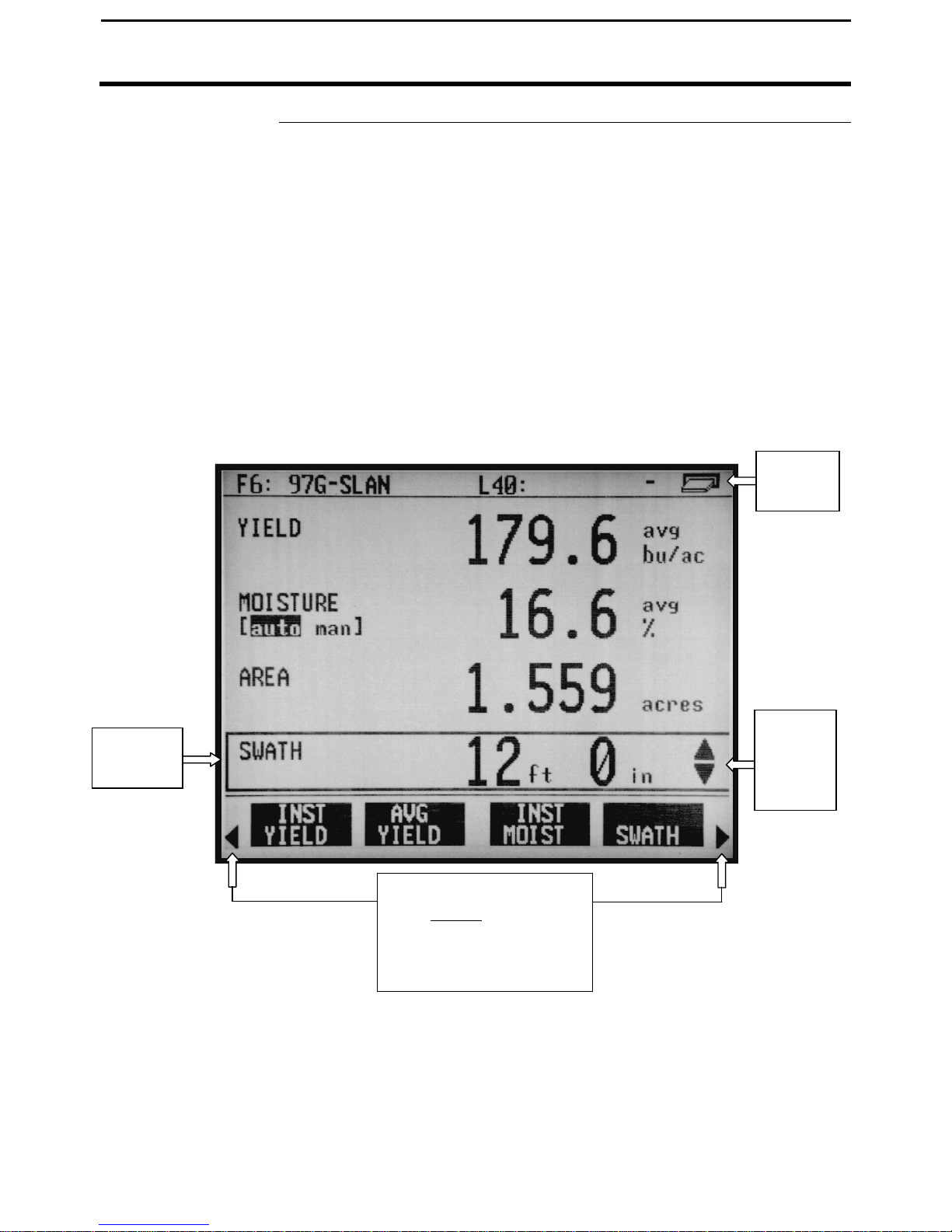
Keypad
The monitor has “soft” keys which do not have labels on the keys to identify
the function of the key. The labels for the keys will appear on the display
screen next to the key. However, there are four major groups of the keys:
arrow keys, display selection keys, menu key, menu selection keys.

General
PF3000
Ag Leader Technology
April 2002
1
-
4
Figure 1: Front panel of the PF3000
Arrow Keys
The UP, DOWN, LEFT and RIGHT ARROW keys on the right side of the
keypad are used to select and change a setting. The bottom LEFT and
RIGHT ARROW keys are only used to view more menu or display items.
They are never used to select or change a setting.
On the main operating screen, you will see an up and down arrow symbol
that will either be beside the field or load or to the right of one of the display
lines. This symbol indicates what item the UP or DOWN ARROW keys
will change if pressed.
Memory
Card Slot
Display
Selection
Keys
Area
Count
Switch
Menu
Key
Menu
Selection
Keys
Arrow
Keys
Power
Switch

PF3000
General
Ag Leader Technology
April 2002
1
-
5
Display and
Display Selection
Keys
The PF3000 has four display lines for viewing items on the main operating
screen. You can choose which items you see on the display and the position
that the items appear on the display.
To change a display item on a display line you must select the line. The four
display selection keys to the right of the display each select a display line. A
rectangular box surrounds the display line to show that it is selected.
When the display line is selected the four menu items on the bottom change
and show items you can select for display. Press a key below one of the
four display items to put a different display item in place of the selected
display item. There are more than four display items to choose for viewing.
Press the bottom LEFT or RIGHT ARROW keys to scroll to the right or left
and view other display items on the bottom.
Figure 2: Main operating screen
When some display items (like swath) are selected, an up and down arrow
Up and
Down
Arrow
Symbol
Selection
Box
When arrows present,
press bottom arrow keys
to display additional
menu or display items
Card
Symbol

General
PF3000
Ag Leader Technology
April 2002
1
-
6
symbol will appear on the right of the display line. This indicates you can
change the setting of the item with the UP or DOWN ARROW keys. After
you have made the change you must press the key to the right of the display
line to deselect the line.
Menu Key
The MENU key switches the menus on the bottom of the display. There are
two main menus that you can view by pressing the MENU key. They are
shown below.
It is recommended to display the FIELD, LOAD, MAP, and OPTIONS
menu during normal operation of the monitor, unless you are marking and
therefore need to display marks on the bottom.
Main Menus:
FIELD
LOAD SHOW
MAP
OPTIONS
CAL
SETUP
DIAG
Menu Selection
Keys
The name above the four menu selection keys on the bottom of the display
will change depending on what you are doing on the monitor.
The bottom RIGHT and LEFT ARROW keys are used to view additional
menu or display items. If you see a right and left arrow symbol on the
display above the bottom RIGHT and LEFT ARROW keys, this indicates
you can press the bottom RIGHT and LEFT ARROW keys to view more
menu or display items. Refer to Figure 2.

PF3000
General
Ag Leader Technology
April 2002
1
-
7
Area Count Switch
The area count switch manually turns on and off area counting. When the
switch is in the up position area is counting. When the switch is in the
down position, area is not counting. The monitor will display either “AREA
ON” or “AREA OFF” on the bottom right corner of the display to indicate
the status of area couting.
Connectors
The PF3000 has four connectors on the bottom side of the console. The
large 25-pin connector is for power and sensor connections. The three 9-pin
ports (Port 1, Port 2, Port 3) are for connecting to a GPS receiver, planter or
fertilizer or sprayer controller or any other GPS compatible device.
Figure 3. PF3000 Connectors
Port 3Port 2Port 1
25-Pin Connector

General
PF3000
Ag Leader Technology
April 2002
1
-
8
Grain Flow Sensor
Below is an example of a grain flow sensor. Your grain flow sensor may
look different, depending on which combine model you have. On all
combines, the grain flow sensor installs on top of the clean grain elevator.
The grain flow sensor measures the grain weight in pounds as you harvest.
The clean grain paddles throw the grain, as the paddles rotate around the top
sprocket, toward the grain flow sensor. The flow sensor measures the grain
weight when the grain strikes the flow sensor impact plate.
NOTE: The flow sensor for grass seed harvest function in the same
manner as the grain flow sensor. The grass seed flow sensor differs
only in appearance.
Figure 4: Grain flow sensor
Grain Flow
Sensor

PF3000
General
Ag Leader Technology
April 2002
1
-
9
Moisture Sensor
Below is an example of the moisture sensor mounted on the side of a clean
grain elevator. The moisture sensor is installed in the elevator mount kit.
Figure 5: Moisture sensor
Moisture Sensor
Elevator
Mount Kit

General
PF3000
Ag Leader Technology
April 2002
1
-
10
Header Height
Sensor
Below is an example of a header height sensor installed underneath a
combine cab. The header height sensor tells the monitor the position of the
combine head so that when the head is raised on the end rows, the monitor
stops counting area.
Figure 6: Header height sensor
* * *
Header Sensor


Setup Overview
PF3000
Ag Leader Technology
April 2002
2
-
2
Important Notices
The PF3000 must be set up before field operation, but before you begin the
setup procedures, read the following notices:
•The PF3000 is a software upgradeable monitor. Ag Leader Technology
will periodically offer free operating program upgrades to increase the
capabilities of the PF3000. To receive the program upgrade, you
must send in the registration form found at the beginning of the
operator’s manual.
•If you plan to make yield maps on your own computer, you will need to
use a mapping program that can process files created by the PF3000.
Section Contents
This setup section contains instructions for the following items. The
operating modes that the instructions pertain to are also listed.
Item Operating Mode Page
Console Setup All 2-6
Card Setup All 2-8
Creating, Naming Fields and Loads All 2-12
Marker Setup All 2-17
GPS Setup All 2-19
Vehicle Setup Harvest 2-30
Grain Setup Harvest 2-34
Swath Setup Harvest 2-39
Swath Setup Site Verification 2-41
Vehicle Site Verification 2-42
Controller Setup Application Rate 2-44
Raven Controller ( with Serial Ports) Application Rate 2-44
Mid-Tech Controller Application Rate 2-49
DICKEY-john Land Manager Application Rate 2-55
DICKEY-john Seed Manager Application Rate 2-61
Rawson Accu-Rate/Accu-Plant Application Rate 2-65
New Leader Mark III/Mark IV Application Rate 2-73
Flexicoil Flexcontrol Application Rate 2-79
Hiniker 8605 Application Rate 2-85
Teejet 844 Application Rate 2-90
Flowmeter Controller Application Rate 2-95
Using Power
Supply
The PF3000 console does not need to be in the vehicle to set it up. You can
use the provided power supply (plugs into 120v outlet) to power up the

PF3000
Setup Overview
Ag Leader Technology
April 2002
2
-
3
console inside your home or shop.


PF3000
Setup Overview
Ag Leader Technology
All Modes
April 2002
2
-
3
Order of Keys
(Harvest Mode)
Press the MENU key until you see the following keys on
the display.
SUMMARY
CAL
SETUP
DIAG
Press the SETUP key to view the
following setup menu items.
SETUP
OPTIONS
PRESS TO EXIT
SWATH
MARKS
GRAIN
CARD
LOAD
VEHICLE
CONSOLE
MEMORY
GPS
MAP
Press the bottom LEFT or RIGHT ARROW keys to
switch between and view the setup menu items
shown above.

Setup Overview
PF3000
All Modes
Ag Leader Technology
April 2002
2
-
4
Order of Keys
(Site Verification
Mode)
Press MENU key
the display.
Until you see the following keys on the
CAL
SETUP
DIAG
Press the SETUP key to view
the following setup menu items.
SETUP
OPTIONS
PRESS TO EXIT
SWATH
MARKS
CARD
LOAD
VEHICLE
CONSOLE
MEMORY
GPS
MAP
Press the bottom LEFT or RIGHT ARROW keys to
switch between and view the setup menu items
shown above.
Table of contents