5
SERVICING - WARNING
Disconnect from electricity and gas before servicing. Check appliance is safe when you have finished.
5. To Remove Oven Light Switch
Remove control panel (see 2).
NB The old switch may be destroyed during
removal.
Remove switch button and old switch from its
bezel by gripping the switch body behind the
control panel and twisting sharply.
The switch bezel can then be removed by folding
back its locking wings and pushing forward. Fit
the new bezel to the control panel by first lining
up the raised key on its body with the cutout in
the control panel and pushing it in from the front.
Assemble the new switch to the bezel by lining up
the key sections and pushing home. Fit the new
button by pushing in from the front.
Replace control panel in reverse order and test for
correct operation.
6. To Remove Electronic Timer
Disconnect from electricity supply.
Pull off the timer control buttons and remove
the control panel (See 2). Remove the timer/
mounting bracket assembly from the control panel
by removing the two fixing screws. Remove the
timer from its mounting bracket by depressing the
plastic lugs on the timer case, at the same time
pulling the unit forward.
Reassemble in reverse order. When replacing
leads refer to the wiring diagram. Check operation
of timer.
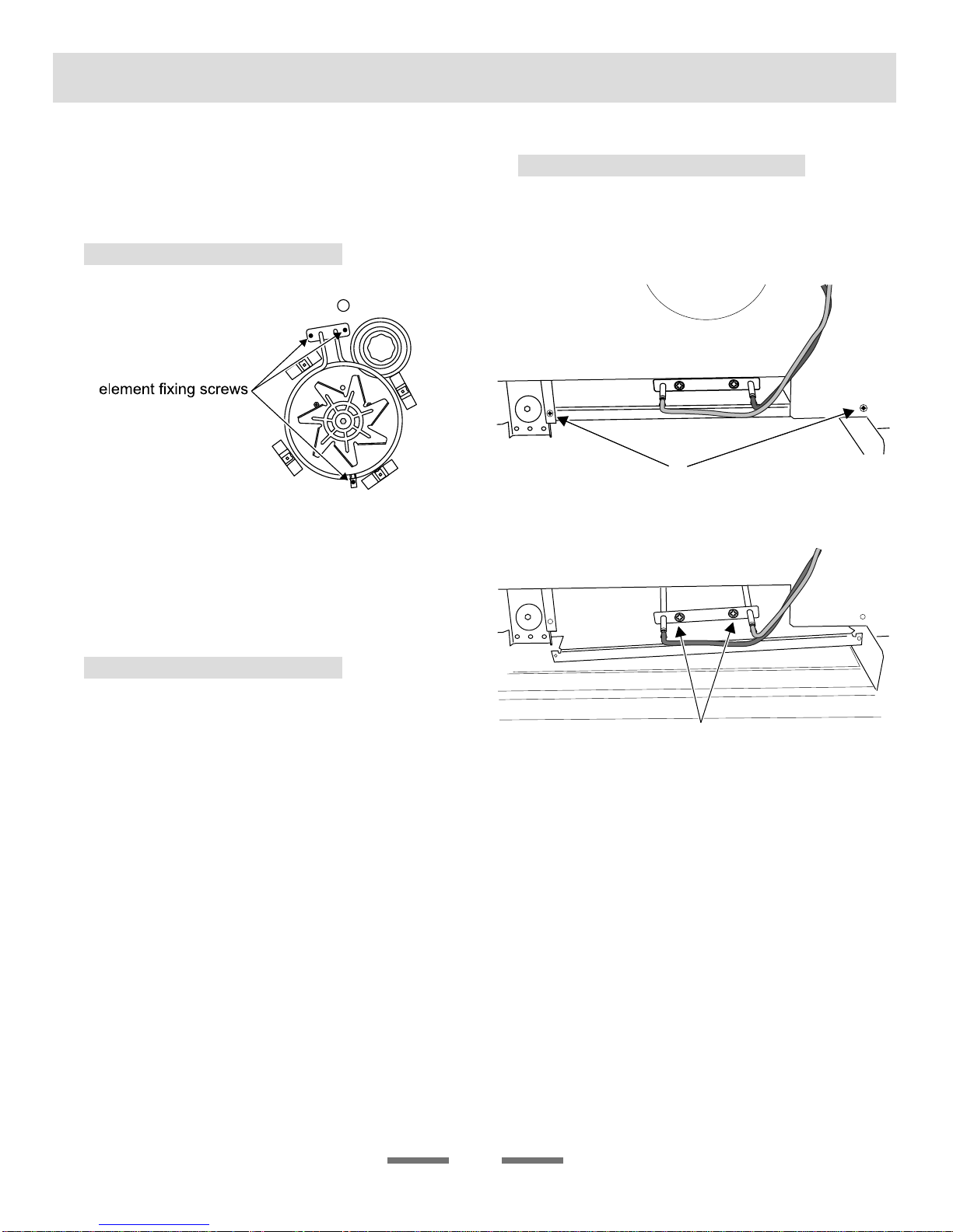
7. To Remove a Thermostat
Remove control panel (see 2) and cooktop (see
3). Open the appropriate oven door and remove
the oven shelves.
Right-hand oven
Remove oven roof. Remove the two fixings that
secure the thermostat phial cover. Unclip the
thermostat phial from the clips in the oven back
panel & remove from the top rear of the oven.
Left-hand oven
Remove the two screws holding the thermostat
phial to the oven fan cover at the rear of the
oven. Pull the unit forward to access the rear
of the cooker. Remove both rear cover boxes
by removing the fixing screws and lifting clear.
Feed the thermostat capillary clear of the oven.
Disconnect the wires from the thermostat and
undo the two fixings that secure the control to
the mounting plate. Fit the replacement and re-
assemble in reverse order. Ensure that the phial
is clipped to the oven rear, positioned centrally
between the clips. Check that the thermostat
functions correctly.
8. To Change Broiler Controller
Remove the control panel (see 2) and cooktop
(see 3). Disconnect wiring from controller. Remove
2 screws holding switch/controller to mounting
panel. Fit new controller and reassemble in
reverse order. Check for correct operation.
BEFORE SERVICING ANY GAS CARRYING
COMPONENTS TURN OFF GAS SUPPLY.
9. To Change a Cooktop Tap
Remove the cooktop top, see 3. Undo the nut
at rear of the valve and remove the screw(s)
securing valve to gas rail. Remove old valve,
discard old gasket/seal. Fit new gasket/seal to
new valve.
Reassemble in reverse order. Check valve is
adjusted for correct gas. Check cooker is gas
sound.
10. To Change a Cooktop Burner Orifice
StandardburnerWokburner
ArtNo.102-0014 - Burner details
A
B
C
Aorice,Binternalorice,Cexternalorice
Remove burner cap and head. Remove old orifice.
Fit new orifice. Note the Wok burner has 2 orifices.
Reassemble in reverse order. Check appliance is
gas sound.
11. To Change Cooktop Burner
Electrode
Lift off hoplate pan supports, remove burner
cap. Remove the screw holding the electrode.
Pull electrode vertically up sufficiently to grip
the lead between thumb and forefinger. Pull off
the electrode, but keep hold of the lead. Fit new
electrode to the lead. Fix electrode in burner with