6 7713402 R0
Dryer Model Number
D Series Model Numbers
The dryer model number provides information on the dryer length and capacity.
• The two digits after “D" are the dryer length.
• Multiply the remaining digits by 10 to determine the approximate bushel capacity for corn. In this example:
40 x 10 = 400 bushels
Example: D 16 60
•16 indicates this model is a 16 foot long dryer
•60 indicates this model has a capacity of 60 x 10 = 600 bushels
Using the same process, a model D32500 would be a 32 foot long dryer with an approximate capacity of 5,000
bushels.
K Series Model Number
The three digits after “K” indicate the nominal storage capacity. For example, a K600 holds approximately 600
bushels of grain.
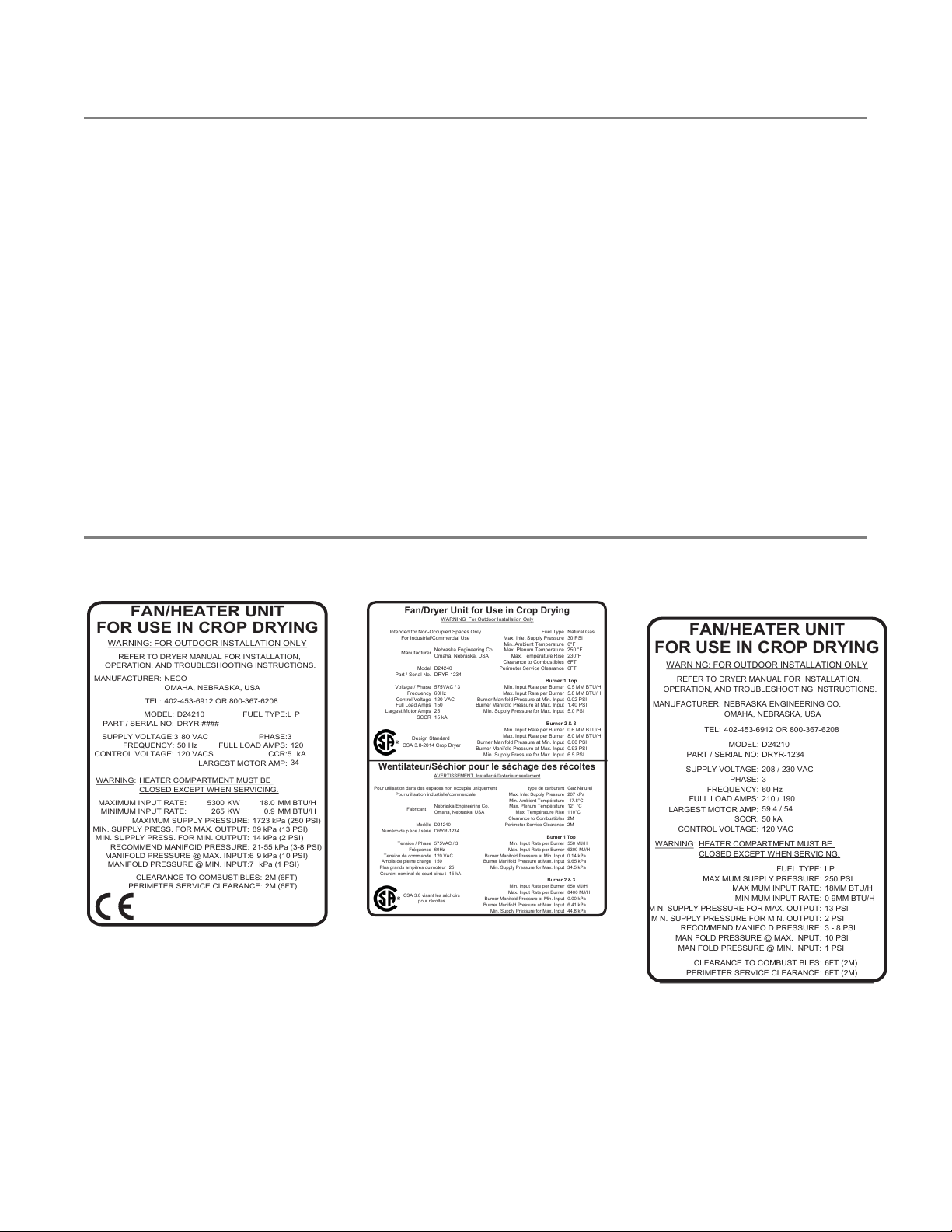
Dryer Rating Label
Figure 1. Dryer Rating Label — CE
MODEL: D24210 FUEL TYPE:L P
PART / SERIAL NO: DRYR-####
SUPPLY VOLTAGE:3 80 VAC PHASE:3
FREQUENCY: 50 Hz FULL LOAD AMPS:
CONTROL VOLTAGE: 120 VACS CCR:5 kA
LARGEST MOTOR AMP:
WARNING:
CLOSED EXCEPT WHEN SERVICING.
MAXIMUM INPUT RATE: KW MM BTU/H
MINIMUM INPUT RATE: KW MM BTU/H
MAXIMUM SUPPLY PRESSURE: 1723 kPa (250 PSI)
MIN. SUPPLY PRESS. FOR MAX. OUTPUT: 89 kPa (13 PSI)
MIN. SUPPLY PRESS. FOR MIN. OUTPUT: 14 kPa (2 PSI)
RECOMMEND MANIFOID PRESSURE: 21-55 kPa (3-8 PSI)
MANIFOLD PRESSURE @ MAX. INPUT:6 9 kPa (10 PSI)
MANIFOLD PRESSURE @ MIN. INPUT:7 kPa (1 PSI)
CLEARANCE TO COMBUSTIBLES: 2M (6FT)
PERIMETER SERVICE CLEARANCE: 2M (6FT)
402-453-6912 OR 800-367-6208
HEATER COMPARTMENT MUST BE
120
34
FAN/HEATER UNIT
FOR USE IN CROP DRYING
WARNING: FOR OUTDOOR INSTALLATION ONLY
REFER TO DRYER MANUAL FOR INSTALLATION,
OPERATION, AND TROUBLESHOOTING INSTRUCTIONS.
MANUFACTURER:
TEL:
NECO
OMAHA, NEBRASKA, USA
0.9
18.0
5300
265
Figure 2. Dryer Rating Label — CSA
Intended for Non-Occupied Spaces Only
For Industrial/Commercial Use
Max. Inlet Supply Pressure 30 PSI
Min. Ambient Temperature 0°F
Nebraska Engineering Co. Max. Plenum Temperature 250 °F
Omaha, Nebraska, USA Max. Temperature Rise
Clearance to Combustibles 6FT
Model D24240 Perimeter Service Clearance 6FT
Part / Serial No. DRYR-1234
Voltage / Phase 575VAC / 3 Min. Input Rate per Burner 0.5 MM BTU/H
Frequency 60Hz Max. Input Rate per Burner 5.8 MM BTU/H
Control Voltage 120 VAC Burner Manifold Pressure at Min. Input 0.02 PSI
Full Load Amps 150 Burner Manifold Pressure at Max. Input 1.40 PSI
Min. Supply Pressure for Max. Input
Min. Input Rate per Burner 0.6 MM BTU/H
Max. Input Rate per Burner 8.0 MM BTU/H
Burner Manifold Pressure at Min. Input 0.00 PSI
Burner Manifold Pressure at Max. Input 0.93 PSI
Min. Supply Pressure for Max. Input
Pour utilisation dans des espaces non occupés uniquement type de carburant
Pour utilisation industielle/commerciale Max. Inlet Supply Pressure
Min. Ambient Température -17.8°C
Nebraska Engineering Co. Max. Plenum Température 121 °C
Omaha, Nebraska, USA Max. Température Rise 110°C
Clearance to Combustibles 2M
Modèle D24240 Perimeter Service Clearance 2M
Numéro de p èce / série DRYR-1234
Tension / Phase 575VAC / 3 Min. Input Rate per Burner 550 MJ/H
Fréquence 60Hz Max. Input Rate per Burner 6300 MJ/H
Tension de commande 120 VAC Burner Manifold Pressure at Min. Input 0.14 kPa
Amplis de pleine charge 150 Burner Manifold Pressure at Max. Input 9.65 kPa
Plus grands ampères du moteur 25 Min. Supply Pressure for Max. Input 34.5 kPa
Courant nominal de court-circu t 15 kA
Min. Input Rate per Burner 650 MJ/H
Max. Input Rate per Burner 8400 MJ/H
Burner Manifold Pressure at Min. Input 0.00 kPa
Burner Manifold Pressure at Max. Input 6.41 kPa
Min. Supply Pressure for Max. Input 44.8 kPa
Fan/Dryer Unit for Use in Crop Drying
WARNING For Outdoor Installation Only
Wentilateur/Séchior pour le séchage des récoltes
AVERTISSEMENT Installer á l'extérieur seulement
CSA 3.8 visant les séchoirs
pour récoltes
Design Standard
CSA 3.8-2014 Crop Dryer
Figure 3. Dryer Rating Label —
Domestic
MODEL: D24210
PART / SERIAL NO: DRYR-1234
SUPPLY VOLTAGE:
PHASE: 3
FREQUENCY: 60 Hz
FULL LOAD AMPS:
LARGEST MOTOR AMP:
SCCR: 50 kA
CONTROL VOLTAGE: 120 VAC
CLOSED EXCEPT WHEN SERVIC NG.
FUEL TYPE: LP
MAX MUM SUPPLY PRESSURE: 250 PSI
MAX MUM INPUT RATE:
MIN MUM INPUT RATE: 0 9MM BTU/H
M N. SUPPLY PRESSURE FOR MAX. OUTPUT: 13 PSI
M N. SUPPLY PRESSURE FOR M N. OUTPUT: 2 PSI
RECOMMEND MANIFO D PRESSURE: 3 - 8 PSI
MAN FOLD PRESSURE @ MAX. NPUT: 10 PSI
MAN FOLD PRESSURE @ MIN. NPUT: 1 PSI
CLEARANCE TO COMBUST BLES: 6FT (2M)
PERIMETER SERVICE CLEARANCE: 6FT (2M)
WARN NG: FOR OUTDOOR INSTALLATION ONLY
REFER TO DRYER MANUAL FOR NSTALLATION,
OPERATION, AND TROUBLESHOOTING NSTRUCTIONS.
402-453-6912 OR 800-367-6208
HEATER COMPARTMENT MUST BE
1. GENERAL DESIGN CRITERIA CONTINUOUS MIXED-FLOW GRAIN DRYER – GRAIN DRYER