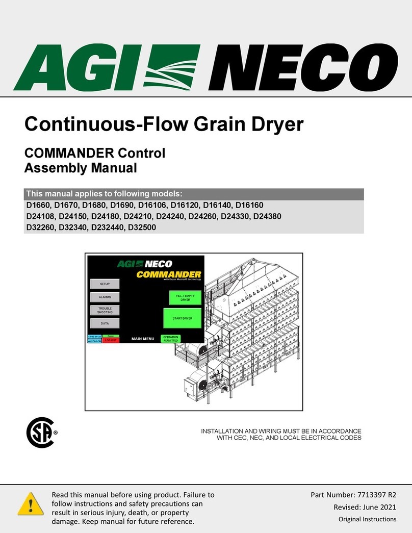
AGI NECO D1660 User manual

Read this manual before using product. Failure to
follow instructions and safety precautions can
result in serious injury, death, or property
damage. Keep manual for future reference.
Part Number: 7713395 R2
Revised: November 2021
Original Instructions
Continuous Mixed-Flow Grain
Dryer with COMMANDER Control
System
Operator’s Manual
This manual applies to the following models:
D1660, D1670, D1680, D1690, D16106, D16120, D16140, D16160
D24108, D24150, D24180, D24210, D24240, D24260, D24330, D24380
D32260, D32340, D232440, D32500
Original Instructions

This product has been designed and manufactured to meet general engineering standards. Other local
regulations may apply and must be followed by the operator. All personnel must be trained in the correct
operational and safety procedures for this product. Use the sign-off sheet below to record initial and periodic
reviews of this manual with all personnel.
Date Employee Name and Signature Employer Name and Signature

CONTINUOUS MIXED-FLOW GRAIN DRYER WITH COMMANDER CONTROL SYSTEM
7713395 R2 3
CONTENTS
1. Introduction ............................................................................................................................................ 6
1.1 Product Information.................................................................................................................. 6
1.2 Intended Use ............................................................................................................................. 7
1.2.1 Misuse ........................................................................................................................ 7
2. Safety....................................................................................................................................................... 8
2.1 Safety Alert Symbol and Signal Words...................................................................................... 8
2.2 General Safety Information....................................................................................................... 8
2.3 Overhead Power Lines .............................................................................................................. 8
2.4 Grain Dryer Safety ..................................................................................................................... 9
2.5 Gas Leak Hazards..................................................................................................................... 10
2.6 Guards Safety .......................................................................................................................... 10
2.7 Work Area Safety .................................................................................................................... 10
2.8 Drives and Lockout/Tagout Safety .......................................................................................... 10
2.8.1 Electric Motor Safety................................................................................................ 11
2.9 Personal Protective Equipment............................................................................................... 11
2.10 Safety Equipment .................................................................................................................. 12
2.11 Safety Decals ......................................................................................................................... 12
2.12 Decal Installation/Replacement............................................................................................ 12
2.13 Safety Decal Locations and Details ....................................................................................... 13
3. Features................................................................................................................................................. 19
3.1 General Design Criteria ........................................................................................................... 19
3.1.1 Tier Information ....................................................................................................... 19
3.1.2 Body Section Information ........................................................................................ 19
3.1.3 Standard Lengths...................................................................................................... 19
3.1.4 Total Tier Levels per Length..................................................................................... 19
3.1.5 Dryer Model Number ............................................................................................... 20
3.1.6 Dryer Rating Label .................................................................................................... 20
3.2 Parts of the Dryer.................................................................................................................... 21
3.2.1 Front of Dryer........................................................................................................... 21
3.2.2 Rear of Dryer ............................................................................................................ 23
3.2.3 Catwalk Positions ..................................................................................................... 24
3.3 Fuel Supply Components......................................................................................................... 25
3.3.1 Liquid Propane (LP) .................................................................................................. 25
3.3.2 Natural Gas (NG) ...................................................................................................... 30
3.4 Burner Control and Temperature Control .............................................................................. 31
3.5 Blower System......................................................................................................................... 34
3.6 Grain Cooling System (optional) ............................................................................................. 35
3.7 Grain Level Switches................................................................................................................ 36
3.8 Discharge Equipment .............................................................................................................. 42
3.9 Commander Control Components .......................................................................................... 51
3.9.1 Main Control Box ..................................................................................................... 51
PLC Details ......................................................................................................................... 52
3.9.2 HMI Enclosure .......................................................................................................... 53
3.9.3 Moisture/Temperature Sensor Overview................................................................ 55
3.9.4 Discharge Plugged Sensor ........................................................................................ 58
3.10 External Transport(s)............................................................................................................. 59

CONTINUOUS MIXED-FLOW GRAIN DRYER WITH COMMANDER CONTROL SYSTEM
4 7713395 R2
4. Operation .............................................................................................................................................. 60
4.1 Operation Safety ..................................................................................................................... 60
4.2 Equipment Pre-Check.............................................................................................................. 60
4.3 Commander Control Setup ..................................................................................................... 63
4.3.1 Log In ........................................................................................................................ 63
4.3.2 SETUP Main Screen .................................................................................................. 68
4.3.3 NECO Entered Setup Data........................................................................................ 70
4.3.4 Dealer or Customer Entered Setup Data ................................................................. 73
4.4 Operation Overview ................................................................................................................ 77
4.4.1 Example A: Batch Drying .......................................................................................... 78
4.4.2 Example B: Auto Drying ........................................................................................... 78
4.4.3 Plenum Door Safety Switch...................................................................................... 79
4.5 Fill/Empty Dryer ...................................................................................................................... 80
4.6 Start Dryer - Main.................................................................................................................... 83
4.6.1 Start Dryer Overview................................................................................................ 83
4.6.2 Completion of Dryer Setup ...................................................................................... 89
4.6.3 To Start Batch Drying ............................................................................................... 89
4.7 Batch Drying Mode.................................................................................................................. 90
4.7.1 Batch Drying Overview............................................................................................. 90
4.8 Auto Drying Mode ................................................................................................................... 94
4.8.1 Auto Drying Pre-Conditions ..................................................................................... 94
4.8.2 Auto Drying Overview .............................................................................................. 95
4.8.3 Slide Gate Adjustment ........................................................................................... 102
4.8.4 Moisture Calibration .............................................................................................. 105
4.9 Data and Graphs Screens ...................................................................................................... 107
4.9.1 Data Screen ............................................................................................................ 107
4.9.2 Performance Data Graphs...................................................................................... 108
4.10 Emergency Shutdown Procedure........................................................................................ 110
5. Maintenance ....................................................................................................................................... 112
5.1 Maintenance Safety .............................................................................................................. 112
5.2 Maintenance Overview ......................................................................................................... 112
5.3 Burner Gas Ports ................................................................................................................... 113
5.4 Solenoid Valves ..................................................................................................................... 113
5.5 Lubrication............................................................................................................................. 114
5.6 Motors ................................................................................................................................... 114
6. Troubleshooting.................................................................................................................................. 115
6.1 Solutions Table ...................................................................................................................... 115
6.2 HMI Troubleshooting Screens............................................................................................... 119
7. Specifications ...................................................................................................................................... 125
7.1 Standard Model Specifications ............................................................................................. 125
8. Appendix ............................................................................................................................................. 127
8.1 Manual Dryer Speed.............................................................................................................. 127
8.2 Optional External Transport Configurations ......................................................................... 128
8.3 Wiring External Transports ................................................................................................... 132
8.4 Wiring NEMA Starters / IEC Starters / Air Systems............................................................... 133
8.5 PLC and HMI Recorded Data Sheet....................................................................................... 134
8.6 Updating the PLC and HMI Programs ................................................................................... 135
8.7 Main Control Box Terminal Strip........................................................................................... 138

CONTINUOUS MIXED-FLOW GRAIN DRYER WITH COMMANDER CONTROL SYSTEM
7713395 R2 5
8.8 Honeywell Burner Control Fault Codes................................................................................. 139
8.9 KS45 & TB45 Controller LEDs ................................................................................................ 140
8.10 HMI Wiring Connections ..................................................................................................... 146
8.11 DryerMaster Moisture Sensor Circuit Board ...................................................................... 148
8.12 Commander Wi-Fi access (Vijeo Air App) ........................................................................... 149
8.13 Dryer Temperature Considerations .................................................................................... 150
8.14 Grain Drying Tips ................................................................................................................. 152
8.14.1 Specific Crops ....................................................................................................... 152
8.14.2 Measuring Actual Seed Temperatures ................................................................ 156
9. Compliance.......................................................................................................................................... 157
10. Limited Warranty.............................................................................................................................. 159

6 7713395 R2
1. Introduction
Thank you for your purchase. Follow the instructions in this manual for safe use of this grain dryer.
Following proper operation and maintenance will help to keep the grain dryer running in optimal
condition.
Keep this manual handy for frequent reference and to review with new personnel. A sign-off form is
provided on the inside front cover for your convenience. If any information in this manual is not
understood or if you need additional information, please contact AGI or your representative for
assistance.
This manual should be regarded as part of the equipment.
1.1. Product Information
Always give your dealer the following product information when ordering parts or requesting service. Please
record the product information in the table below for easy reference.
Local Dealer’s Name and Address: Phone:
Local Contractor’s Name: Phone:
Service Contractor’s Name: Phone:
Purchase Date: Installation Date:
Model Number: Serial Number:
Fuel Type: Number of Blowers:
Wiring Diagram Drawing Number:
Figure 1. Dryer Rating Label — CE
MODEL: D24210 FUEL TYPE:L P
PART / SERIAL NO: DRYR-####
SUPPLY VOLTAGE:3 80 VAC PHASE:3
FREQUENCY: 50 Hz FULL LOAD AMPS:
CONTROL VOLTAGE: 120 VACS CCR:5 kA
LARGEST MOTOR AMP:
WARNING:
CLOSED EXCEPT WHEN SERVICING.
MAXIMUM INPUT RATE: KW MM BTU/H
MINIMUM INPUT RATE: KW MM BTU/H
MAXIMUM SUPPLY PRESSURE: 1723 kPa (250 PSI)
MIN. SUPPLY PRESS. FOR MAX. OUTPUT: 89 kPa (13 PSI)
MIN. SUPPLY PRESS. FOR MIN. OUTPUT: 14 kPa (2 PSI)
RECOMMEND MANIFOID PRESSURE: 21-55 kPa (3-8 PSI)
MANIFOLD PRESSURE @ MAX. INPUT:6 9 kPa (10 PSI)
MANIFOLD PRESSURE @ MIN. INPUT:7 kPa (1 PSI)
CLEARANCE TO COMBUSTIBLES: 2M (6FT)
PERIMETER SERVICE CLEARANCE: 2M (6FT)
402-453-6912 OR 800-367-6208
HEATER COMPARTMENT MUST BE
120
34
FAN/HEATER UNIT
FOR USE IN CROP DRYING
WARNING: FOR OUTDOOR INSTALLATION ONLY
REFER TO DRYER MANUAL FOR INSTALLATION,
OPERATION, AND TROUBLESHOOTING INSTRUCTIONS.
MANUFACTURER:
TEL:
NECO
OMAHA, NEBRASKA, USA
0.9
18.0
5300
265
Figure 2. Dryer Rating Label — CSA
Intended for Non-Occupied Spaces Only
Fuel Type Natural Gas
For Industrial/Commercial Use
Max. Inlet Supply Pressure 30 PSI
Min. Ambient Temperature 0°F
Nebraska Engineering Co. Max. Plenum Temperature 250 °F
Omaha, Nebraska, USA Max. Temperature Rise
230°F
Clearance to Combustibles 6FT
Model D24240 Perimeter Service Clearance 6FT
Part / Serial No. DRYR-1234
Burner 1 Top
Voltage / Phase 575VAC / 3 Min. Input Rate per Burner 0.5 MM BTU/H
Frequency 60Hz Max. Input Rate per Burner 5.8 MM BTU/H
Control Voltage 120 VAC Burner Manifold Pressure at Min. Input 0.02 PSI
Full Load Amps 150 Burner Manifold Pressure at Max. Input 1.40 PSI
Largest Motor Amps
25
Min. Supply Pressure for Max. Input
5.0 PSI
SCCR
15 kA
Burner 2 & 3
Min. Input Rate per Burner 0.6 MM BTU/H
Max. Input Rate per Burner 8.0 MM BTU/H
Burner Manifold Pressure at Min. Input 0.00 PSI
Burner Manifold Pressure at Max. Input 0.93 PSI
Min. Supply Pressure for Max. Input
6.5 PSI
Pour utilisation dans des espaces non occupés uniquement type de carburant
Gaz Naturel
Pour utilisation industielle/commerciale Max. Inlet Supply Pressure
207 kPa
Min. Ambient Température -17.8°C
Nebraska Engineering Co. Max. Plenum Température 121 °C
Omaha, Nebraska, USA Max. Température Rise 110°C
Clearance to Combustibles 2M
Modèle D24240 Perimeter Service Clearance 2M
Numéro de p èce / série DRYR-1234
Burner 1 Top
Tension / Phase 575VAC / 3 Min. Input Rate per Burner 550 MJ/H
Fréquence 60Hz Max. Input Rate per Burner 6300 MJ/H
Tension de commande 120 VAC Burner Manifold Pressure at Min. Input 0.14 kPa
Amplis de pleine charge 150 Burner Manifold Pressure at Max. Input 9.65 kPa
Plus grands ampères du moteur 25 Min. Supply Pressure for Max. Input 34.5 kPa
Courant nominal de court-circu t 15 kA
Burner 2 & 3
Min. Input Rate per Burner 650 MJ/H
Max. Input Rate per Burner 8400 MJ/H
Burner Manifold Pressure at Min. Input 0.00 kPa
Burner Manifold Pressure at Max. Input 6.41 kPa
Min. Supply Pressure for Max. Input 44.8 kPa
Fan/Dryer Unit for Use in Crop Drying
WARNING For Outdoor Installation Only
Manufacturer
Wentilateur/Séchior pour le séchage des récoltes
AVERTISSEMENT Installer á l'extérieur seulement
Fabricant
CSA 3.8 visant les séchoirs
pour récoltes
Design Standard
CSA 3.8-2014 Crop Dryer
Figure 3. Dryer Rating Label —
Domestic
MODEL: D24210
PART / SERIAL NO: DRYR-1234
SUPPLY VOLTAGE:
PHASE: 3
FREQUENCY: 60 Hz
FULL LOAD AMPS:
LARGEST MOTOR AMP:
SCCR: 50 kA
CONTROL VOLTAGE: 120 VAC
WARNING:
CLOSED EXCEPT WHEN SERVIC NG.
FUEL TYPE: LP
MAX MUM SUPPLY PRESSURE: 250 PSI
MAX MUM INPUT RATE:
18MM BTU/H
MIN MUM INPUT RATE: 0 9MM BTU/H
M N. SUPPLY PRESSURE FOR MAX. OUTPUT: 13 PSI
M N. SUPPLY PRESSURE FOR M N. OUTPUT: 2 PSI
RECOMMEND MANIFO D PRESSURE: 3 - 8 PSI
MAN FOLD PRESSURE @ MAX. NPUT: 10 PSI
MAN FOLD PRESSURE @ MIN. NPUT: 1 PSI
CLEARANCE TO COMBUST BLES: 6FT (2M)
PERIMETER SERVICE CLEARANCE: 6FT (2M)
FAN/HEATER UNIT
FOR USE IN CROP DRYING
WARN NG: FOR OUTDOOR INSTALLATION ONLY
REFER TO DRYER MANUAL FOR NSTALLATION,
OPERATION, AND TROUBLESHOOTING NSTRUCTIONS.
MANUFACTURER:
TEL:
NEBRASKA ENGINEERING CO.
OMAHA, NEBRASKA, USA
402-453-6912 OR 800-367-6208
HEATER COMPARTMENT MUST BE
210 / 190
59.4 / 54
208 / 230 VAC
1. INTRODUCTION CONTINUOUS MIXED-FLOW GRAIN DRYER WITH COMMANDER CONTROL SYSTEM

7713395 R2 7
Figure 4. Electrical Schematic Drawing
N CO CLAIMS PROPRIETARY RIGHTS IN THE INFORMAT ON
D SCLOSED ON THIS DRAWING. T IS SSUED N
C NFIDENCE F OR ENGINEERING NF ORMATION ONLY AND
MAY NOT BE RE P RODUCE D OR USED TO MANUF ACTU RE
A YTHING SHOWN HEREON W THOUT DIRECT WR TTE N
P RMISSION FROM NECO TO THE U SER.
NOTE: The dryer electrical schematic
drawing is located on the inside of the
control panel door.
REVISION
NUMBER
DRAWING
NUMBER
To register your grain dryer, scan the following QR code, or call AGI NECO at 402-453-6912. For SureTrack Dryer
Manager registration, see the instructions included with the SureTrack gateway or call 855-835-5231.
1.2. Intended Use
The grain dryer is intended for use as listed below and described throughout this manual. Use in any other way
is considered contrary to the intended use and is not covered by the warranty.
Intended use for the grain dryer:
• Designed to dry free-flowing grains, field crops and oil seeds.
1.2.1 Misuse
Do not install/use the grain dryer for/with:
• drying grains at temperatures higher than recommended.
• applications other than drying farm crops.
• excessive chaff, seed pods, half cobs, leafy materials, and other foreign material.
• finely milled grain dust.
• bypassed safety sensors.
CONTINUOUS MIXED-FLOW GRAIN DRYER WITH COMMANDER CONTROL SYSTEM 1. INTRODUCTION

8 7713395 R2
2. Safety
2.1. Safety Alert Symbol and Signal Words
This safety alert symbol indicates important safety messages in this manual. When you see
this symbol, be alert to the possibility of injury or death, carefully read the message that
follows, and inform others.
Signal Words: Note the use of the signal words DANGER,WARNING,CAUTION, and NOTICE with the safety
messages. The appropriate signal word for each message has been selected using the definitions below as a
guideline.
Indicates an imminently hazardous situation that, if not avoided, will result in serious injury or
death.
Indicates a hazardous situation that, if not avoided, could result in serious injury or death.
Indicates a hazardous situation that, if not avoided, may result in minor or moderate injury.
Indicates a potentially hazardous situation that, if not avoided, may result in property damage.
2.2. General Safety Information
Read and understand all safety instructions, safety decals, and manuals and follow them.
• Owners must give instructions and review the information initially and annually with
all personnel. Untrained users/operators expose themselves and bystanders to
possible serious injury or death.
• Use for intended purposes only.
• Do not modify the grain dryer in any way without written permission from the manufacturer. Unauthorized
modification may impair the function and/or safety. Any unauthorized modification will void the warranty.
• Follow a health and safety program for your worksite. Contact your local occupational health and safety
organization for information.
• Always follow applicable local codes and regulations.
2.3. Overhead Power Lines
• Keep grain dryers a horizontal distance of at least 100 ft (30.5
m) from power lines.
• Do not use the grain dryer if there is a chance of any loading
or unloading equipment contacting power lines.
• Do not locate grain dryers on both sides of a power line.
• Electrocution can occur without direct contact.
2. SAFETY CONTINUOUS MIXED-FLOW GRAIN DRYER WITH COMMANDER CONTROL SYSTEM

7713395 R2 9
2.4. Grain Dryer Safety
• Do not overheat grain or operate the dryer temperature too high. Keep the maximum
plenum temperature not more than the maximum set point temperature.
• Be cautious of spontaneous combustion when working with oil seeds.
• Grain dust is a fire hazard. Keep all areas (including areas under the perforated floors) free
from dust and fines.
• Clean out the dryer after using to remove grain dust, husks, and other materials.
• Screen grain before it goes into a bin to help prevent dust and trash buildup. Using a grain
spreader will help distribute dust/fines.
• Ventilate, purge all contaminates, and allow burner, and drying areas to cool inside the
heater, in the heater area and the dryer area before any persons enter these areas.
• Do not remove covers, touch, or service internal components during operation.
• Do not install or combine with products from other manufacturers. The design and safety
features may not be compatible.
• Do not store or use gasoline or other flammable vapors and liquids in the vicinity of dryer.
• Do not use the dryer where a high concentration of grain dust or flammable liquids or
vapors exist, such as milled grain dust.
• Use the dryer only with the gas types intended, connecting alternate fuel sources to the
dryer can result in fires.
• Shut off and lock out or disconnect power and close valve at gas source before inspecting or
servicing the heater, or when not in use.
• Keep away from fan impeller/blade; high suction can pull a person toward the inlet. Contact
with an unguarded impeller/blade will cause severe injury.
• Keep the fan inlet screen in place at all times.
• Remove foreign material from the fan inlet before operating.
• Do not operate the fan if there is excessive vibration or noise.
• When the power is locked out, fans can still be dangerous because of potential
“windmilling.” Always block the impeller/blade before working on any moving parts.
In case of a dryer fire:
• Turn off gas at the heater and supply tank.
• Shut off and lock electrical power.
• Seal the aeration fan inlet and any other opening to smother
the fire.
• Evacuate all personnel from the area.
• Call the fire department.
CONTINUOUS MIXED-FLOW GRAIN DRYER WITH COMMANDER CONTROL SYSTEM 2. SAFETY

10 7713395 R2
2.5. Gas Leak Hazards
If You Smell Gas:
• Turn off gas at the source if possible.
• Do not try to light or relight any appliance.
• Extinguish any flames and remove any sources of ignition from the vicinity of the bin.
• Do not touch any electrical switch.
• Evacuate all personnel from the vicinity of the source of the smell.
• Immediately call your gas supplier. Follow the gas supplier’s instructions.
• If you cannot reach your gas supplier, call the fire department.
2.6. Guards Safety
• Keep guards in place. Do not operate with guard removed.
• Do not walk on, step on, or damage guards.
• Lock out power before removing a guard.
• Ensure all guards are replaced after performing maintenance.
2.7. Work Area Safety
• Have another trained person nearby who can shut down the grain dryer in case of accident.
• The work area should be kept clear of bystanders, including children.
• Keep the work area clean and free of debris.
2.8. Drives and Lockout/Tagout Safety
Inspect the power source(s) before using and know how to shut down in an emergency.
Whenever you service or adjust your equipment, make sure you shut down your power
source and gas supply and follow lockout and tagout procedures to prevent inadvertent
start-up and hazardous energy release. Know the procedure(s) that applies to your
equipment from the following power sources.
For example:
WARNING
• De-energize, block, and dissipate all sources of hazardous energy.
• Lock out and tag out all forms of hazardous energy.
• Ensure that only 1 key exists for each assigned lock, and that you are the only one that holds that key.
• After verifying all energy sources are de-energized, service or maintenance may be performed.
• Ensure that all personnel are clear before turning on power to equipment.
For more information on occupational safety practices, contact your local health and safety organization.
2. SAFETY CONTINUOUS MIXED-FLOW GRAIN DRYER WITH COMMANDER CONTROL SYSTEM

7713395 R2 11
2.8.1 Electric Motor Safety
Power Source
• Electric motors and controls shall be installed and serviced by
a qualified electrician and must meet all local codes and
standards.
• Do not modify the magnetic starter. This component provides
overload and under-voltage protection.
• Motor starting controls must be located so that the operator
has full view of the entire operation.
• Locate main power disconnect switch within reach from
ground level to permit ready access in case of an emergency.
• Motor must be grounded.
• Guards must be in place and secure at all times.
• Ensure electrical wiring and cords remain in good condition;
replace if necessary.
SERVICE DISCONNECT
ON
OFF
Lockout
• The main power disconnect switch should be in the locked position during shutdown or
whenever maintenance is performed.
• In the event of unexpected fan shutdown, the fan can be reset using the main power switch
located on the fan or using a reset button when equipped.
2.9. Personal Protective Equipment
The following Personal Protective Equipment (PPE) should be worn when installing the equipment.
Safety Glasses
• Wear safety glasses at all times to protect eyes from debris.
Coveralls
• Wear coveralls to protect skin.
Hard Hat
• Wear a hard hat to help protect your head.
Steel-Toe Boots
• Wear steel-toe boots to protect feet from falling debris.
CONTINUOUS MIXED-FLOW GRAIN DRYER WITH COMMANDER CONTROL SYSTEM 2. SAFETY

12 7713395 R2
Work Gloves
• Wear work gloves to protect your hands from sharp and rough edges.
Fall Protection
• Use a fall arrester or fall restraint when climbing or working at heights.
2.10. Safety Equipment
The following safety equipment should be kept on site.
Fire Extinguisher
• Provide a fire extinguisher for use in case of an accident. Store in a highly visible and
accessible place.
First-Aid Kit
• Have a properly-stocked first-aid kit available for use should the need arise, and
know how to use it.
2.11. Safety Decals
• Keep safety decals clean and legible at all times.
• Replace safety decals that are missing or have become illegible. See decal location figures that follow.
• Replaced parts must display the same decal(s) as the original part.
• Replacement safety decals are available free of charge from your distributor, dealer, or factory as applicable.
2.12. Decal Installation/Replacement
1. Decal area must be clean and dry, with a temperature above 50°F (10°C).
2. Decide on the exact position before you remove the backing paper.
3. Align the decal over the specified area and carefully press the small portion with the exposed sticky backing
in place.
4. Slowly peel back the remaining paper and carefully smooth the remaining portion of the decal in place.
5. Small air pockets can be pierced with a pin and smoothed out using the decal backing paper.
2. SAFETY CONTINUOUS MIXED-FLOW GRAIN DRYER WITH COMMANDER CONTROL SYSTEM

7713395 R2 13
2.13. Safety Decal Locations and Details
Replicas of the safety decals that are attached to the grain dryer and their messages are shown in the figure(s)
that follow. Safe operation and use of the grain dryer requires that you familiarize yourself with the various
safety decals and the areas or particular functions that the decals apply to, as well as the safety precautions
that must be taken to avoid serious injury, death, or damage.
Figure 5. Front Left Dryer Safety Decal Locations
035691 (Outside)
036725 (Inside)
079339 (CSA Only)
035691 (Outside)
036725 (Inside)
1002301
036726
035691 (Outside)
036725 (Inside)
7713361
036222
035690
079338
(CSA Only)
079338
(CSA Only)
035690
079337
(CSA Only)
Figure 6. Front Right Dryer Safety Decal Locations
036726
035690
079338
(CSA Only)
035690
035690B (Inside)
CONTINUOUS MIXED-FLOW GRAIN DRYER WITH COMMANDER CONTROL SYSTEM 2. SAFETY

14 7713395 R2
Figure 7. Drag Unload Safety Decal Locations
079338 (CSA Only)
035690
035690B (Inside)
036737
079337 (CSA Only)
Figure 8. Auger Unload Safety Decal Locations
036737
079337 (CSA Only)
035690
079338 (CSA Only)
1001985
Figure 9. Door Safety Decal Locations
079338 (CSA Only)
One decal per door,
including cleanout doors
2. SAFETY CONTINUOUS MIXED-FLOW GRAIN DRYER WITH COMMANDER CONTROL SYSTEM

7713395 R2 15
Table 1. Safety Decal Details — CSA
036726
CUTTING HAZARD
To prevent serious injury, keep away
from blade when fan is operating.
Shut off and lockout or disconnect power
before inspecting or servicing.
Keep guards in place while operating.
WARNING
035691
To prevent serious injury or death, turn off
and lock out power before servicing.
HIGH VOLTAGE
WARNING
036725
To prevent serious injury or death, turn off
and lock out power before servicing.
HIGH VOLTAGE
DANGER
7713361
SAFETY INSTRUCTIONS
For proper operation:
• Read your operator’s manual carefully. It contains
valuable information on how to run this machine
safely and economically.
• Clean out dryer after initial filling to prevent fires.
• When operating with oil seeds, be cautious of
spontaneous combustion.
• Check fuel line components for leaks after transport
and periodically thereafter.
036222
To prevent burns from high temperature flame:
• Keep door closed when operating.
• Lock out power before opening inspection door.
BURN HAZARD
WARNING
035690
To prevent serious injury or death:
• Keep body, hair, and clothing away from rotating
pulleys, belts, chains, and sprockets.
• Do not operate with any guard removed or
modified. Keep guards in good working order.
• Shut off and lock out power source before
inspecting or servicing machine.
ENTANGLEMENT HAZARD
WARNING
036737
CAUTION
DO NOT TOUCH!
Door may be hot and under pressure.
Be sure blower has completely stopped and
allow unit to cool down before opening door.
Failure to heed may result in minor to
moderate injury.
1001985
DANGER
To prevent death or serious injury:
• KEEP AWAY from rotating auger flighting.
• Shut off and lock out power before removing
cover or servicing.
ROTATING FLIGHTING HAZARD
1002301
To prevent serious injury or death:
• Read and understand the manual before
assembling, operating, or maintaining the
equipment.
• Only trained personnel may assemble, operate,
or maintain the equipment.
• Children and untrained personnel must be kept
outside of the work area.
• Do not modify the equipment. Keep in good
working order.
• Lock out power before performing maintenance.
• If the manual, guards, or decals are missing or
damaged, contact factory or representative for
free replacements.
WARNING
CONTINUOUS MIXED-FLOW GRAIN DRYER WITH COMMANDER CONTROL SYSTEM 2. SAFETY

16 7713395 R2
Table 1 Safety Decal Details — CSA (continued)
079338
To avoid injury from moving parts,
disconnect power to the equipment
before (removing, opening) this
(cover, door).
WARNING
Pour eviter les blessures attribuables
aux pieces mobiles debrancher
l’appareil avant (de retirer, d’ouvrir)
(ce couvercle, cette porte).
AVERTISSEMENT
079339
If the information in the manual is not followed exactly, a fire
or explosion may result causing property damage, personal
injury or loss of life
.
•
DO NOT store or use gasoline or other flammable vapours
and liquids in the vicinity of this or any other appliance.
• WHAT TO DO IF YOU SMELL GAS
• DO NOT try to light any appliance.
• Extinguish any open flames.
• DO NOT touch any electrical switch.
• Immediately call your gas supplier, call the fire
department.
• Installation and service must be performed by a qualified
installer, service agency or the gas supplier.
FOR YOUR SAFETY - The use and storage of gasoline and
other flammable vapors and liquids in open containers in the
vicinity of this appliance is hazardous.
Improper installation, adjustment, alteration, service or
maintenance can cause property damage, injury or death.
Read the installation, operating and maintenance instructions
thoroughly before installing or servicing this equipment.
Si les informations donn
ées dans le mode d’emploi ne sont pas
respectées à la lettre, un incendie ou une explosion pourrait survenir
et entraîner des dommages matériels, des blessures ou la mort.
• Ne pas entreposer ni utiliser d’essence ou autres vapeurs ou liquides
inflammables à proximité de cet appareil ou de tout autre appareil.
• Quoi faire si vous sentez une odeur de gaz
• N’allumez aucun appareil ;
• Éteindre toutes les flammes nues ;
• Ne touchez à aucun interrupteur ;
• Appelez immédiatement votre fournisseur de gaz. Suivez les
instructions du fournisseur de gaz ;
• Si vous ne pouvez rejoindre le fournisseur, appelez le service des incendies.
• L’installation et les réparations doivent être confiés à un installateur
ou un réparateur qualifié ou au fournisseur de gaz.
POUR VOTRE S
ÉCURITÉ -
Il est dangereux d’utiliser et d’entreposer
de l’essence et autres vapeurs et liquides inflammables se trouvant
dans des contenants ouverts à proximité de cet appareil.
Une installation, un réglage, une modification, une réparation ou un
entretien inadéquats peuvent entraîner des dommages matériels, des
blessures ou la mort. Lire attentivement les instructions d’installation,
de fonctionnement et d’entretien avant de procéder à l’installation ou
à la réparation de cet appareil.
WARNING AVERTISSEMENT
035690B
To prevent serious injury or
death, shut off power and
reattach guard before operating
machine.
MISSING GUARD HAZARD
WARNING
079337
WARNING AVERTISSEMENT
This compartment must be
closed except when servicing.
Ce compartiment doit être fermé
sauf pendant une réparation.
Note
The towing label is only used on certain models that can be safely towed.
040220
To prevent death or serious injury when
operating or moving, keep equipment away from
overhead power lines and devices.
This equipment is not insulated.
Electrocution can occur without direct contact.
ELECTROCUTION HAZARD
DANGER
2. SAFETY CONTINUOUS MIXED-FLOW GRAIN DRYER WITH COMMANDER CONTROL SYSTEM

7713395 R2 17
Table 2. Safety Decal Details — CE
036726A 043695 035690A
To prevent serious injury or
death, shut off power and
reattach guard before operating
machine.
MISSING GUARD HAZARD
WARNING
7713361
SAFETY INSTRUCTIONS
For proper operation:
• Read your operator’s manual carefully. It contains
valuable information on how to run this machine
safely and economically.
• Clean out dryer after initial filling to prevent fires.
• When operating with oil seeds, be cautious of
spontaneous combustion.
• Check fuel line components for leaks after transport
and periodically thereafter.
043696 035690A
CONTINUOUS MIXED-FLOW GRAIN DRYER WITH COMMANDER CONTROL SYSTEM 2. SAFETY

7713395 R2 19
3. Features
Read this section to familiarize yourself with the basic component names and functions of the grain
dryer.
3.1. General Design Criteria
Note
Grain dryer design is based on load factors. If you wish to add more sections to your dryer in the future,
please let NECO know when you place your order so it will be designed to fit to your expanding needs.
3.1.1 Tier Information
• A tier is a set of parts that make up ONE layer of the dryer (also called body section).
• The top four tiers on all dryers are made up of 18 gauge material.
• The tiers below the 18 gauge tiers will be made of heavier materials, based on the required strength of that
dryer configuration.
3.1.2 Body Section Information
• An assembled dryer section may be made up of:
– 3 to 7 tiers
– a blower
– a burner
• The lowest body section is attached to the dryer frame and includes the entrance door.
3.1.3 Standard Lengths
Table 3. Standard Lengths
Length in feet Length in inches Length in meters
16 192 4.88
24 288 7.32
32 384 9.75
3.1.4 Total Tier Levels per Length
Table 4. Total Tier Levels per Length
Length in feet Length in meters Minimum Tiers Maximum Tiers
16 4.88 4 14
24 7.32 6 24
32 9.75 12 24
CONTINUOUS MIXED-FLOW GRAIN DRYER WITH COMMANDER CONTROL SYSTEM 3. FEATURES

20 7713395 R2
3.1.5 Dryer Model Number
The dryer model number provides information on the dryer length and capacity.
• The two digits after “D" are the dryer length.
• Multiply the remaining digits by 10 to determine the approximate bushel capacity for corn. In this example:
40 x 10 = 400 bushels
Example: D 16 60
•16 indicates this model is a 16 foot long dryer
•60 indicates this model has a capacity of 60 x 10 = 600 bushels
Using the same process, a model D32500 would be a 32 foot long dryer with an approximate capacity of 5,000
bushels.
3.1.6 Dryer Rating Label
Figure 10. Dryer Rating Label — CE
MODEL: D24210 FUEL TYPE:L P
PART / SERIAL NO: DRYR-####
SUPPLY VOLTAGE:3 80 VAC PHASE:3
FREQUENCY: 50 Hz FULL LOAD AMPS:
CONTROL VOLTAGE: 120 VACS CCR:5 kA
LARGEST MOTOR AMP:
WARNING:
CLOSED EXCEPT WHEN SERVICING.
MAXIMUM INPUT RATE: KW MM BTU/H
MINIMUM INPUT RATE: KW MM BTU/H
MAXIMUM SUPPLY PRESSURE: 1723 kPa (250 PSI)
MIN. SUPPLY PRESS. FOR MAX. OUTPUT: 89 kPa (13 PSI)
MIN. SUPPLY PRESS. FOR MIN. OUTPUT: 14 kPa (2 PSI)
RECOMMEND MANIFOID PRESSURE: 21-55 kPa (3-8 PSI)
MANIFOLD PRESSURE @ MAX. INPUT:6 9 kPa (10 PSI)
MANIFOLD PRESSURE @ MIN. INPUT:7 kPa (1 PSI)
CLEARANCE TO COMBUSTIBLES: 2M (6FT)
PERIMETER SERVICE CLEARANCE: 2M (6FT)
402-453-6912 OR 800-367-6208
HEATER COMPARTMENT MUST BE
120
34
FAN/HEATER UNIT
FOR USE IN CROP DRYING
WARNING: FOR OUTDOOR INSTALLATION ONLY
REFER TO DRYER MANUAL FOR INSTALLATION,
OPERATION, AND TROUBLESHOOTING INSTRUCTIONS.
MANUFACTURER:
TEL:
NECO
OMAHA, NEBRASKA, USA
0.9
18.0
5300
265
Figure 11. Dryer Rating Label — CSA
Intended for Non-Occupied Spaces Only
Fuel Type Natural Gas
For Industrial/Commercial Use
Max. Inlet Supply Pressure 30 PSI
Min. Ambient Temperature 0°F
Nebraska Engineering Co. Max. Plenum Temperature 250 °F
Omaha, Nebraska, USA Max. Temperature Rise
230°F
Clearance to Combustibles 6FT
Model D24240 Perimeter Service Clearance 6FT
Part / Serial No. DRYR-1234
Burner 1 Top
Voltage / Phase 575VAC / 3 Min. Input Rate per Burner 0.5 MM BTU/H
Frequency 60Hz Max. Input Rate per Burner 5.8 MM BTU/H
Control Voltage 120 VAC Burner Manifold Pressure at Min. Input 0.02 PSI
Full Load Amps 150 Burner Manifold Pressure at Max. Input 1.40 PSI
Largest Motor Amps
25
Min. Supply Pressure for Max. Input
5.0 PSI
SCCR
15 kA
Burner 2 & 3
Min. Input Rate per Burner 0.6 MM BTU/H
Max. Input Rate per Burner 8.0 MM BTU/H
Burner Manifold Pressure at Min. Input 0.00 PSI
Burner Manifold Pressure at Max. Input 0.93 PSI
Min. Supply Pressure for Max. Input
6.5 PSI
Pour utilisation dans des espaces non occupés uniquement type de carburant
Gaz Naturel
Pour utilisation industielle/commerciale Max. Inlet Supply Pressure
207 kPa
Min. Ambient Température -17.8°C
Nebraska Engineering Co. Max. Plenum Température 121 °C
Omaha, Nebraska, USA Max. Température Rise 110°C
Clearance to Combustibles 2M
Modèle D24240 Perimeter Service Clearance 2M
Numéro de p èce / série DRYR-1234
Burner 1 Top
Tension / Phase 575VAC / 3 Min. Input Rate per Burner 550 MJ/H
Fréquence 60Hz Max. Input Rate per Burner 6300 MJ/H
Tension de commande 120 VAC Burner Manifold Pressure at Min. Input 0.14 kPa
Amplis de pleine charge 150 Burner Manifold Pressure at Max. Input 9.65 kPa
Plus grands ampères du moteur 25 Min. Supply Pressure for Max. Input 34.5 kPa
Courant nominal de court-circu t 15 kA
Burner 2 & 3
Min. Input Rate per Burner 650 MJ/H
Max. Input Rate per Burner 8400 MJ/H
Burner Manifold Pressure at Min. Input 0.00 kPa
Burner Manifold Pressure at Max. Input 6.41 kPa
Min. Supply Pressure for Max. Input 44.8 kPa
Fan/Dryer Unit for Use in Crop Drying
WARNING For Outdoor Installation Only
Manufacturer
Wentilateur/Séchior pour le séchage des récoltes
AVERTISSEMENT Installer á l'extérieur seulement
Fabricant
CSA 3.8 visant les séchoirs
pour récoltes
Design Standard
CSA 3.8-2014 Crop Dryer
Figure 12. Dryer Rating Label —
Domestic
MODEL: D24210
PART / SERIAL NO: DRYR-1234
SUPPLY VOLTAGE:
PHASE: 3
FREQUENCY: 60 Hz
FULL LOAD AMPS:
LARGEST MOTOR AMP:
SCCR: 50 kA
CONTROL VOLTAGE: 120 VAC
WARNING:
CLOSED EXCEPT WHEN SERVIC NG.
FUEL TYPE: LP
MAX MUM SUPPLY PRESSURE: 250 PSI
MAX MUM INPUT RATE:
18MM BTU/H
MIN MUM INPUT RATE: 0 9MM BTU/H
M N. SUPPLY PRESSURE FOR MAX. OUTPUT: 13 PSI
M N. SUPPLY PRESSURE FOR M N. OUTPUT: 2 PSI
RECOMMEND MANIFO D PRESSURE: 3 - 8 PSI
MAN FOLD PRESSURE @ MAX. NPUT: 10 PSI
MAN FOLD PRESSURE @ MIN. NPUT: 1 PSI
CLEARANCE TO COMBUST BLES: 6FT (2M)
PERIMETER SERVICE CLEARANCE: 6FT (2M)
FAN/HEATER UNIT
FOR USE IN CROP DRYING
WARN NG: FOR OUTDOOR INSTALLATION ONLY
REFER TO DRYER MANUAL FOR NSTALLATION,
OPERATION, AND TROUBLESHOOTING NSTRUCTIONS.
MANUFACTURER:
TEL:
NEBRASKA ENGINEERING CO.
OMAHA, NEBRASKA, USA
402-453-6912 OR 800-367-6208
HEATER COMPARTMENT MUST BE
210 / 190
59.4 / 54
208 / 230 VAC
3. FEATURES CONTINUOUS MIXED-FLOW GRAIN DRYER WITH COMMANDER CONTROL SYSTEM
Other manuals for NECO D1660
2
This manual suits for next models
19
Table of contents
Other AGI Dryer manuals