Agilent Technologies 34921A User manual

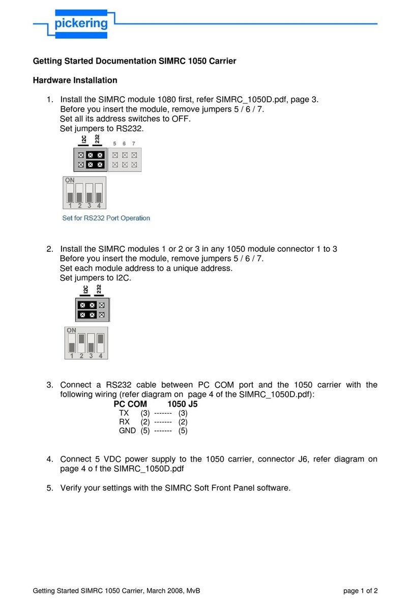
Agilent Technologies
Agilent 34921A-34925A
Low Frequency
Multiplexer Modules
User’s Guide
Agilent Technologies, Inc.
Printed in Malaysia
Edition 1
June 2008 E0608
*34980-90021*
34980-90021

Notices
© Agilent Technologies, Inc. 2008
No part of this manual may be reproduced
in any form or by any means (including
electronic storage and retrieval or transla-
tion into a foreign language) without prior
agreement and written consent from
Agilent Technologies, Inc. as governed
by United States and international copy-
right laws.
Manual Part Number
34980-90021
Edition
First Edition, June 2008
Printed in Malaysia
Agilent Technologies, Inc.
3501 Stevens Creek Blvd
Santa Clara, CA 95052 USA
Microsoft® and Windows® are U.S. regis-
tered trademarks of Microsoft Corporation.
Software Revision
This guide is valid for the firmware that
was installed in the instrument at the time
of manufacture. However, upgrading the
firmware may add or change product
features. For the latest firmware and
documentation, go to the product page at:
www.agilent.com/find/34980A
Warranty
The material contained in this docu-
ment is provided “as is,” and is sub-
ject to being changed, without notice,
in future editions. Further, to the max-
imum extent permitted by applicable
law, Agilent disclaims all warranties,
either express or implied, with regard
to this manual and any information
contained herein, including but not
limited to the implied warranties of
merchantability and fitness for a par-
ticular purpose. Agilent shall not be
liable for errors or for incidental or
consequential damages in connection
with the furnishing, use, or perfor-
mance of this document or of any
information contained herein. Should
Agilent and the user have a separate
written agreement with warranty
terms covering the material in this
document that conflict with these
terms, the warranty terms in the sep-
arate agreement shall control.
Technology Licenses
The hardware and/or software described in
this document are furnished under a
license and may be used or copied only in
accordance with the terms of such license.
Restricted Rights Legend
U.S. Government Restricted Rights.
Software and technical data rights granted
to the federal government include only
those rights customarily provided to end
user customers. Agilent provides this
customary commercial license in Software
and technical data pursuant to FAR 12.211
(Technical Data) and 12.212 (Computer
Software) and, for the Department of
Defense, DFARS 252.227-7015 (Technical
Data - Commercial Items) and DFARS
227.7202-3 (Rights in Commercial Com-
puter Software or Computer Software
Documentation).
Safety Notices
CAUTION
A CAUTION notice denotes a haz-
ard. It calls attention to an operat-
ing procedure, practice, or the like
that, if not correctly performed or
adhered to, could result in damage
to the product or loss of important
data. Do not proceed beyond a
CAUTION notice until the indicated
conditions are fully understood and
met.
WARNING
A WARNING notice denotes a
hazard. It calls attention to an
operating procedure, practice, or
the like that, if not correctly per-
formed or adhered to, could result
in personal injury or death. Do not
proceed beyond a WARNING
notice until the indicated condi-
tions are fully understood and met.
ii Agilent 34921A-34925A Low Frequency Multiplexer Modules User’s Guide

Additional Safety Notices
The following general safety precautions
must be observed during all phases of oper-
ation of this instrument. Failure to comply
with these precautions or with specific
warnings or instructions elsewhere in this
manual violates safety standards of design,
manufacture, and intended use of the
instrument. Agilent Technologies assumes
no liability of the customer’s failure to com-
ply with the requirements.
General
Do not use this products in any manner not
specified by the manufacturer. The protec-
tive features of this product may be
impaired if it is used in a manner not speci-
fied in the operation instructions.
Before Applying Power
Verify that all safety precautions are taken.
Make all connections to the unit before
applying power.
Ground the Instrument
This product is provided with protective
earth terminals. To minimize shock hazard,
the instrument must be connected to the
ac power mains through a grounded power
cable, with the ground wire firmly con-
nected to an electrical ground (safety
ground) at the power outlet. Any interrup-
tion of the protective (grounding) conduc-
tor or disconnection of the protective earth
terminal will cause a potential shock haz-
ard that could result in personal injury.
Do Not Operate in an Explosive
Atmosphere
Do not operate the instrument in the pres-
ence of flammable gases or fumes.
Do Not Remove the Instrument
Cover
Only qualified, service-trained personal
who are aware of the hazards involved
should remove instrument covers. Always
disconnect the power cable and any exter-
nal circuits before removing the instrument
cover.
Do Not Modify the Instrument
Do not install substitute parts or perform
any unauthorized modification to the prod-
uct. Return the product to an Agilent Sales
and Service Office for service and repair to
ensure that safety features are maintained.
In Case of Damage
Instruments that appear damaged or defec-
tive should be made inoperative and
secured against unintended operation until
they can be repaired by qualified service
personnel.
Safety Symbols
Waste Electrical and Electronic
Equipment (WEEE) Directive
2002/96/EC
This product complies with the WEEE
Directive (2002/96/EC) marking require-
ment. The affixed product label (see above)
indicates that you must not discard this
electrical/electronic product in domestic
household waste.
Product Category: With reference to the
equipment types in the WEEE directive
Annex 1, this product is classified as a
“Monitoring and Control instrumentation”
product.
To return unwanted products, contact
your local Agilent office, or go to
www.agilent.com/environment/product
for more information.
Technical Support
If you have questions about your shipment,
or if you need information about warranty,
service, or technical support, contact
Agilent Technologies:
In the United States: (800) 829-4444
In Europe: 31 20 547 2111
In Japan: 0120-421-345
Or go to www.agilent.com/find/assist
for information on contacting Agilent in
your country of specific location. You can
also contact your Agilent Technologies
Representative.
Alternating current
Frame or chassis
terminal
Standby supply. Unit is
not completely
disconnected from ac
mains when switch is off
Caution, risk of electric
shock
Caution, refer to
accompanying description
Agilent 34921A-34925A Low Frequency Multiplexer Modules User’s Guide iii

iv Agilent 34921A-34925A Low Frequency Multiplexer Modules User’s Guide
The Declaration of Conformity (DoC) for the 34980A mainframe
instrument can be found on page iii in the 34980A Mainframe User’s
Guide. That DoC applies to the 34980A mainframe and all available
plug- in modules.

Agilent 34921A-34925A Low Frequency Multiplexer Modules User’s Guide v
Contents
Low Frequency Multiplexer Modules . . . . . . . . . . . . . . . . . . . . . . . . . . . . . . . . . . . . . . . . . . . .1
Multiplexer Module Capabilities . . . . . . . . . . . . . . . . . . . . . . . . . . . . . . . . . . . . . . . . . . . . .1
Measurement Functions for the Multiplexer Modules . . . . . . . . . . . . . . . . . . . . . . . . . .2
Operating Considerations . . . . . . . . . . . . . . . . . . . . . . . . . . . . . . . . . . . . . . . . . . . . . . . . . . .3
SCPI Programming Examples for the Multiplexer Modules . . . . . . . . . . . . . . . . . . . . . . . . .4
34921A 40-Channel Armature Multiplexer with Low Thermal Offset . . . . . . . . . . . . . . . . .7
34921A Simplified Schematic. . . . . . . . . . . . . . . . . . . . . . . . . . . . . . . . . . . . . . . . . . . . . . . .9
34921A D-Sub Connectors . . . . . . . . . . . . . . . . . . . . . . . . . . . . . . . . . . . . . . . . . . . . . . . . .10
34921T Terminal Block . . . . . . . . . . . . . . . . . . . . . . . . . . . . . . . . . . . . . . . . . . . . . . . . . . . .11
34922A 70-Channel Armature Multiplexer. . . . . . . . . . . . . . . . . . . . . . . . . . . . . . . . . . . . . . .13
34922A Simplified Schematic. . . . . . . . . . . . . . . . . . . . . . . . . . . . . . . . . . . . . . . . . . . . . . .14
34922A D-Sub Connectors . . . . . . . . . . . . . . . . . . . . . . . . . . . . . . . . . . . . . . . . . . . . . . . . .15
34922T Terminal Blocks . . . . . . . . . . . . . . . . . . . . . . . . . . . . . . . . . . . . . . . . . . . . . . . . . . .17
34923A 40/80-Channel Reed Multiplexer . . . . . . . . . . . . . . . . . . . . . . . . . . . . . . . . . . . . . . .19
Two-Wire Mode . . . . . . . . . . . . . . . . . . . . . . . . . . . . . . . . . . . . . . . . . . . . . . . . . . . . . . . . . .20
Four-Wire Mode . . . . . . . . . . . . . . . . . . . . . . . . . . . . . . . . . . . . . . . . . . . . . . . . . . . . . . . . . .20
One-Wire Mode . . . . . . . . . . . . . . . . . . . . . . . . . . . . . . . . . . . . . . . . . . . . . . . . . . . . . . . . . .20
34923A Simplified Schematic for Two- or Four-Wire Mode. . . . . . . . . . . . . . . . . . . . . .21
34923A D-Sub Connectors for Two- or Four-Wire Mode . . . . . . . . . . . . . . . . . . . . . . . .22
34923T-001 Terminal Block for Two-Wire or Four-Wire Mode . . . . . . . . . . . . . . . . . . .23
34923A Simplified Schematic for One-Wire Mode . . . . . . . . . . . . . . . . . . . . . . . . . . . . .24
34923A D-Sub Connectors for One-Wire Mode. . . . . . . . . . . . . . . . . . . . . . . . . . . . . . . .25
34923T-002 Terminal Block for One-Wire Mode . . . . . . . . . . . . . . . . . . . . . . . . . . . . . . .26
34924A 70-Channel Reed Multiplexer. . . . . . . . . . . . . . . . . . . . . . . . . . . . . . . . . . . . . . . . . . .27
34924A Simplified Schematic. . . . . . . . . . . . . . . . . . . . . . . . . . . . . . . . . . . . . . . . . . . . . . .29
34924A D-Sub Connectors . . . . . . . . . . . . . . . . . . . . . . . . . . . . . . . . . . . . . . . . . . . . . . . . .30
34924T Terminal Blocks . . . . . . . . . . . . . . . . . . . . . . . . . . . . . . . . . . . . . . . . . . . . . . . . . . .32
34925A 40/80-Channel Optically-Isolated FET Multiplexer . . . . . . . . . . . . . . . . . . . . . . . .34
Two-Wire Mode . . . . . . . . . . . . . . . . . . . . . . . . . . . . . . . . . . . . . . . . . . . . . . . . . . . . . . . . . .34
Four-Wire Mode . . . . . . . . . . . . . . . . . . . . . . . . . . . . . . . . . . . . . . . . . . . . . . . . . . . . . . . . . .34
One-Wire Mode . . . . . . . . . . . . . . . . . . . . . . . . . . . . . . . . . . . . . . . . . . . . . . . . . . . . . . . . . .35
Interlock Protection . . . . . . . . . . . . . . . . . . . . . . . . . . . . . . . . . . . . . . . . . . . . . . . . . . . . . . .35
Overvoltage Protection . . . . . . . . . . . . . . . . . . . . . . . . . . . . . . . . . . . . . . . . . . . . . . . . . . . .35
34925A Simplified Schematic for Two- or Four-Wire Mode. . . . . . . . . . . . . . . . . . . . . .36
34925A D-Sub Connectors for Two- or Four-Wire Mode . . . . . . . . . . . . . . . . . . . . . . . .37
34925T-001 Terminal Block for Two-Wire or Four-Wire Mode . . . . . . . . . . . . . . . . . . .38
34925A Simplified Schematic for One-Wire Mode . . . . . . . . . . . . . . . . . . . . . . . . . . . . .39
34925A D-Sub Connectors for One-Wired Mode . . . . . . . . . . . . . . . . . . . . . . . . . . . . . .40
34925T-002 Terminal Block for One-Wire Mode . . . . . . . . . . . . . . . . . . . . . . . . . . . . . . .41
Index

vi Agilent 34921A-34925A Low Frequency Multiplexer Modules User’s Guide
Low Frequency Multiplexer Modules
Agilent 34921A-34925A Low Frequency Multiplexer Modules User’s Guide 1
Low Frequency Multiplexer Modules
This User’s Guide covers the following five plug-in modules for the Agilent
34980A Multifunction Switch/Measure Unit:
Multiplexer Module Capabilities
Each multiplexer (MUX) module features two banks of channels, providing
broad multiplexing and measurement capabilities. Briefly:
•You can connect a MUX to an external instrument, and/or switch
multiple analog signals to the internal DMM.
•With the 34921A, 34922A, 34923A, and the 34924A modules, you can
close more than one channel in each bank simultaneously (N:1
configuration).
•Since the 34925A module is protected with overvoltage circuitry, you
can close only one channel in each bank at one time (1:N
configuration).
•You can connect multiple MUXes to the built- in Analog Buses, which
allow you to scan as many as 560 2-wire (differential) channels or 640
1- wire (single- ended) channels in one 34980A mainframe.
34921A 40-channel armature multiplexer w/low thermal offset
34922A 70-channel armature multiplexer
34923A 40/80-channel reed multiplexer
34924A 70-channel reed multiplexer
34925A 40-channel optically isolated FET multiplexer

2 Agilent 34921A-34925A Low Frequency Multiplexer Modules User’s Guide
Low Frequency Multiplexer Modules
Measurement Functions for the Multiplexer Modules
The MUX modules support the DMM measurement functions shown in the
following table.
Measurement Function(s)
34921A
4 0 - c h
Armature
M u x
34922A
7 0 - c h
Armature
M u x
3 4 9 2 3 A
4 0 - c h
R e e d M u x
( 2 -W i r e )
3 4 9 2 3 A
80-ch
R e e d M u x
( 1 -W i r e )
34924A
7 0 - c h
R e e d M u x )
34925A
40-ch
F E T M u x
( 2 -W i r e )
34925A
80-ch
F E T M u x
( 1 -W i r e )
Voltage, AC/DC Yes Yes Yes Yes Yes Yes Yes
Current, AC/DC Yes1No No No No No No
Frequency/Period Yes Yes Yes Yes Yes Yes Yes
Ohms 2-Wire Yes Yes Yes5Yes5Yes5Yes6Yes6
Ohms 4-Wire Yes Yes Yes5No Yes5Yes6No
Thermocouple Yes2Yes3Yes3,4 Yes3,4 Yes3,4 Yes3Yes3
RTD 2-Wire Yes Yes Yes5Yes5Yes5No No
RTD 4-Wire Yes Yes Yes5No Yes5Yes6No
Thermistor Yes Yes Yes5Yes5Yes5No No
1Direct current measurements are allowed on channels 41 through 44 only (for all other channels, external shunts are required).
2Optional 34921T Terminal Block is required for thermocouple measurements with built-in internal reference junction.
3A fixed or external reference junction temperature is required for thermocouple measurement with this module.
4Impact of higher offset voltage specification (< 50 µV) must be taken into consideration.
51 kΩor higher range used unless 100Ωseries resistors are bypassed on module.
610 kΩor higher range used for loads over approximately 300Ωdue to series resistance of FET channels.

Low Frequency Multiplexer Modules
Agilent 34921A-34925A Low Frequency Multiplexer Modules User’s Guide 3
Operating Considerations
Current Ratings
See the Introduction to the Plug In Modules chapter of the 34980A
Mainframe User’s Guide for detailed environmental operating conditions
for the 34980A mainframe and its installed modules. That guidance sets
maximum per channel current ratings at rated voltage for pollution degree
1 (dry) and pollution degree 2 (possible condensation) conditions, for all
of the multiplexer modules.
Safety Interlock
The Analog Buses of the 34980A are capable of carrying 300V signals. The
MUX modules have a hardware Safety Interlock feature that automatically
opens the Analog Bus relays when the associated interlock pins on the
D- sub connectors (faceplate) lose continuity. This prevents signals on the
Analog Buses from being present on the D- sub connector pins. Optional
terminal blocks available from Agilent automatically provide continuity for
these interlock pins. If cables are used, you must provide continuity for
the interlock pins in your DUT assembly. See the pinout information later
in this guide for the location of interlock pins on each module.
The MUX modules have Analog Bus relays on each of their two banks.
Therefore, the interlock pins are present on both the Bank 1 and Bank 2
D- sub connectors on the MUX modules.
Normally, if you attempt to connect to the Analog Buses without a
terminal block or cable connected, an error is generated. The
SYSTem:ABUS:INTerlock:SIMulate command allows you to temporarily
disable errors generated by the Safety Interlock feature and enables the
simulation mode. Although Safety Interlock errors are suppressed in this
mode, the actual Analog Bus relays affected by the Safety Interlock are
disabled as long as no terminal block or cable is connected to the module.
•The simulation mode applies to the entire mainframe and cannot be
selectively used on individual modules.
•When the simulation mode is enabled, the Analog Bus relays will
appear to close and open as directed. For example, no errors are
generated if you close an Analog Bus relay from the front panel, remote
interface, or Web Interface. However, remember that the Safety Interlock
feature prevents the actual hardware state of the Analog Bus relays
from being changed. When you connect a terminal block or cable to the
module, the Analog Bus relays will be closed.
•The simulation setting is stored in volatile memory and will be lost
when power is turned off. To re-enable the simulation mode after
power has been off, you must send the command again.
CAUTION The Safety Interlock feature is implemented in hardware on the modules
and cannot be circumvented. Regardless of whether the simulation mode
is enabled or disabled, all Analog Bus connections are prohibited as long
as no terminal block or properly-wired cable is connected to the module.

4 Agilent 34921A-34925A Low Frequency Multiplexer Modules User’s Guide
SCPI Programming Examples for the Multiplexer Modules
The programming examples below provide you with SCPI command
examples to use for actions specific to the MUX modules.
The slot and channel addressing scheme used in these examples follow the
form sccc where sis the mainframe slot number (1 through 8) and ccc is
the three- digit channel number. For information on specific MUX channel
configurations, refer to the simplified schematics contained in each MUX
section of this manual.
For complete information on the SCPI commands used to program the
34980A, with example programs, refer to the Agilent 34980A
Programmer’s Reference contained on the 34980A Product Reference CD.
Opening and Closing Channels
Example: Closing and opening channels on the armature and reed MUX modules
This command closes the specified channels on a MUX module. If any
channel in a bank is defined to be part of the scan list, and a scan is
occurring, attempting to close another channel (including Analog Bus
channels) within the same bank will result in an error. Channel closures
in the other bank are allowed as long as no channels are part of the scan
list.
The following commands close and open channels 13 and 15 through 18 in
slot 3.
ROUTe:CLOSe (@3013,3015:3018)
ROUTe:OPEN (@3013,3015:3018)
Example: Closing channels on the FET MUX module The FET MUX module
supports a 1:Ntype closure, meaning that you can have only one channel
per bank closed at a time. The following command closes then
automatically opens each channel from 1-19 (Bank 1) in succession,
leaving channel 20 closed. Then the command continues closing and
opening channels 21 to 39 (Bank 2), then leaving channel 40 closed.
At the end, only channels 20 and 40 will be closed, while all other
channels will have been closed and then opened. In this process,
a channel will open before the next channel in succession closes, making
this a “break- before- make” series.
ROUTe:CLOSe (@3001:3040)
The following command opens the closed channel on Bank 1 of a FET
MUX module in slot 3, and closes channel 15 on that bank.
ROUTe:CLOSe (@3015)

SCPI Programming Examples for the Multiplexer Modules
Agilent 34921A-34925A Low Frequency Multiplexer Modules User’s Guide 5
Example: Closing and opening Analog Bus relays The following command
connects the Analog Buses to Bank 1 (via the Analog Bus relays on Bank
1) for a module in slot 3.
ROUTe:CLOSe (@3911,3912,3913,3914)
ROUTe:OPEN (@3911,3912,3913,3914)
The Analog Bus relays (numbered s911, s912, s913, etc.) on the MUX
modules are ignored if they are included in a range of channels.
An error will be generated if an Analog Bus relay is specified as the
first or last channel in a range of channels. For example, the following
command closes all valid channels between channel 30 (slot 1) and
channel 5 (slot 2). In addition, this command closes Analog Bus relay 911
on the module in slot 1 (Bank 1). Note that although the specified range
of channels includes the other Analog Bus relays, they are ignored and are
not closed by this command.
ROUTe:CLOSe (@1030:2005,1911)
Example: Querying channels for open or close state The following command
returns a 1 (true) or 0 (false) state of channel 036 for a module in slot 3.
ROUTe:CLOSe (@3036)
ROUTe:CLOSe? (@3036) !Returns a 1
ROUTe:OPEN? (@3036) !Returns a 0
Making Measurements
Example: Making voltage measurements The following command configures
channels 9 and 10 in slot 4 for DC voltage measurements, triggers the
internal DMM to scan channels 9 and 10, and returns the reading.
The 1 V range is selected with 1 mV resolution.
MEASure:VOLTage:DC? 1,0.001, (@4009,4010)
Example: Making voltage measurements using INITiate and FETCh?
The following program segment shows how to use the INITiate command
with the CONFigure and FETCh? commands. The ROUTe:SCAN command
puts channels 3 and 8 (of a module in slot 1) into the scan list (and
redefines the scan list). The INITiate command scans the specified
channels, and then sends the readings to memory. The FETCh? command
transfers the readings from memory to the user.
CONFigure:VOLTage:DC 10,0.003,(@1003,1008)
ROUTe:SCAN (@1003,1008)
INITiate
FETCh?
Example: Making current measurements The following command configures
channel 43 for a 34921A modules in slot 7 for dc current measurements,
triggers the internal DMM to scan the channel, and then sends the reading
to the output buffer of the 34980A. The default settings for range
(autorange) and resolution (1 PLC) are used for the measurement.
MEASure:CURRent:DC? (@7043)

6 Agilent 34921A-34925A Low Frequency Multiplexer Modules User’s Guide
SCPI Programming Examples for the Multiplexer Modules
Configuring a Module
Example: Configuring a module for 2-wire or 1-wire mode The following
command configures a MUX module in slot 4 for 1-wire mode. Because
you can configure only the 34923A and 34925A MUX modules (and the
34933A matrix module) for either 2- wire or 1- wire mode, an error is
generated if you send this command to a slot that does not contain
one of those three modules. If you are using terminal blocks with
these modules, be sure to use the corresponding 2- wire or 1- wire terminal
block.
SYSTem:MODule:WIRE:MODE WIRE1,4
Example: Querying the system for module Identify The following command
returns the identity of the module installed in slot 7.
SYSTem:CTYPe? 7
Querying and Clearing Cycle Count, and Resetting Modules
Example: Querying the cycle count for a relay The following command returns
the cycle count on channel 7 and channel 16 for a MUX module in slot 1.
DIAGnostic:RELay:CYCLes? (@1007,1016)
Example: Clearing the cycle count for a relay The following command resets
the cycle count to zero on the channels 7 and 16 for a MUX module in
slot 1.
DIAGnostic:RELay:CYCLes:CLEar (@1007,1016)
Example: Resetting module(s) to power-on state The following command
resets a module in slot 4 to its power- on state.
SYSTem:CPON 4
NOTE When using a command to configure the system, the new
configuration does not take effect until you cycle power on the
34980A.
NOTE For the 34923A and the 34925A MUX modules, the query response
may include a suffix to indicate a 1-wire configuration. For example,
the response for the 34923A will be either "34923A" (differential
mode) or "34923A-1W" (single-ended mode).
NOTE The 34925A will return 0 for relay counts because the FET relays on
that module are non-mechanical and have an undefined lifetime.

34921A 40-Channel Armature Multiplexer with Low Thermal Offset
Agilent 34921A-34925A Low Frequency Multiplexer Modules User’s Guide 7
34921A 40-Channel Armature Multiplexer with Low Thermal Offset
The 34921A 40- Channel Armature Multiplexer (40-Ch Arm MUX) is
divided into two banks with 20 latching armature switches (channels 1- 20
and 21- 40) in each. This module also offers four additional fused relays
(channels 41- 44) for making AC and DC current measurements with the
internal DMM with no external shunts needed. These current channels
feature “make- before- break” connections to ensure continuous current flow
when switching from one current channel to another. The current fuses
are replaceable. Refer to the 34980A Service Guide for specific
information about these fuses.
This module also contains nine armature Analog Bus relays (channels
911- 914, 921- 924, and 931), four on each bank that can connect the bank
relays to the system Analog Buses and one that connects the current
relays to the current input of the DMM. Through ABus1 and ABus2 you
can connect any of the channels to the internal DMM for voltage or
resistance measurements. Refer to the simplified schematic on page 9.
Using program commands or the mainframe front panel, you can control
each of the channel switches individually, and thus configure the 34921A
module in these modes:
•two independent 20- channel 2- wire MUXes. This configuration requires
neither using external wiring nor connecting through the internal
Analog Buses.
•one 20- channel 4- wire MUX. This configuration requires neither using
external wiring nor connecting through the internal Analog Buses.
For 4- wire resistance measurements, the instrument automatically pairs
channel n on Bank 1 (source) with channel n+20 on Bank 2 (sense) to
provide these connections. Four- wire controls occur only when doing
4- wire measurement operations through the internal DMM, such as
MEASure:FRESistance? or scanning a channel previously configured
as 4- wire.
•one 40- channel 2- wire MUX. You must use external wiring or connect
through the internal Analog Bus relays for this configuration. For
example, closing Analog Bus channels 913 and 923 connects Bank 1 and
Bank 2 through ABus3. Or, externally you can connect COM1 to COM2
to create this configuration.
NOTE ABus1 consists of three wires that are used for current and voltage
measurements. A separate current bus on ABus1 connects to the
internal DMM current measurement input and this bus can be
connected only to channels 41 through 44. The current channel low
(L) signal path is common with the ABus1 low (L) signal path.
You cannot measure current and voltage on ABus1 simultaneously.

8 Agilent 34921A-34925A Low Frequency Multiplexer Modules User’s Guide
34921A 40-Channel Armature Multiplexer with Low Thermal Offset
Low thermal offset voltage makes the 34921A ideal for low-level signal
switching. The 34921T optional terminal block provides a built-in
thermocouple reference junction that helps minimize errors due to thermal
offset when you measure thermocouples.
This module has capability to scan as many as 100 channels/second using
the internal DMM. With the automatic “break- before-make” connection
operation, you are assured that no two signals are connected to each other
during a scan. When using the module in a non-scanning mode, you can
close as many channels as you wish.
This module is safety interlock protected, which means whenever the
D- sub connector end of the modules is exposed, the Analog Bus relays
automatically open and disconnect from the Analog Bus. For more
information, see “Safety Interlock” on page 3 and “34921A D- Sub
Connectors” on page 10.
When power is off, all channel relays maintain state, and the Analog Bus
relays open.

34921A 40-Channel Armature Multiplexer with Low Thermal Offset
Agilent 34921A-34925A Low Frequency Multiplexer Modules User’s Guide 9
34921A Simplified Schematic
This drawing shows two independent 20- channel 2- wire MUXes.
026
027
028
029
030
ABus2
DMM
(SENS) ABus3 ABus4
931
923
913 914
924
922
912911
921
DMM
(MEAS)
L
001
002
003
004
005
H
L006
007
008
009
010
H
L011
012
013
014
015
L
H016
017
018
019
020
021
022
023
024
025 HL
031
032
033
034
035
036
037
038
039
040 L
HLHL
Current
Fuse
Fuse
Fuse
Fuse
042
043
041 LH
LH
LH
LH
LH
LHLH
LH
H
L
L
L
L
L
044
LH
H
LH
COM 2
Bank 2
Current
Bank 1
COM 1
Analog Buses
I
I
I
I
IABus1
NOTE: The three-digit number assigned to each switch represents the channel number.
NOTE:
Bank Relays: Armature latching
Analog Bus Relays: Armature non-latching

10 Agilent 34921A-34925A Low Frequency Multiplexer Modules User’s Guide
34921A 40-Channel Armature Multiplexer with Low Thermal Offset
34921A D-Sub Connectors
Bank 1
Bank 2
For orientation, the D-sub connector
end of the module is facing you.
Bank 2
Bank 1
17L
34 35 36 37 38 39 40 41 42 43 44 45 46 47 48 49 50
18 19 20 21 22 23 24 25 26 27 28 29 30 31 32 33
1 2 3 4 5 6 7 8 9 10 11 12 13 14 15 16 17
TSIL* 11H 11L 7H 7L 17H 13H 13L 9H 9L 19H 19L 15H 15L Interlock 1
Interlock11H 1L 2H 2L 3H 3L COM
1H COM
1L 4H 4L 14H 14L 5H 5L 20H 20L
18HGND 6H 6L 16H 16L 12H 12L 8H 8L 18L 10H 10L AMP
41L AMP
41IAMP
42L AMP
42I
*TSIL = Temperature Sensor
Interface Line. Provides
thermocouple reference
sensor serial output line to
the mainframe processor.
50-Pin D-Sub
Male Connector
Description Pin Description Pin Description Pin Description Pin Description Pin
1H 1 6H 35 11H 19 16H 37 COM1 H 7
1L 2 6L 36 11L 20 16L 38 COM1 L 8
2H 3 7H 21 12H 39 17H 23 Interlock 1 17
2L 4 7L 22 12L 40 17L 24 Interlock 1 33
3H 5 8H 41 13H 25 18H 43 GND 34
3L 6 8L 42 13L 26 18L 44 TSIL* 18
4H 9 9H 27 14H 11 19H 29 AMP 41L 47
4L 10 9L 28 14L 12 19L 30 AMP 41I48
5H 13 10H 45 15H 31 20H 15 AMP 42L 49
5L 14 10L 46 15L 32 20L 16 AMP 42I50
WARNING:: As a safety
feature, interlock 1 pins
(17 and 33) on Bank 1
must be shorted to
enable the Bank 1 Analog
Bus relays to close. The
optional 34921T terminal
block shorts these pins
for you. This feature
protects inadvertent
routing of high voltages
from the Analog Bus to
the D-sub connector of
the module.
WARNING
34 35 36 37 38 39 40 41 42 43 44 45 46 47 48 49 50
23L Interlock 221H 21L 22H 22L 23H COM
2H COM
2L 24H 24L 34H 34L 25H 25L 40H 40L
1234567891011121314151617
37LTSIL* 31H 31L 27H 27L 37H 33H 33L 29H 29L 39H 39L 35H 35L Interlock 2
18 19 20 21 22 23 24 25 26 27 28 29 30 31 32 33
GND 26H 26L 36H 36L 32H 32L 28H 28L 38H 38L 30H 30L AMP
43L AMP
43IAMP
44L AMP
44I
50-Pin D-Sub
Male Connector
*TSIL = Temperature Sensor
Interface Line. Provides
thermocouple reference
sensor serial output line to
the mainframe processor.
Description Pin Description Pin Description Pin Description Pin Description Pin
21H 1 26H 35 31H 19 36H 37 COM2 H 7
21L 2 26L 36 31L 20 36L 38 COM2 L 8
22H 3 27H 21 32H 39 37H 23 Interlock 2 17
22L 4 27L 22 32L 40 37L 24 Interlock 2 33
23H 5 28H 41 33H 25 38H 43 GND 34
23L 6 28L 42 33L 26 38L 44 TSIL* 18
24H 9 29H 27 34H 11 39H 29 AMP 43L 47
24L 10 29L 28 34L 12 39L 30 AMP 43I48
25H 13 30H 45 35H 31 40H 15 AMP 44L 49
25L 14 30L 46 35L 32 40L 16 AMP 44I50
WARNING:: As a safety
feature, interlock 2 pins
(17 and 33) on Bank 2
must be shorted to
enable the Bank 2 Analog
Bus relays to close. The
optional 34921T terminal
block shorts these pins
for you. This feature
protects inadvertent
routing of high voltages
from the Analog Bus to
the D-sub connector of
the module.
WARNING

34921A 40-Channel Armature Multiplexer with Low Thermal Offset
Agilent 34921A-34925A Low Frequency Multiplexer Modules User’s Guide 11
34921T Terminal Block
This terminal block with screw- type connections is labeled with the model
number and the abbreviated module name. In addition, space is available
on the label for you to write the slot number.
The 34921T is the only terminal block that provides an isothermal
block with temperature reference for thermocouple measurements.
The temperature sensor is located on the bottom side of the PC board
as shown below. Also shown are two holes that you can use for connecting
an external temperature reference to the terminal block.
NOTE All modules that connect to the internal DMM are interlock
protected. This means that when an installed module is exposed
(no terminal block or cable is connected), the Analog Bus relays are
open and disconnected from the Analog Buses. See “Safety
Interlock” on page 3 for further information.
Temperature
Sensor
34921T (viewed from bottom side)
External
Reference
CAUTION When wiring the terminal block via cables to the mainframe, make
sure the cables are connected to the correct connector. The cables
provide communication and power to the temperature sensor on
the 34921T terminal block. If cabling is not correct, an error may
occur indicating that the 34921A module is not fully operational.

12 Agilent 34921A-34925A Low Frequency Multiplexer Modules User’s Guide
34921A 40-Channel Armature Multiplexer with Low Thermal Offset
The 34980A Product Reference CD (shipped with the instrument) contains
a 34921T Wiring Log for you to document your wiring configuration for
this module. You can open the wiring log file in Microsoft® Excel® or
Adobe® Acrobat® format.
WireSize:
20AWGTypical
18AWGMax

34922A 70-Channel Armature Multiplexer
Agilent 34921A-34925A Low Frequency Multiplexer Modules User’s Guide 13
34922A 70-Channel Armature Multiplexer
The high- density 34922A 70- Channel Armature Multiplexer (70- Ch Arm
MUX) is divided into two banks with 35 latching armature switches
(channels 1- 35 and 36- 70) in each. This module also contains eight
armature Analog Bus relays (channels 911-914 and 921- 924), four on each
bank that can connect the bank relays to the system Analog Buses.
Through ABus1 and ABus2 you can connect any of the channels to the
internal DMM for voltage or resistance measurements. Refer to the
simplified schematic on page 14.
Using program commands or the mainframe front panel, you can control
each of the channel switches individually, and thus configure the 34922A
in these modes:
•two independent 35- channel 2- wire MUXes. This configuration requires
neither using external wiring nor connecting through the internal
Analog Buses.
•one 35- channel 4- wire MUX. This configuration requires neither using
external wiring nor connecting through the internal Analog Buses.
For 4- wire resistance measurements, the instrument automatically pairs
channel n on Bank 1 (source) with channel n+35 on Bank 2 (sense) to
provide these connections. Four- wire controls occur only when doing
4- wire measurement operations through the internal DMM, such as
MEASure:FRESistance? or scanning a channel previously configured
as 4- wire.
•one 70- channel 2- wire MUX. You must use external wiring or connect
through the internal Analog Bus relays for this configuration.
For example, closing Analog Bus channels 913 and 923 connects
Bank 1 and Bank 2 through ABus3. Or, externally you can connect
COM1 to COM2 to create this configuration.
This module has capability to scan as many as 100 channels/second using
the internal DMM. With the automatic “break- before-make” connection
operation, you are assured that no two signals are connected to each other
during a scan. When using the module in a non-scanning mode, you can
close as many channels as you wish.
This module is interlock protected, which means whenever the D- sub
connector end of the modules is exposed, the Analog Bus relays
automatically open and disconnect from the Analog Bus. For more
information, see “Safety Interlock” on page 3 and “34922A D- Sub
Connectors” on page 15.
When the power is off, all channel relays maintain state, and the Analog
Bus relays open.

14 Agilent 34921A-34925A Low Frequency Multiplexer Modules User’s Guide
34922A 70-Channel Armature Multiplexer
34922A Simplified Schematic
This drawing shows two independent 35- channel 2- wire MUXes.
LH
ABus2
DMM
(SENS) ABus3 ABus4
ABus1
DMM
(MEAS)
001
002
003
004
005
H
L
006
007
HL
H
015
016
017
018
019
L
020
021
022
023
024
025
026
H
L
027
028
029
030
031
032
033
H
L
034
035
008
009
010
011
012
H
L
013
014
036
037
038
039
040
041
042 HL
043
044
045
046
047
048
049 HLHL
050
051
052
053
054
055
056
057
058
059
060
061
062
063 HL
064
065
066
067
068
069
070 HL
911
924
914913
923
912
921 922
LH
LHLHLHLH
LHLH
HL
Bank 1
Bank 2
COM 1
COM 2
Analog Buses
NOTE: The three-digit number
assigned to each switch represents
the channel number.
NOTE:
Bank Relays: Armature latching
Analog Bus Relays: Armature non-latching
This manual suits for next models
1
Table of contents
Other Agilent Technologies Multiplexer manuals

Agilent Technologies
Agilent Technologies 34941A User manual

Agilent Technologies
Agilent Technologies E1470A Series User manual

Agilent Technologies
Agilent Technologies VXI bus E1476A User manual

Agilent Technologies
Agilent Technologies E1346A User manual

Agilent Technologies
Agilent Technologies Agilent E1345A User manual

Agilent Technologies
Agilent Technologies E8462A User manual

Agilent Technologies
Agilent Technologies VXI E1472A User manual

Agilent Technologies
Agilent Technologies E1343A Operating instructions

Agilent Technologies
Agilent Technologies 75000 Series User manual

Agilent Technologies
Agilent Technologies E1472A User manual