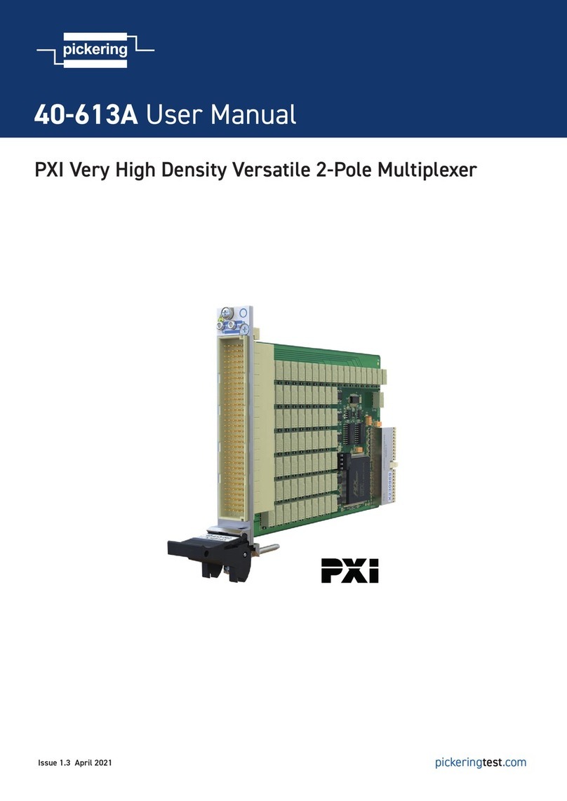
Page 1.2 30A SOLID STATE MULTIPLEXER MODULES 40-667C
pickering
SECTION 1 - TECHNICAL SPECIFICATION
PXI & CompactPCI Compliance
The module is compliant with the PXI Specification 2.2. Local
Bus, Trigger Bus & Star Trigger are not implemented.
Uses a 33 MHz 32-bit backplane interface.
Safety & CE Compliance
All modules are fully CE compliant and meet applicable
EU directives: Low-voltage safety EN61010-1:2010,
EMC Immunity EN61326-1:2013,
Emissions EN55011:2009+A1:2010.
Mechanical Characteristics
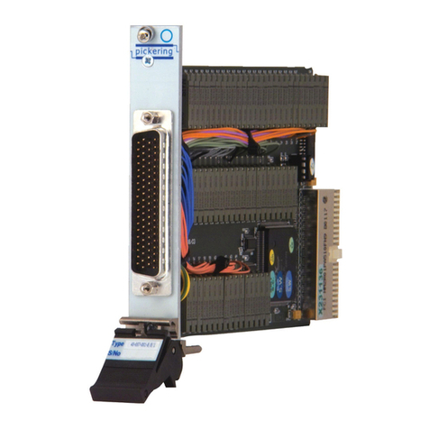
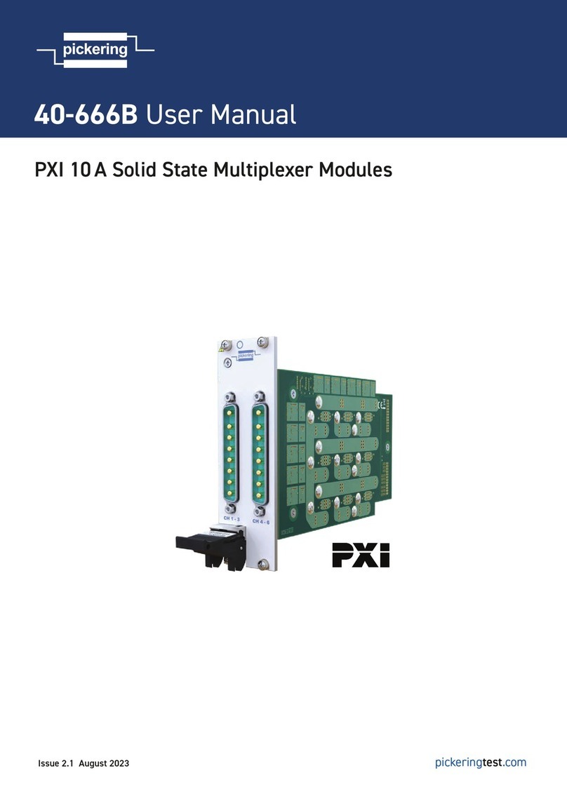
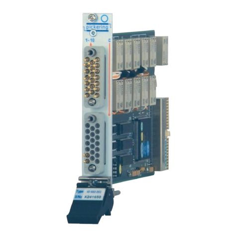
Double slot 3U PXI (CompactPCI card).
3D models for all versions in a variety of popular file formats
are available on request.
Connectors
PXI bus via 32-bit P1/J1 backplane connector.
Signals via 2 front panel 8-pin male power D-Type connectors,
for pin outs please refer to the operating manual.
Interlock via 4-pin female 00 series connector*
(40-667C versions with hardware interlock option)
*Mating half supplied when hardware interlock option
ordered, to be wired by end user.
Hardware Interlock
The 40-667C modules are available with an optional
hardware interlock. The interlock, when activated,
will return all relays to their default unpowered state
(assuming the relays are fully functional) and also
provide error notification via the software interface.
The interlock feature can be daisy-chained between
additional hardware interlock enabled modules for
example to allow one signal to disable multiple cards.
For further details please refer to the Hardware
Interlock section within the user manual.
100 Ω
+3.3 V
GND
External
Wire Link
Front Panel
Connector
Interlock
Daisy-chain
Interlock
Detection
Circiuitry
Processor Relay Driver(s)
SPI Serial
Comms
Output Enable
SPI Serial
Comms
Output Enable
Drive
Outputs
To
Relays
Interlock Signal Routing Diagram for 40-667C
Versions With Hardware Interlock Option
Interlock Connector
Switching Specification
Switch Type: Solid State MOSFET
Max Switch Voltage:
Continuous Switch Current:
Peak Current:
±40 V* (DC or AC peak)†
30 A continuous,
40 A continuous with single
relay per module closed
120 A for 200 µs
Max Common Current: 40 A
Path Resistance - On:
Leakage Current (at ±40 V):
6 mΩ at 25 ˚C typical
<1 µA at 25 ˚C and switch
cold, <5mA at max
temperature immediately
after switch has carried
maximum current for
>10 minutes.
Rise/Fall Time:
Operate Time:
Max Operating Speed at
nominal load:
40 µs/140 µs (typical)
250 µs
60 operations/sec
Expected Life (operations): Indefinite when used within
ratings
* For full voltage rating, signal sources to be switched
must be fully isolated from mains supply and safety earth.
† Differential voltage between channels must not exceed
rated voltage, additional caution should be used when
applying AC voltages as multiple asynchronous supplies
can create high differential voltages between channels.
Power Requirements
+3.3 V +5 V +12 V -12 V
100 mA 350 mA 0 0
40-667C
pickeringtest.com Page 2
Specifications
