Steren CCTV-908 User manual


ENGLISH
ENGLISH-02
IMPORTANT
Before using your new CCTV multiplexer for 8 cameras, please
read this instruction manual carefully. After reading it, please keep
this instruction manual for future references.
This device must be placed in an area with adequate ventilation.
Do not expose this device to direct sunlight, dust, or humidity.
Always use a clean dry cloth in order to clean this device.
If the power cord is damages, it must be replaced. See the
manufacturer, a service agent, or qualied personnel in order to.
FEATURES
Color system.
Connect up to 8 cameras.
Remote control.
Alarm port.
Recording system output.
•
•
•
•
•
•
•
•
•

ENGLISH
ENGLISH-03
CONTROLS
FRON PANEL
1.- Power indicator light.
Illuminates when the device is in use.
2.- IR sensor.
Receives the infrared signal from the remote control.
3.- Menu / A-B
Menu: Access for the setup menu and Exits setup mode
Change page A (cameras 1 to 4) or B (camera 5 to 8)
4.- Auto / Freeze.
Allows you to access the automatic sequence mode and freezes the
image.
5.- Zoom/Mode
Zoom funtion and Change display mode
1
2
345678910

ENGLISH
ENGLISH-04
6.- VCR / Enter.
VCR allows you to access the VCR. Enter applies the changes that
have been made in the setup menu.
7.- CAM1 and 5 / Up.
Allows you to select the camera connected to the channel 1 or 5 input
jack. Arrow key allows you to navigate in the setup menu.
8.- CAM2 and 6 / Down.
Allows you to select the camera connected to the channel 2 or 6 input
jack. Arrow key allows you to navigate in the setup menu.
9.- CAM3 and 7 / Left.
Allows you to select the camera connected to the channel 3 or 7 input
jack. Arrow key allows you to navigate in the setup menu.
10.- CAM4 and 8 / Right.
Allows you to select the camera connected to the channel 4 or 8 input
jack. Arrow key allows you to navigate in the setup menu.

ENGLISH
ENGLISH-05
REAR PANEL
1.- CAM Input.
Allows you to connect up to four cameras with BNC plugs.
2.- VCR input
Accept 1 composite video input for playback from the VCR.
3.- VCR output
Provide 1 composite video output for recording in the VCR.
4.- Monitor Output.
Allows you to connect a monitor through a BNC plug.
5.- ALARM
Accept alarm inputs and relay out. Refer to the alarm interface section.
6.- RS-232C connection
Provide RS-232C interface to be controlled by host
7.- Power Input. Allows you to connect the included power adaptor.
12345
6
7
ENGLISH
ENGLISH-06
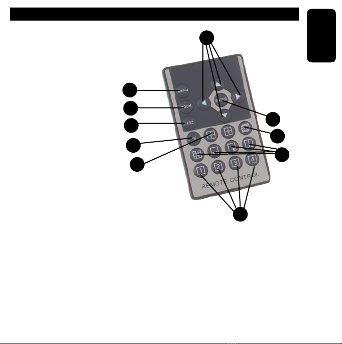
REMOTE CONTROL
1.- Menu
Enters or exits the main menu
2.- Zoom
Allows you to zoom in/out
on an image
3.- FRZ
Allows you to freeze the
image
4.- Arrow keys
Allows you to navigate
within a menu
5.- Enter
Allows you to select an option
within the menus
6.- A or B
A: Change page A (camera 1 to 4)
B: Change page B (camera 5 to 8)
7.- AUTO
Allows you to run the automatic sequence function
8.-Muti channel display.
Allows you to view the screen in different styles
1
2
3
4
5
6
7
8
9
10

ENGLISH
ENGLISH-07
9.- CAM1, 2, 3 y 4
Allows you to view CAM 1 and 5, CAM 2 and 6, CAM 3 and 7, CAM 4
and 8
10.- PB
Access to the record / playback VCR
CONNECTIONS
1. Locate the BNC inputs on the rear panel of the recorder
2. Connect camera 1 to the input jack labeled as “CAM1”. Do the same
for cameras 2, 3, 4, 6, 7 and 8.
3. Connect a monitor in the jack labeled as “MONITOR OUTPUT” with
a BNC connector
4. If you wish to use a VCR for playback , connect it to the VCR input
jack.
5. If you wish to use a VCR for recording , connect it to the VCR output
jack.
6. Connect the power jack to the power input and the other end to the
electrical power source.
To use the ports of alarm and RS-232C go to the section
“RS-232 and Alarm interface”

ENGLISH
ENGLISH-08
SYSTEM STARTUP
After powering your device on, the system will start up and the monitor
will display the four cameras with the following information:
Top: Date and time
Screen: Channel number (CH1-CH4)
SETUP MENU
Press the Menu button on the remote control in order to enter the main
menu. You will se the following sub-menus:
a) System Setup.
b) Display Setup.
c) Auto Sequence.
d) Camera Setup.
e) Motion Setup.
f) Event Setup.
g) Event Report.
Use the arrow keys in order to select one of the options.
Press the enter button in order to save the changes or the MENU button
in order to exit this menu.
a) System Setup.
Setting up the system date and time:
Use the arrow keys in order to select the year

ENGLISH
ENGLISH-09
Afterwards, press the left/right arrow keys in order to adjust the month
digit(s). Press the down arrow key in order to switch to select the day
and adjust it using the left/right arrow keys. Repeat this same
procedure in order to adjust the time.
Setting NTSC or PAL format (system format)
Press the down arrow key in order to select the system format and
adjust it using the left/right arrow keys.
System ID Number
Use the arrow keys in order to select the system ID option and adjust it
using the arrow keys in order to adjust from 01-16
Key Lock
Allows you to activate or deactivate the key lock. On means the keys
are locked and off means they are not.
Factory Reset
This option allows you to return the multiplexer to the default factory
settings. All changes made by the user will be lost.
to exit press Menu button.
b) Display Setup.
Information on-screen:
Allows you to choose whether to display camera information on the
screen. Use the arrow keys in order to select this option and the
ENTER button in order to change the selection.

ENGLISH
ENGLISH-10
Screen Position:
Allows you to move the screen horizontally (x) or vertically (y) on your
monitor. Use the up/down arrow keys in order to select this option and
the right/left arrow keys in order to adjust the screen.
Border Coloring:
Allows you to choose the border color (separation between camera
screens in quad setting) between black, gray, white, or none. In order
to select this option use the up/down arrow key and press ENTER in
order conrm your selection.
to exit press menu button
c) Auto Sequence.
This option allows you to setup the sequence in which the screen will
change between displaying
Page A; quad and camera 1 to camera 4
Page B; quad and camera 5 to camera 8
The times available are between 1 and 99 seconds or skip.
In order to select quad or the desired camera use the up/down arrow
keys and use the right/left arrow keys in order to increase or decrease
the number of seconds.
In order to select the auto sequence option, press the AUTO button on
your remote control
Table of contents
Languages:
Other Steren Multiplexer manuals


Popular Multiplexer manuals by other brands


ADTRAN
ADTRAN Frameport 768 Specifications

Elo TouchSystems
Elo TouchSystems E247 Operation manual

Paradyne
Paradyne Hotwire 8786 installation instructions

RFL Electronics
RFL Electronics 9508D UCC instruction manual

Miranda
Miranda AMX-101i Guide to installation and operation

ShipModul
ShipModul MiniPlex-AIX NMEA-0183 manual


