agria Brush Cutter 8000 5
Index
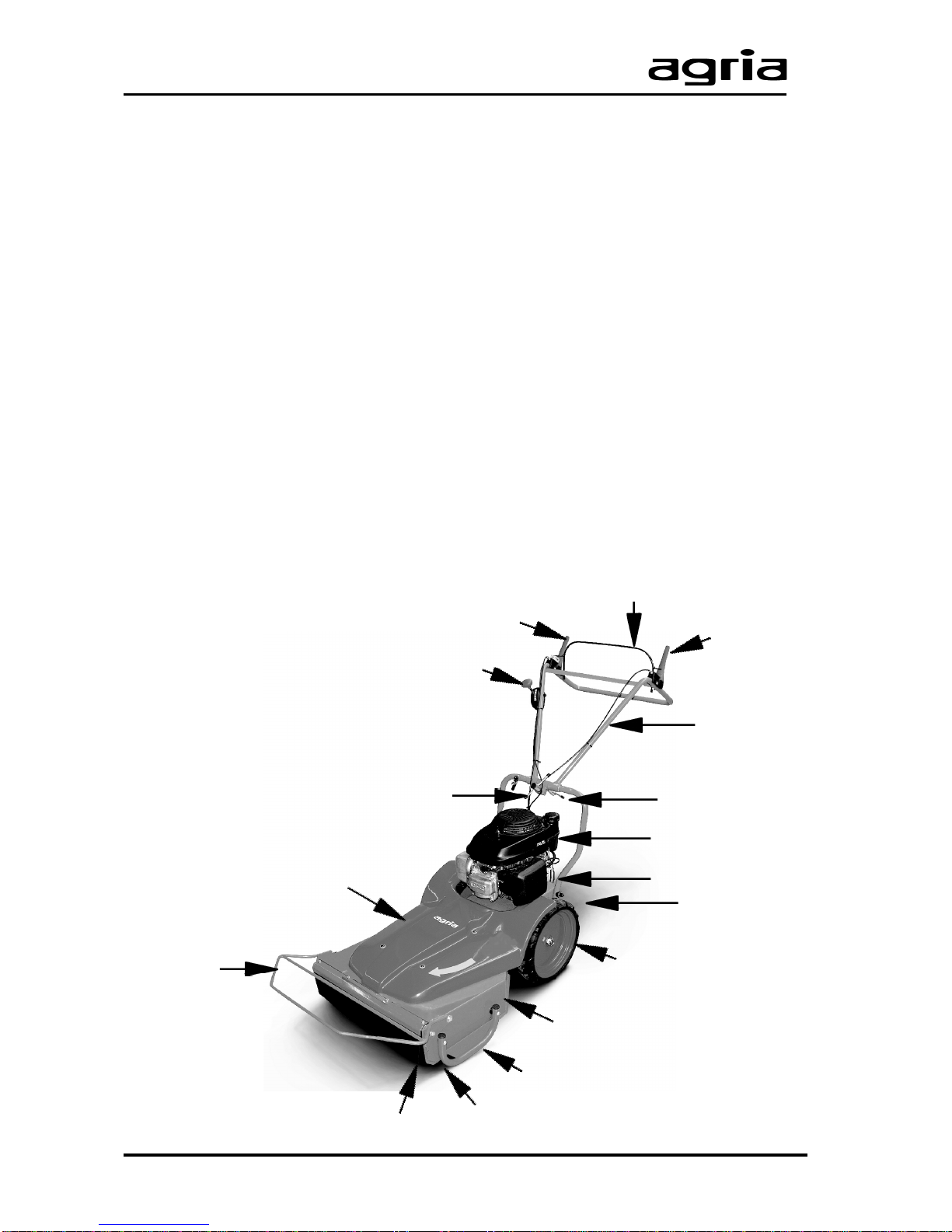
3
5
6
1
4
2
Amount of Delivery........................... 2
Symbols, Name Plate ....................... 2
Designation of Parts, Fig. A........... 3
Recommendations............................ 4
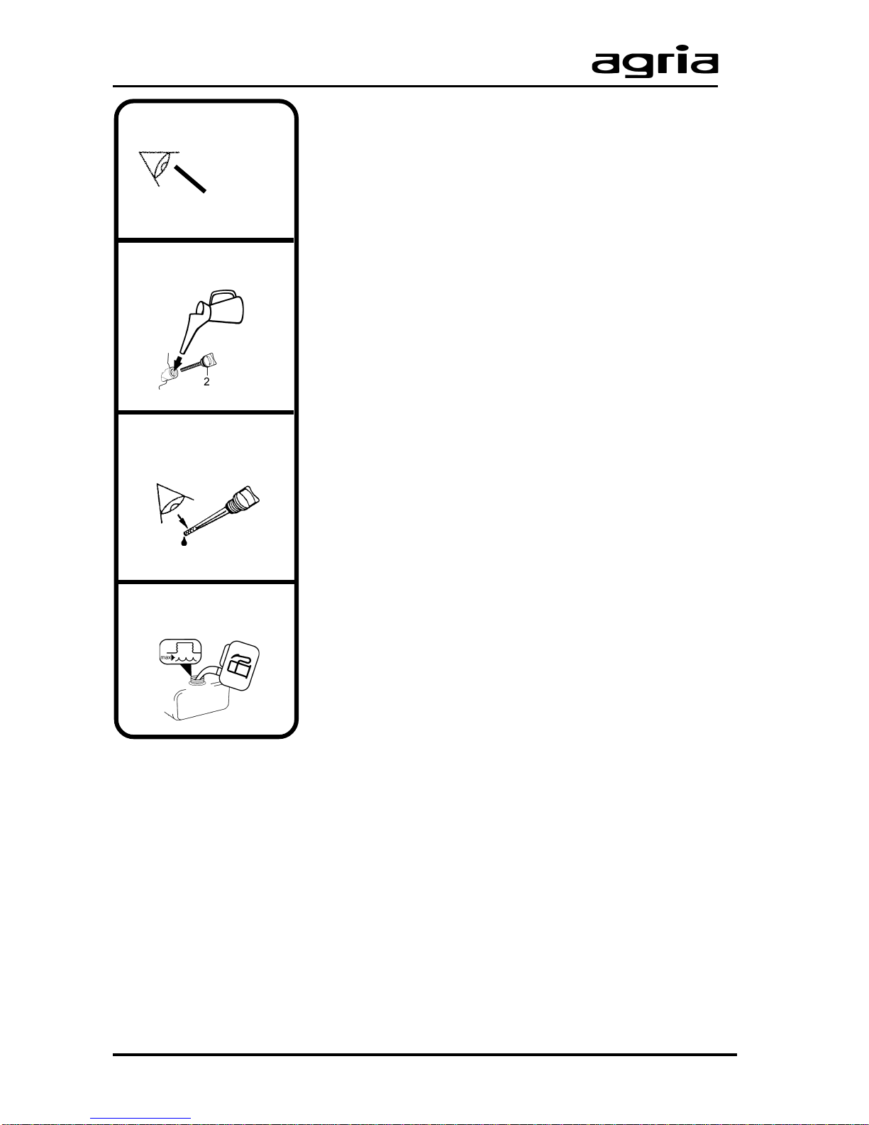
Instructions for Unpacking and Assembly .6
1. Safety Instructions ..................... 8
2. Specifications ........................... 13
2.1 Brush Cutter ............................. 13
3. Devices and Operating Elements ...
14
3.1 Engine....................................... 14
3.2 Speed Control Lever................. 15
3.3 Safety Circuit ............................ 15
3.4Travelling Drive.......................... 16
3.5 Mowing Drive............................ 16
3.6 Switching to mowing................. 16
3.7 Switching to travelling............... 16
3.8 ShiftingYoke............................. 16
3.9 Steering Handle ...............................
17
3.10 Transportation Position ...................
17
3.11 Cutting height.................................. 18
3.12
Slinging grip ..............................
18
4. Commissioning and Operation 19
4.1 Commissioning the Machine .... 19
4.2 Starting the Engine................... 20
4.3 Shutting off the Engine ............. 21
4.4 Driving....................................... 22
4.5 Stopping.................................... 22
4.6 Mowing ..................................... 23
4.7 Stopping.................................... 23
4.8 Danger Zone............................. 24
4.9 Mowing on Slopes .................... 25
4.10 Notes for Mowing/Mulching .... 26
5. Maintenance ............................ 27
5.1 Engine..................................... 27
5.2 Cleening the Cooling Screen.. 27
5.3 Cooling System ...................... 27
5.4 Exhaust................................... 27
5.5 Speed Actuating Devices ....... 27
5.6 Gearbox.................................. 28
5.7 Drive-Wheels .......................... 28
5.8 Bowden Cables....................... 28
5.9 Protection Liners..................... 28
5.10 Knife change......................... 29
5.11 Re-Grinding Mowing Knives .29
5.12 V-Belt Tension for Travelling
Drive.............................................. 30
5.13 Switch for Travelling Drive.... 30
5.14 Switch for Mowing Drive....... 30
5.15 Changing V-belt .................... 31
5.16 Cutter Brake.......................... 31
5.17 General Maintenance ........... 32
5.17 Cleaning................................ 32
5.18 Disposal ................................ 32
6.Troubleshooting ...................... 34
Varnishes, Wear Parts .................. 36
Inspection and
Maintenance Chart..................... 37
Designation of Parts, Fig. B ....... 38
Conformity Declaration .............. 39
Note fold-out pages!
Fig. A, Machine .............................. 3
Fig. B, Engine .............................. 38